reset RENAULT SCENIC 2010 J95 / 3.G Petrol Injection S3000 Injection Workshop Manual
[x] Cancel search | Manufacturer: RENAULT, Model Year: 2010, Model line: SCENIC, Model: RENAULT SCENIC 2010 J95 / 3.GPages: 230, PDF Size: 0.92 MB
Page 20 of 230

PETROL INJECTION
Fault finding - System operation
17B
17B - 20
PETROL INJECTION
Fault finding - System operation
17B
17B - 20V9 MR-372-J84-17B050$094.mif
S3000 Injection
Program No.: AD
Vdiag No.: 4C / 54
8. Mileage travelled with fault
These two parameters PR105 Distance travelled with OBD fault warning light on and PR106 Distance travelled
with fault warning light on are used to count the distance travelled with one of the injection fault warning lights lit:
level 1 fault warning light (amber) as well as the OBD warning light.
These counters can be reset to 0 using the diagnostic tool (clear faults command).
9. Inter-system engine functions
The inter-system connections concerning the particular requirements of engine management are as follows:
–OBD warning light illumination request by the instrument panel computer to prevent a pollution fault,
–level 1 warning light illumination request to warn of an operating safety fault relating to the injection system,
–level 2 warning light illumination request to warn of an operating safety fault or provide an engine
overheating alert,
– request for fan assembly activation for engine cooling, but also for the air conditioning and automatic
gearbox,
– air conditioning compressor shut-down request for engine programming requirements such as pulling away,
performance, anti-stalling, overspeed, etc.
– passenger compartment heating resistor shut-down or fixing request for engine programming requirements
such as pulling away, performance, anti-stall, overspeed, etc.
Page 26 of 230

PETROL INJECTION
Fault finding - Replacement of components
17B
17B-26
PETROL INJECTION
Fault finding - Replacement of components
17B
17B-26V9 MR-372-J84-17B050$188.mif
S3000 Injection
Program No.: AD
Vdiag No.: 4C / 54PETROL INJECTION
Fault finding - Replacement of components
1. COMPUTER REPLACEMENT OR REPROGRAMMING OPERATIONS
The system can be programmed and reprogrammed via the diagnostic socket using the RENAULT CLIP diagnostic
tool (Consult Technical Note 3585A or follow the instructions provided by the diagnostic tool).
Whenever the computer has been programmed, reprogrammed or replaced:
–Switch off the ignition.
–Start and then stop the engine (to initialise the computer) and wait 30 seconds.
–Switch the ignition back on and use the diagnostic tool to carry out the following steps:
– use command VP020 Enter VIN.
– deal with any faults declared by the diagnostic tool. Clear the computer memory.
– program the flywheel sensor target and throttle stops,
– carry out a road test followed by another check with the diagnostic tool. IMPORTANT
–Switch on the diagnostic tool (mains or cigarette lighter supply).
–Connect a battery charger (during the entire computer (re)programming procedure, the engine fan
assemblies are triggered automatically).
–Observe the engine temperature setpoints given on the diagnostic tool before (re)programming.
–Cut off all the electrical consumers (interior lighting, air conditioning, radio, etc.).
Operations to be carried out before the injection computer is reprogrammed:
Before reprogramming the injection computer, move the main Cruise control/Speed limiter switch to the rest
position. The information about the cruise control or the speed limiter displayed on the instrument panel
disappears.
Otherwise, if the main switch remains in the cruise control or speed limiter position during and after reprogramming,
the Cruise control/Speed limiter function will not be operational.
The procedure for resetting the function is as follows:
Vehicle ignition on.
– Position the main switch in rest position (the computer then detects the rest position).
– Position the switch in Cruise control position to activate the Cruise control function.
– Position the switch in Speed limiter position to activate the Speed limiter function.
IMPORTANT
It is not possible to try an injection computer coming from the Parts Department because it will no longer be
possible to use it on another vehicle.
MR-372-J84-17B050$188.mif
Page 179 of 230

PETROL INJECTION
Fault finding - Interpretation of statuses
17B
17B - 179
PETROL INJECTION
Fault finding - Interpretation of statuses
17B
17B - 179V9 MR-372-J84-17B050$611.mif
S3000 Injection
Program No.: AD
Vdiag No.: 4C / 54
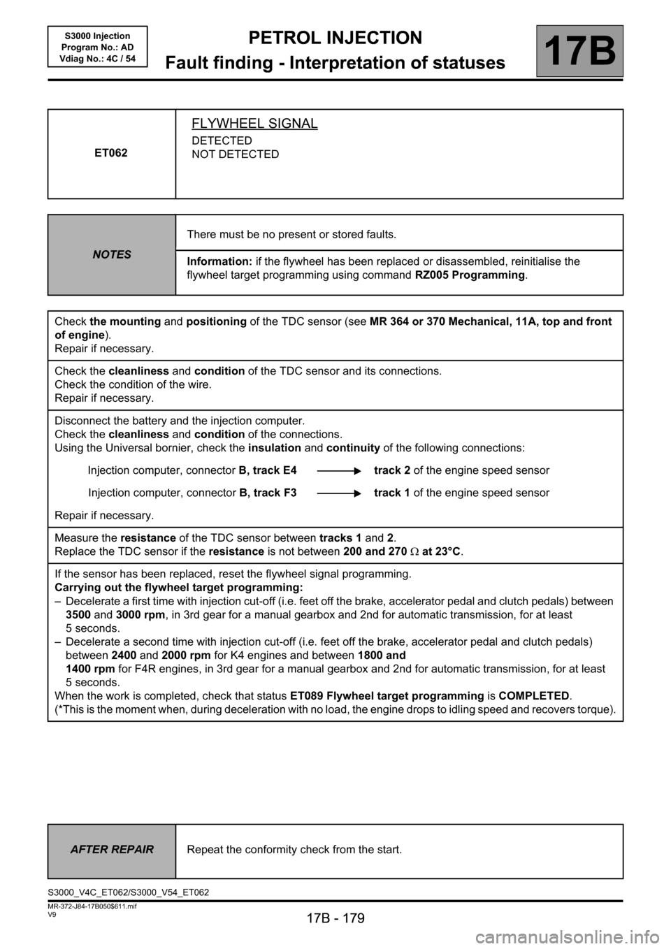
ET062
FLYWHEEL SIGNAL
DETECTED
NOT DETECTED
NOTESThere must be no present or stored faults.
Information: if the flywheel has been replaced or disassembled, reinitialise the
flywheel target programming using command RZ005 Programming.
Check the mounting and positioning of the TDC sensor (see MR 364 or 370 Mechanical, 11A, top and front
of engine).
Repair if necessary.
Check the cleanliness and condition of the TDC sensor and its connections.
Check the condition of the wire.
Repair if necessary.
Disconnect the battery and the injection computer.
Check the cleanliness and condition of the connections.
Using the Universal bornier, check the insulation and continuity of the following connections:
Injection computer, connectorB, track E4 track 2 of the engine speed sensor
Injection computer, connectorB, track F3 track 1 of the engine speed sensor
Repair if necessary.
Measure the resistance of the TDC sensor between tracks 1 and 2.
Replace the TDC sensor if the resistance is not between 200 and 270Ω at 23°C.
If the sensor has been replaced, reset the flywheel signal programming.
Carrying out the flywheel target programming:
– Decelerate a first time with injection cut-off (i.e. feet off the brake, accelerator pedal and clutch pedals) between
3500 and 3000 rpm, in 3rd gear for a manual gearbox and 2nd for automatic transmission, for at least
5 seconds.
– Decelerate a second time with injection cut-off (i.e. feet off the brake, accelerator pedal and clutch pedals)
between 2400 and 2000 rpm for K4 engines and between 1800 and
1400 rpm for F4R engines, in 3rd gear for a manual gearbox and 2nd for automatic transmission, for at least
5 seconds.
When the work is completed, check that status ET089 Flywheel target programming is COMPLETED.
(*This is the moment when, during deceleration with no load, the engine drops to idling speed and recovers torque).
AFTER REPAIRRepeat the conformity check from the start.
S3000_V4C_ET062/S3000_V54_ET062
Page 186 of 230

PETROL INJECTION
Fault finding - Interpretation of statuses
17B
17B - 186
PETROL INJECTION
Fault finding - Interpretation of statuses
17B
17B - 186V9 MR-372-J84-17B050$611.mif
S3000 Injection
Program No.: AD
Vdiag No.: 4C / 54
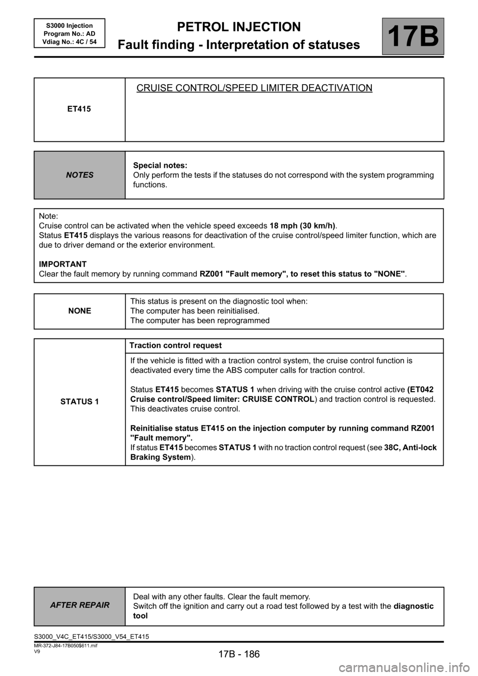
ET415
CRUISE CONTROL/SPEED LIMITER DEACTIVATION
NOTESSpecial notes:
Only perform the tests if the statuses do not correspond with the system programming
functions.
Note:
Cruise control can be activated when the vehicle speed exceeds 18 mph (30 km/h).
Status ET415 displays the various reasons for deactivation of the cruise control/speed limiter function, which are
due to driver demand or the exterior environment.
IMPORTANT
Clear the fault memory by running command RZ001 "Fault memory", to reset this status to "NONE".
NONEThis status is present on the diagnostic tool when:
The computer has been reinitialised.
The computer has been reprogrammed
STATUS 1Traction control request
If the vehicle is fitted with a traction control system, the cruise control function is
deactivated every time the ABS computer calls for traction control.
Status ET415 becomes STATUS 1 when driving with the cruise control active (ET042
Cruise control/Speed limiter: CRUISE CONTROL) and traction control is requested.
This deactivates cruise control.
Reinitialise status ET415 on the injection computer by running command RZ001
"Fault memory".
If status ET415 becomes STATUS 1 with no traction control request (see 38C, Anti-lock
Braking System).
AFTER REPAIRDeal with any other faults. Clear the fault memory.
Switch off the ignition and carry out a road test followed by a test with the diagnostic
tool
S3000_V4C_ET415/S3000_V54_ET415