stop start RENAULT SCENIC 2010 J95 / 3.G Petrol Injection S3000 Injection Workshop Manual
[x] Cancel search | Manufacturer: RENAULT, Model Year: 2010, Model line: SCENIC, Model: RENAULT SCENIC 2010 J95 / 3.GPages: 230, PDF Size: 0.92 MB
Page 13 of 230

PETROL INJECTION
Fault finding - System operation
17B
17B - 13
PETROL INJECTION
Fault finding - System operation
17B
17B - 13V9 MR-372-J84-17B050$094.mif
S3000 Injection
Program No.: AD
Vdiag No.: 4C / 54
In addition to turbocharging pressure management, the computer controls the engine for full load constant torque
operation.
This means that, irrespective of the engine conditions (air temperature, atmospheric pressure etc.), the maximum
torque will always be 275 Nm and the power 125 kW. So, for an air temperature of 20°C, the turbocharging pressure
at full load will be less than at 50°C. Despite controlled torque management, the turbocharging pressure can never
exceed 1800 mbar.
Ignition management
The advance is calculated for each cylinder. This may have a negative value, and is limited to between - 23.625°
and + 72° and includes any corrections due to pinking.
The slow loop anti-pinking correction is the maximum advance value that is deducted from the advance of one of the
cylinders. If none of the cylinders is pinking, this correction is zero.
Injectors
The injectors are controlled according to several modes. In particular, the engine is started in semi-full group mode
(injectors 1 and 4, then injectors 2 and 3 simultaneously), then it enters sequential mode, to ensure a correct start
whether or not it is correctly phased.
In fact in rare cases it is possible for the engine to run incorrectly phased if the Memo phasing program failed during
the last engine stop. So, since the system did not enter sequential injection mode and the cylinder 1 detection
program did not run, the injections are offset by 2 cylinders: therefore injecting in the order 4-2-1-3 rather than the
expected 1-3-4-2.
The injection time is constantly calculated and may be zero, in the event of cut-off during deceleration or overspeed
for example.
Page 19 of 230

PETROL INJECTION
Fault finding - System operation
17B
17B - 19
PETROL INJECTION
Fault finding - System operation
17B
17B - 19V9 MR-372-J84-17B050$094.mif
S3000 Injection
Program No.: AD
Vdiag No.: 4C / 54
Camshaft dephaser:
The camshaft dephaser ET083 Camshaft dephaser in defect mode may assume two different statuses.
●Status 1
This defect mode covers all faults that affect the dephaser position measurement. The dephaser is set to the
minimum stop and the camshaft angle measurement is forced to 0.
Tooth signal fault.
Tooth/camshaft signal consistency diagnostic.
●Status 2
This defect mode covers all faults affecting the dephaser (pulley and solenoid valve). The dephaser is set to
the minimum stop.
Electrical fault finding on the solenoid valve.
Dephaser position fault finding procedure.
7. Operational safety
Warning lights illumination
The S3000 Injection system manages the illumination of three warning lights and the display of warning messages
according to the severity of the faults detected, with the aim of informing the customer and guiding fault finding.
The injection computer manages the illumination of warning lights and warning messages displayed on the instrument
panel. These warning lights illuminate during the starting phase and in the event of an injection fault or engine
overheating.
The warning light illumination signals reach the instrument panel via the multiplex network.
Warning light illumination principle
During the starting phase (START button pressed) the OBD (On Board Diagnostic) warning light comes on for
approximately 3 seconds then goes out.
If there is an injection fault (level 1), the message CHECK INJECTION is lit, followed by the SERVICE warning light.
It indicates a reduced level of operation and a limited safety level.
The driver should carry out repairs as soon as possible.
Components involved:
– motorised throttle valve,
– accelerator pedal potentiometer,
– inlet manifold pressure sensor,
– computer,
– actuator feed,
– computer feed.
If there is a serious injection fault (level 2), the red engine symbol and the word STOP (display with information
display only), appears with the message ENGINE OVERHEATING followed by the STOP warning light and a
buzzer. If this happens, the vehicle must be stopped immediately.
When a fault causing excessive pollution in the exhaust gases is detected, the orange OBD warning light engine
symbol is lit:
–flashing in the event of a fault which might cause destruction of the catalytic converter (destructive misfires). If this
happens, the vehicle must be stopped immediately.
–constantly in the case of non-compliance with the anti-pollution standards (polluting misfires, catalytic converter
fault, oxygen sensor faults, inconsistency between the oxygen sensors and canister fault).
Page 26 of 230

PETROL INJECTION
Fault finding - Replacement of components
17B
17B-26
PETROL INJECTION
Fault finding - Replacement of components
17B
17B-26V9 MR-372-J84-17B050$188.mif
S3000 Injection
Program No.: AD
Vdiag No.: 4C / 54PETROL INJECTION
Fault finding - Replacement of components
1. COMPUTER REPLACEMENT OR REPROGRAMMING OPERATIONS
The system can be programmed and reprogrammed via the diagnostic socket using the RENAULT CLIP diagnostic
tool (Consult Technical Note 3585A or follow the instructions provided by the diagnostic tool).
Whenever the computer has been programmed, reprogrammed or replaced:
–Switch off the ignition.
–Start and then stop the engine (to initialise the computer) and wait 30 seconds.
–Switch the ignition back on and use the diagnostic tool to carry out the following steps:
– use command VP020 Enter VIN.
– deal with any faults declared by the diagnostic tool. Clear the computer memory.
– program the flywheel sensor target and throttle stops,
– carry out a road test followed by another check with the diagnostic tool. IMPORTANT
–Switch on the diagnostic tool (mains or cigarette lighter supply).
–Connect a battery charger (during the entire computer (re)programming procedure, the engine fan
assemblies are triggered automatically).
–Observe the engine temperature setpoints given on the diagnostic tool before (re)programming.
–Cut off all the electrical consumers (interior lighting, air conditioning, radio, etc.).
Operations to be carried out before the injection computer is reprogrammed:
Before reprogramming the injection computer, move the main Cruise control/Speed limiter switch to the rest
position. The information about the cruise control or the speed limiter displayed on the instrument panel
disappears.
Otherwise, if the main switch remains in the cruise control or speed limiter position during and after reprogramming,
the Cruise control/Speed limiter function will not be operational.
The procedure for resetting the function is as follows:
Vehicle ignition on.
– Position the main switch in rest position (the computer then detects the rest position).
– Position the switch in Cruise control position to activate the Cruise control function.
– Position the switch in Speed limiter position to activate the Speed limiter function.
IMPORTANT
It is not possible to try an injection computer coming from the Parts Department because it will no longer be
possible to use it on another vehicle.
MR-372-J84-17B050$188.mif
Page 53 of 230
PETROL INJECTION
Fault finding - Interpretation of faults
17B
17B-53
PETROL INJECTION
Fault finding - Interpretation of faults
17B
17B-53V9 MR-372-J84-17B050$329.mif
S3000 Injection
Program No.: AD
Vdiag No.: 4C / 54
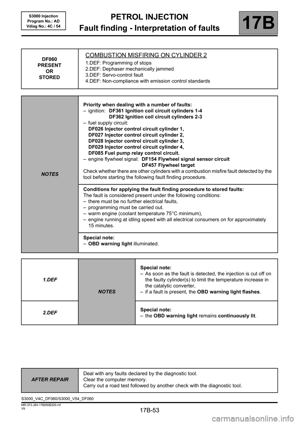
DF060
PRESENT
OR
STOREDCOMBUSTION MISFIRING ON CYLINDER 2
1.DEF: Programming of stops
2.DEF: Dephaser mechanically jammed
3.DEF: Servo-control fault
4.DEF: Non-compliance with emission control standards
NOTESPriority when dealing with a number of faults:
– ignition: DF361 Ignition coil circuit cylinders 1-4
DF362 Ignition coil circuit cylinders 2-3
– fuel supply circuit:
DF026 Injector control circuit cylinder 1,
DF027 Injector control circuit cylinder 2,
DF028 Injector control circuit cylinder 3,
DF029 Injector control circuit cylinder 4,
DF085 Fuel pump relay control circuit.
– engine flywheel signal: DF154 Flywheel signal sensor circuit
DF457 Flywheel target
Check whether there are other cylinders with a combustion misfire fault detected by the
tool before starting the following fault finding procedure.
Conditions for applying the fault finding procedure to stored faults:
The fault is considered present under the following conditions:
– there must be no further electrical faults,
– programming must be carried out.
– warm engine (coolant temperature 75°C minimum),
– engine running at idling speed with all electrical consumers on for approximately
15 minutes.
Special note:
–OBD warning light illuminated.
1.DEF
NOTESSpecial note:
– As soon as the fault is detected, the injection is cut off on
the faulty cylinder(s) to limit the temperature increase in
the catalytic converter,
– if a fault is present, the OBD warning light flashes.
2.DEFSpecial note:
–the OBD warning light remains continuously lit.
AFTER REPAIRDeal with any faults declared by the diagnostic tool.
Clear the computer memory.
Carry out a road test followed by another check with the diagnostic tool.
S3000_V4C_DF060/S3000_V54_DF060
Page 142 of 230
PETROL INJECTION
Fault finding - Conformity check
17B
17B-142
PETROL INJECTION
Fault finding - Conformity check
17B
17B-142V9 MR-372-J84-17B050$470.mif
S3000 Injection
Program No.: AD
Vdiag No.: 4C / 54
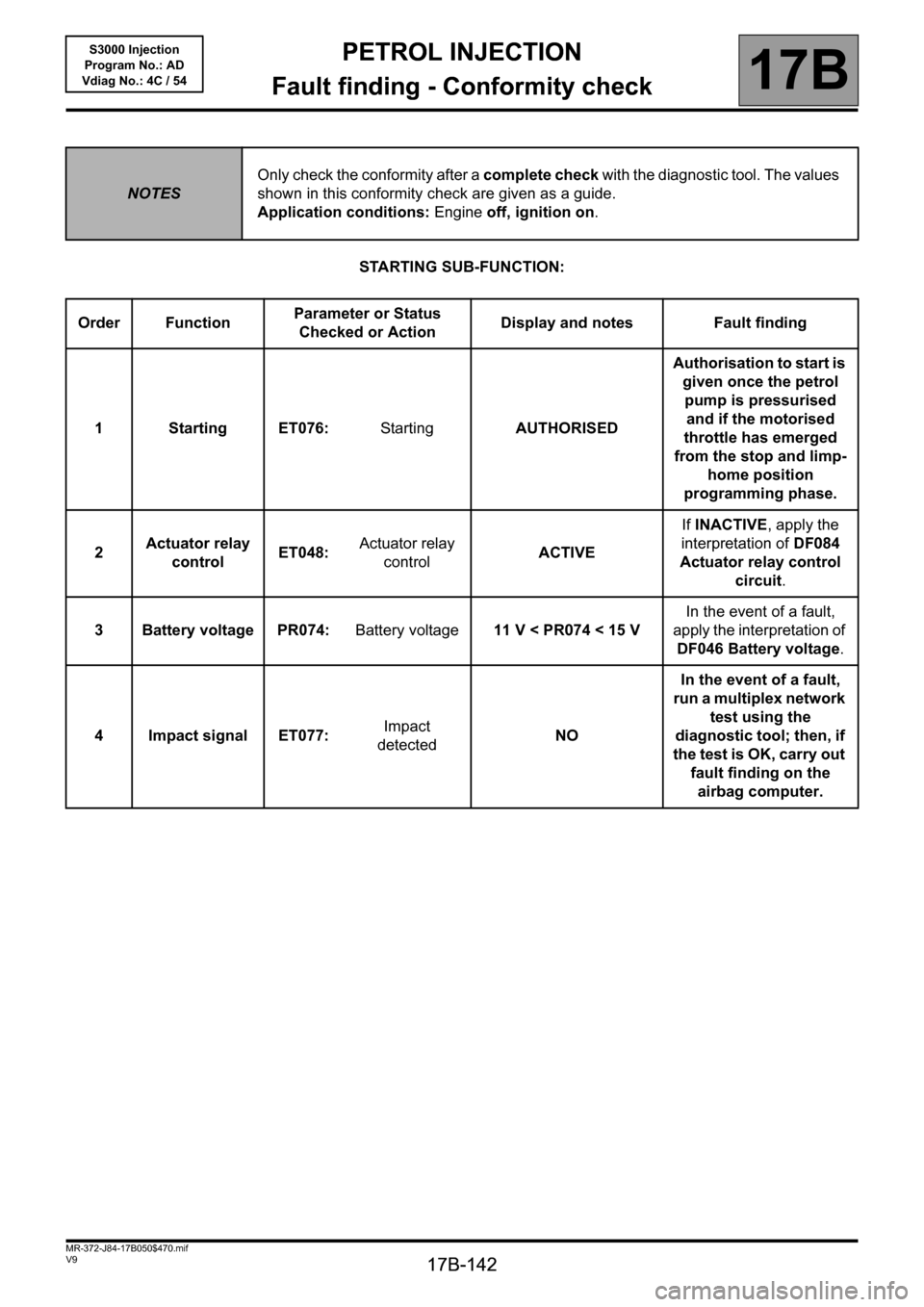
STARTING SUB-FUNCTION:
NOTESOnly check the conformity after a complete check with the diagnostic tool. The values
shown in this conformity check are given as a guide.
Application conditions: Engine off, ignition on.
Order FunctionParameter or Status
Checked or ActionDisplay and notes Fault finding
1StartingET076:StartingAUTHORISEDAuthorisation to start is
given once the petrol
pump is pressurised
and if the motorised
throttle has emerged
from the stop and limp-
home position
programming phase.
2Actuator relay
controlET048:Actuator relay
controlACTIVEIf INACTIVE, apply the
interpretation of DF084
Actuator relay control
circuit.
3 Battery voltage PR074:Battery voltage11 V < PR074 < 15 VIn the event of a fault,
apply the interpretation of
DF046 Battery voltage.
4 Impact signal ET077:Impact
detectedNOIn the event of a fault,
run a multiplex network
test using the
diagnostic tool; then, if
the test is OK, carry out
fault finding on the
airbag computer.
Page 143 of 230
PETROL INJECTION
Fault finding - Conformity check
17B
17B-143
PETROL INJECTION
Fault finding - Conformity check
17B
17B-143V9 MR-372-J84-17B050$470.mif
S3000 Injection
Program No.: AD
Vdiag No.: 4C / 54
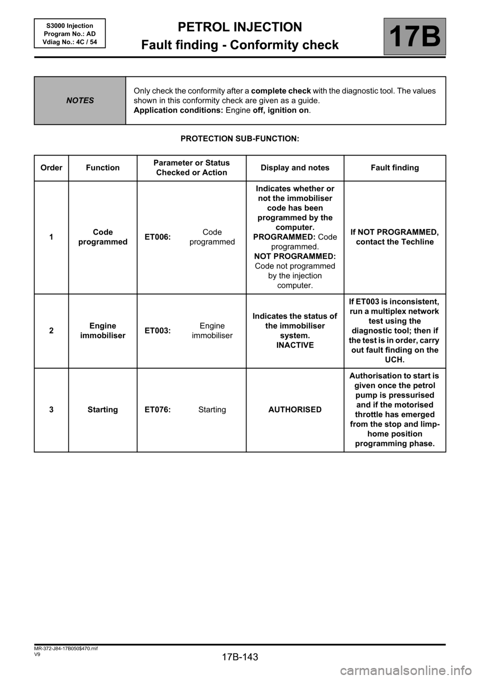
PROTECTION SUB-FUNCTION:
NOTESOnly check the conformity after a complete check with the diagnostic tool. The values
shown in this conformity check are given as a guide.
Application conditions: Engine off, ignition on.
Order FunctionParameter or Status
Checked or ActionDisplay and notes Fault finding
1Code
programmedET006:Code
programmedIndicates whether or
not the immobiliser
code has been
programmed by the
computer.
PROGRAMMED: Code
programmed.
NOT PROGRAMMED:
Code not programmed
by the injection
computer.If NOT PROGRAMMED,
contact the Techline
2Engine
immobiliserET003:Engine
immobiliserIndicates the status of
the immobiliser
system.
INACTIVEIf ET003 is inconsistent,
run a multiplex network
test using the
diagnostic tool; then if
the test is in order, carry
out fault finding on the
UCH.
3StartingET076:StartingAUTHORISEDAuthorisation to start is
given once the petrol
pump is pressurised
and if the motorised
throttle has emerged
from the stop and limp-
home position
programming phase.
Page 166 of 230
PETROL INJECTION
Fault finding - Conformity check
17B
17B-166
PETROL INJECTION
Fault finding - Conformity check
17B
17B-166V9 MR-372-J84-17B050$517.mif
S3000 Injection
Program No.: AD
Vdiag No.: 4C / 54
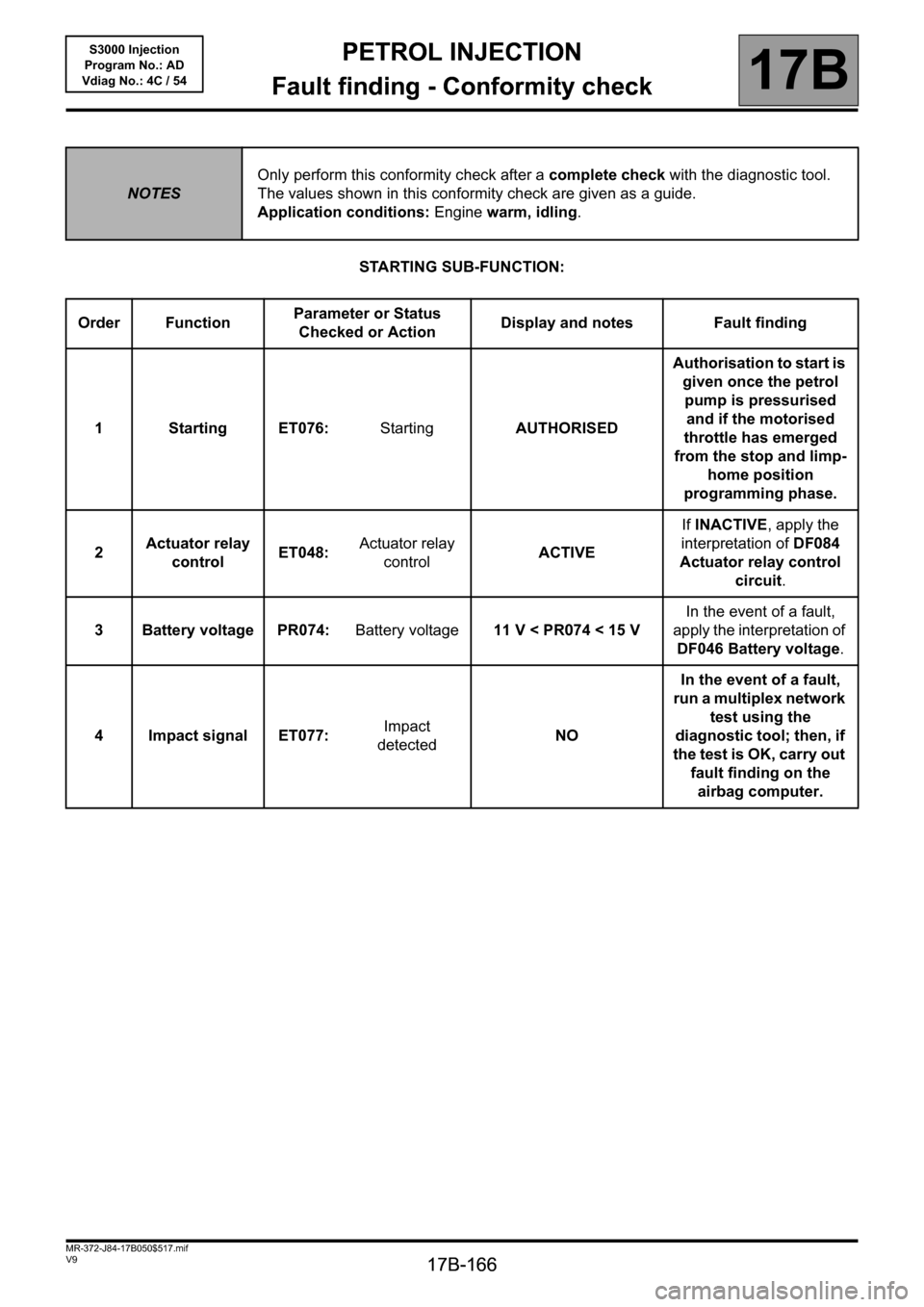
STARTING SUB-FUNCTION:
NOTESOnly perform this conformity check after a complete check with the diagnostic tool.
The values shown in this conformity check are given as a guide.
Application conditions: Engine warm, idling.
Order FunctionParameter or Status
Checked or ActionDisplay and notes Fault finding
1StartingET076:StartingAUTHORISEDAuthorisation to start is
given once the petrol
pump is pressurised
and if the motorised
throttle has emerged
from the stop and limp-
home position
programming phase.
2Actuator relay
controlET048:Actuator relay
controlACTIVEIf INACTIVE, apply the
interpretation of DF084
Actuator relay control
circuit.
3 Battery voltage PR074:Battery voltage11 V < PR074 < 15 VIn the event of a fault,
apply the interpretation of
DF046 Battery voltage.
4 Impact signal ET077:Impact
detectedNOIn the event of a fault,
run a multiplex network
test using the
diagnostic tool; then, if
the test is OK, carry out
fault finding on the
airbag computer.
Page 167 of 230
PETROL INJECTION
Fault finding - Conformity check
17B
17B-167
PETROL INJECTION
Fault finding - Conformity check
17B
17B-167V9 MR-372-J84-17B050$517.mif
S3000 Injection
Program No.: AD
Vdiag No.: 4C / 54
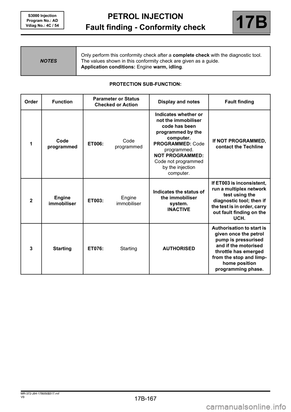
PROTECTION SUB-FUNCTION:
NOTESOnly perform this conformity check after a complete check with the diagnostic tool.
The values shown in this conformity check are given as a guide.
Application conditions: Engine warm, idling.
Order FunctionParameter or Status
Checked or ActionDisplay and notes Fault finding
1Code
programmedET006:Code
programmedIndicates whether or
not the immobiliser
code has been
programmed by the
computer.
PROGRAMMED: Code
programmed.
NOT PROGRAMMED:
Code not programmed
by the injection
computer.If NOT PROGRAMMED,
contact the Techline
2Engine
immobiliserET003:Engine
immobiliserIndicates the status of
the immobiliser
system.
INACTIVEIf ET003 is inconsistent,
run a multiplex network
test using the
diagnostic tool; then if
the test is in order, carry
out fault finding on the
UCH.
3StartingET076:StartingAUTHORISEDAuthorisation to start is
given once the petrol
pump is pressurised
and if the motorised
throttle has emerged
from the stop and limp-
home position
programming phase.
Page 180 of 230
PETROL INJECTION
Fault finding - Interpretation of statuses
17B
17B - 180
PETROL INJECTION
Fault finding - Interpretation of statuses
17B
17B - 180V9 MR-372-J84-17B050$611.mif
S3000 Injection
Program No.: AD
Vdiag No.: 4C / 54
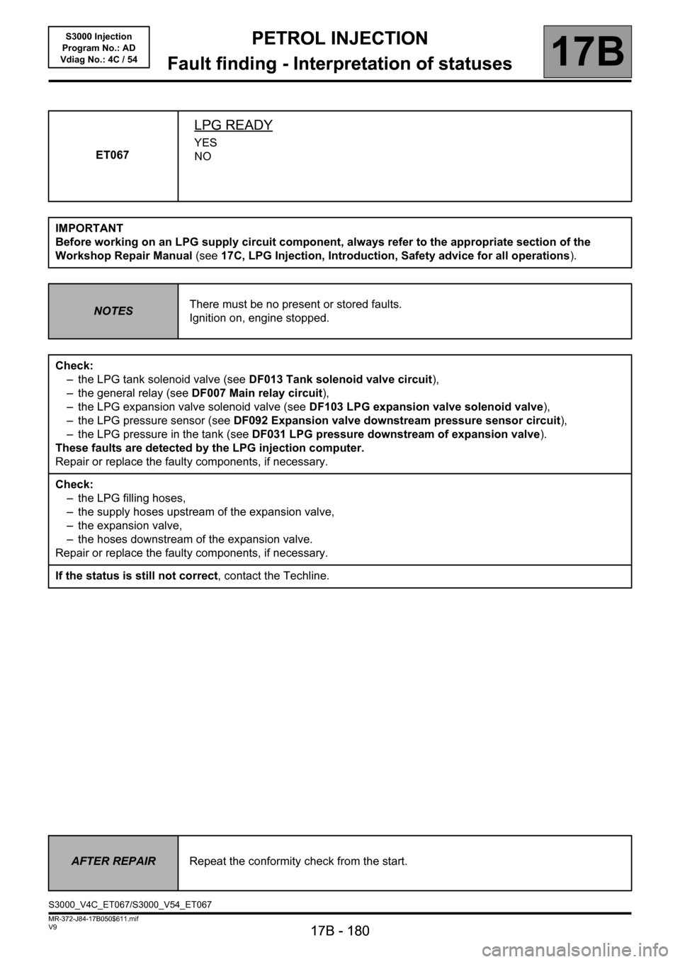
ET067
LPG READY
YES
NO
IMPORTANT
Before working on an LPG supply circuit component, always refer to the appropriate section of the
Workshop Repair Manual (see17C, LPG Injection, Introduction, Safety advice for all operations).
NOTESThere must be no present or stored faults.
Ignition on, engine stopped.
Check:
– the LPG tank solenoid valve (see DF013 Tank solenoid valve circuit),
– the general relay (see DF007 Main relay circuit),
– the LPG expansion valve solenoid valve (see DF103 LPG expansion valve solenoid valve),
– the LPG pressure sensor (see DF092 Expansion valve downstream pressure sensor circuit),
– the LPG pressure in the tank (see DF031 LPG pressure downstream of expansion valve).
These faults are detected by the LPG injection computer.
Repair or replace the faulty components, if necessary.
Check:
– the LPG filling hoses,
– the supply hoses upstream of the expansion valve,
– the expansion valve,
– the hoses downstream of the expansion valve.
Repair or replace the faulty components, if necessary.
If the status is still not correct, contact the Techline.
AFTER REPAIRRepeat the conformity check from the start.
S3000_V4C_ET067/S3000_V54_ET067
Page 181 of 230
PETROL INJECTION
Fault finding - Interpretation of statuses
17B
17B - 181
PETROL INJECTION
Fault finding - Interpretation of statuses
17B
17B - 181V9 MR-372-J84-17B050$611.mif
S3000 Injection
Program No.: AD
Vdiag No.: 4C / 54
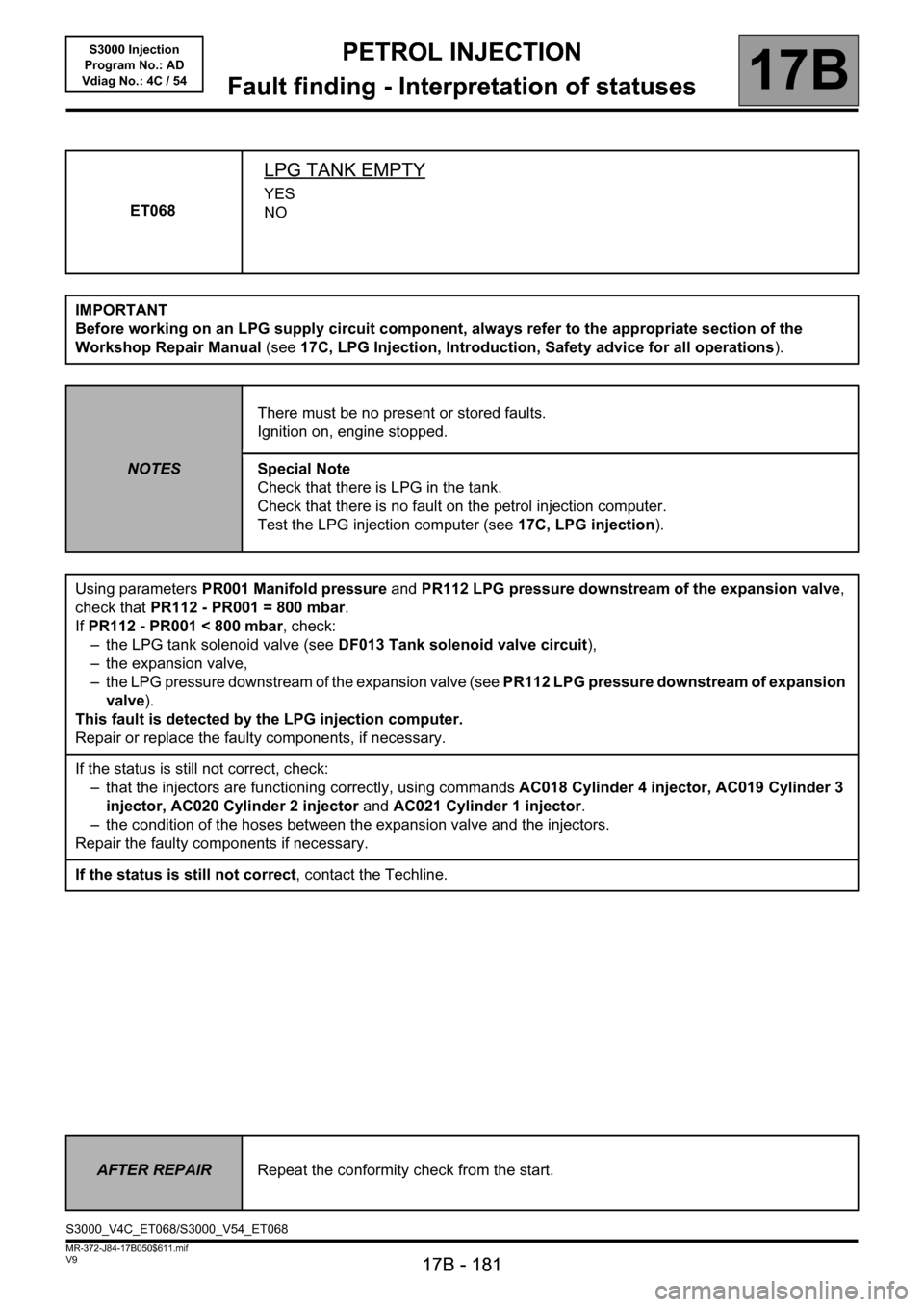
ET068
LPG TANK EMPTY
YES
NO
IMPORTANT
Before working on an LPG supply circuit component, always refer to the appropriate section of the
Workshop Repair Manual (see17C, LPG Injection, Introduction, Safety advice for all operations).
NOTESThere must be no present or stored faults.
Ignition on, engine stopped.
Special Note
Check that there is LPG in the tank.
Check that there is no fault on the petrol injection computer.
Test the LPG injection computer (see17C, LPG injection).
Using parameters PR001 Manifold pressure and PR112 LPG pressure downstream of the expansion valve,
check that PR112 - PR001 = 800 mbar.
If PR112 - PR001 < 800 mbar, check:
– the LPG tank solenoid valve (see DF013 Tank solenoid valve circuit),
– the expansion valve,
– the LPG pressure downstream of the expansion valve (see PR112 LPG pressure downstream of expansion
valve).
This fault is detected by the LPG injection computer.
Repair or replace the faulty components, if necessary.
If the status is still not correct, check:
– that the injectors are functioning correctly, using commands AC018 Cylinder 4 injector, AC019 Cylinder 3
injector, AC020 Cylinder 2 injector and AC021 Cylinder 1 injector.
– the condition of the hoses between the expansion valve and the injectors.
Repair the faulty components if necessary.
If the status is still not correct, contact the Techline.
AFTER REPAIRRepeat the conformity check from the start.
S3000_V4C_ET068/S3000_V54_ET068