torque RENAULT SCENIC 2010 J95 / 3.G Petrol Injection S3000 Injection Workshop Manual
[x] Cancel search | Manufacturer: RENAULT, Model Year: 2010, Model line: SCENIC, Model: RENAULT SCENIC 2010 J95 / 3.GPages: 230, PDF Size: 0.92 MB
Page 8 of 230

PETROL INJECTION
Fault finding - System operation
17B
17B - 8
PETROL INJECTION
Fault finding - System operation
17B
17B - 8V9 MR-372-J84-17B050$094.mif
S3000 Injection
Program No.: AD
Vdiag No.: 4C / 54
2. Role of components, operating strategy
Engine immobiliser
The Verlog 4 type immobiliser function is managed by the UCH computer and the engine management computer.
Before any starting request, the engine management computer is protected.
When a starting request is made, the injection computer and the UCH exchange authentication data via the multiplex
network; this determines whether the engine start is authorised.
After more than 5 consecutive failed authentication attempts, the engine management computer goes into protection
(antiscanning) mode and no longer tries to authenticate the UCH computer. It only exits this mode when the
following sequence of operations occurs:
– the ignition is left on for at least 20 seconds,
– the message is switched off,
– the injection computer self-supply cuts out when it should (the time varies according to engine temperature).
After this, only one authentication attempt is allowed. If this fails again, repeat the sequence of operations described
above.
If the engine management computer still fails to unlock, contact the Techline.
Impact detected
If an impact has been stored by the injection computer, switch off the ignition for 10 seconds, then switch it back on
so that the engine can be started. Clear the faults.
Torque management
The torque structure is the system for managing engine torque. It is necessary for some functions such as the
electronic stability program (ESP) and the automatic gearbox.
Each inter-system (ESP and automatic gearbox) sends a request for torque via the multiplex network to the injection
computer. It arbitrates between the inter-system torque requests and the driver's request (pedal or cruise control/
speed limiter). The result of the arbitration gives the torque setpoint. The torque structure uses the torque setpoint to
calculate the throttle position setpoint, the advance and, if there is turbocharging, the turbocharger valve setpoint
(wastegate) for engines fitted with a turbocharger. WARNING
Disconnect the injection computer when carrying out any welding work on the vehicle.
Page 9 of 230

PETROL INJECTION
Fault finding - System operation
17B
17B - 9
PETROL INJECTION
Fault finding - System operation
17B
17B - 9V9 MR-372-J84-17B050$094.mif
S3000 Injection
Program No.: AD
Vdiag No.: 4C / 54
Camshaft dephaser
Its role is to modify the valve timing.
The camshaft dephaser is continuously variable in operation.
In applications without a camshaft sensor, the engine phasing is controlled by software. This is the case on engines
that do not have a camshaft dephaser.
This information can be displayed by reading configuration LC008 Camshaft dephaser.
A first strategy called "Memo phasing" is applied to phase the engine management on starting according to the data
recorded when the engine last stalled. Wait for the end of auto-feed (power latch and therefore this data being
saved) before disconnecting the computer.
Then, a second program confirms the first decision. It is based on torque analysis.
The injection computer actuates a camshaft dephaser that varies according to the engine:
–K4M engine
Continuous variable inlet camshaft dephaser between 0 and 43° of the crankshaft, controlled by a solenoid
valve supplied by an opening cycle ratio circuit through the injection computer.
–F4R and F4R-T engines
Inlet camshaft dephaser controlled by a solenoid valve with an all or nothing supply from the injection
computer.
Camshaft position sensor (non-LPG K4M only)
The role of the camshaft sensor is:
– to locate the computer cylinders so that the computer correctly synchronises the sequential injection,
– checks the position of the inlet camshaft.
Motorised throttle valve
The throttle valve carries out idling speed regulation and engine air intake modulation functions. It comprises an
electric motor and two throttle position potentiometers.
When the engine is idling, the throttle position is regulated according to the idling speed setpoint. This setpoint takes
into account the major power consumers (air conditioning) and operating conditions (air temperature and coolant
temperature).
Page 13 of 230

PETROL INJECTION
Fault finding - System operation
17B
17B - 13
PETROL INJECTION
Fault finding - System operation
17B
17B - 13V9 MR-372-J84-17B050$094.mif
S3000 Injection
Program No.: AD
Vdiag No.: 4C / 54
In addition to turbocharging pressure management, the computer controls the engine for full load constant torque
operation.
This means that, irrespective of the engine conditions (air temperature, atmospheric pressure etc.), the maximum
torque will always be 275 Nm and the power 125 kW. So, for an air temperature of 20°C, the turbocharging pressure
at full load will be less than at 50°C. Despite controlled torque management, the turbocharging pressure can never
exceed 1800 mbar.
Ignition management
The advance is calculated for each cylinder. This may have a negative value, and is limited to between - 23.625°
and + 72° and includes any corrections due to pinking.
The slow loop anti-pinking correction is the maximum advance value that is deducted from the advance of one of the
cylinders. If none of the cylinders is pinking, this correction is zero.
Injectors
The injectors are controlled according to several modes. In particular, the engine is started in semi-full group mode
(injectors 1 and 4, then injectors 2 and 3 simultaneously), then it enters sequential mode, to ensure a correct start
whether or not it is correctly phased.
In fact in rare cases it is possible for the engine to run incorrectly phased if the Memo phasing program failed during
the last engine stop. So, since the system did not enter sequential injection mode and the cylinder 1 detection
program did not run, the injections are offset by 2 cylinders: therefore injecting in the order 4-2-1-3 rather than the
expected 1-3-4-2.
The injection time is constantly calculated and may be zero, in the event of cut-off during deceleration or overspeed
for example.
Page 16 of 230

PETROL INJECTION
Fault finding - System operation
17B
17B - 16
PETROL INJECTION
Fault finding - System operation
17B
17B - 16V9 MR-372-J84-17B050$094.mif
S3000 Injection
Program No.: AD
Vdiag No.: 4C / 54
4. Engine coolant temperature management
Engine cooling is provided by 1 or 2 fan assemblies (depending on the vehicle layout). The injection computer
requests the UPC to actuate them via the multiplex network.
To provide cooling:
Engine running, GMV1 is requested when the coolant temperature exceeds 99 °C and stops when the coolant
temperature falls below 96 °C. GMV2 is requested when the coolant temperature exceeds 102 °C and stops when
the coolant temperature falls below 99 °C.
With the engine off, only fan assembly 1 may be activated to provide the anti-percolation function (if engine is
stopped when very hot). The anti-percolation function is active with the ignition off for a determined period. During
this period, fan assembly 1 is requested if the coolant temperature exceeds approximately 100 °C and is shut down
if the coolant temperature drops below around 95 °C.
If a fault is detected on the coolant temperature sensor circuit, then fan assembly 1 is requested to operate
continuously.
If the engine coolant temperature goes beyond the warning threshold of 11 8 ° C, the injection computer requests the
instrument panel computer via the multiplex network to illuminate on the coolant temperature warning light until the
coolant temperature falls back below 115 ° C.
In addition to the engine requirements, the injection computer centralises the cooling requirements for the Air
conditioning and BVA/BVR functions.
5. Air conditioning function
The S3000 computer manages a cold loop air conditioning system.
– air conditioning request via multiplex connection,
– acquisition of air conditioning circuit pressure,
– vehicle speed
– air conditioning compressor control,
– fan assembly control request by Protection and Switching Unit.
The injection computer recovers the power absorbed by the air conditioning compressor and the fast idling speed
request using the pressure acquired in the air conditioning circuit.
These signals are necessary for adapting the engine management (idling speed regulation, air flow correction, etc.),
for several reasons:
– air conditioning compressor efficiency,
– sturdier engine to torque bucking caused by compressor activation,
– helping the alternator.
Requests for fan assembly 1 and/or fan assembly 2 are recovered based on the air conditioning circuit pressure and
the vehicle speed. In short, the lower the speed and the higher the pressure, the greater the fan assembly requests.
Page 17 of 230

PETROL INJECTION
Fault finding - System operation
17B
17B - 17
PETROL INJECTION
Fault finding - System operation
17B
17B - 17V9 MR-372-J84-17B050$094.mif
S3000 Injection
Program No.: AD
Vdiag No.: 4C / 54
6. Defect modes
Motorised throttle valve
In defect mode, the motorised throttle valve can have 6 different statuses.
Any entry into type 1 to 5 defect mode always leads to the application of type 6. Type 1The throttle opening is less than the Safe mode position. The throttle is no longer activated and is
automatically in Safe mode. The ESP, distance control and cruise control/speed limiter systems are
disabled. The automatic transmission is in "Safe mode".
Type 2The throttle opening is no longer actuated. The engine speed is limited by injection cut-off.
Type 3Defect mode is associated with restructuring of the pedal setpoints (constant pedal setpoint for each
gear).
Type 4The associated defect mode restricts the throttle opening. The maximum throttle valve opening
threshold results in a speed of below 54 mph (90 km/h).
Type 5The computer no longer processes torque changes requested by the ESP, distance control, cruise
control/speed limiter and automatic gearbox systems. This defect mode results from a computer
malfunction, or a fault with the manifold or turbocharging pressure sensor. The system then only uses
the accelerator pedal signal. The ESP, distance control and cruise control/speed limiter systems are
disabled. The automatic transmission is in "Safe mode".
Type 6The turbocharging valve no longer works.
Page 29 of 230

PETROL INJECTION
Fault finding - Configurations and programming17B
17B - 29
17B
17B - 29V9 MR-372-J84-17B050$235.mif
S3000 Injection
Program No.: AD
Vdiag No.: 4C / 54
2. PROGRAMMING
Programming the flywheel target
– Decelerate a first time with injection cut-off (i.e. feet off the brake, accelerator pedal and clutch pedals) between
3500 and 3000 rpm, in 3rd gear for a manual gearbox and 2nd for automatic transmission, for at least 5 seconds.
– Decelerate a second time with injection cut-off (i.e. feet off the brake, accelerator pedal and clutch pedals) between
2400 and 2000 rpm for K4 engines and between 1800 and 1400 rpm for R4R engines, in 3rd gear for a manual
gearbox and 2nd for automatic gearbox, for at least 5 seconds.
Check the programming using ET089 Flywheel target programming.
Programming the throttle end stops
When replacing the computer or the motorised throttle valve, with the ignition on, wait 30 seconds so that the
computer may program the MAX and MIN limits, then switch off the ignition and wait 30 seconds for the end of the
Power Latch, so that the computer may store the programmed limits.
Check the programming using ET051 Throttle stop programming.
* This is the moment when, during deceleration with no load, the engine drops to idling speed and recovers torque. LC158Air conditioning heating resistor management
→WITH
→NONE
LC162Controlled coolant thermostat
→WITH
→NONE
LC170Electric coolant pump
→WITH
→NONE
Page 88 of 230

PETROL INJECTION
Fault finding - Interpretation of faults
17B
17B-88
PETROL INJECTION
Fault finding - Interpretation of faults
17B
17B-88V9 MR-372-J84-17B050$376.mif
S3000 Injection
Program No.: AD
Vdiag No.: 4C / 54
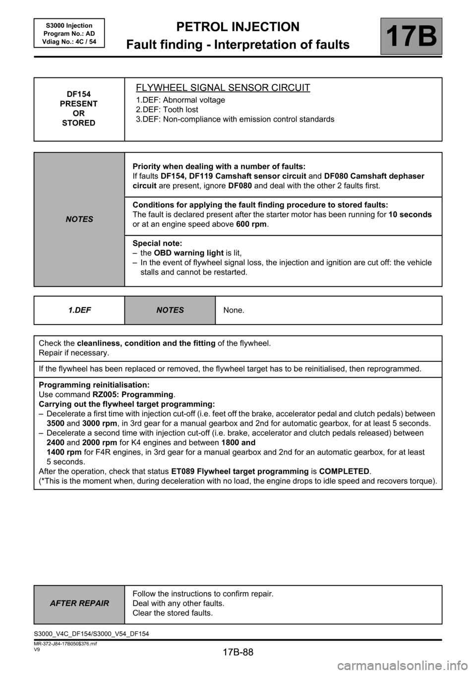
DF154
PRESENT
OR
STOREDFLYWHEEL SIGNAL SENSOR CIRCUIT
1.DEF: Abnormal voltage
2.DEF: Tooth lost
3.DEF: Non-compliance with emission control standards
NOTESPriority when dealing with a number of faults:
If faults DF154, DF119 Camshaft sensor circuit and DF080 Camshaft dephaser
circuit are present, ignore DF080 and deal with the other 2 faults first.
Conditions for applying the fault finding procedure to stored faults:
The fault is declared present after the starter motor has been running for 10 seconds
or at an engine speed above 600 rpm.
Special note:
–the OBD warning light is lit,
– In the event of flywheel signal loss, the injection and ignition are cut off: the vehicle
stalls and cannot be restarted.
1.DEF
NOTESNone.
Check the cleanliness, condition and the fitting of the flywheel.
Repair if necessary.
If the flywheel has been replaced or removed, the flywheel target has to be reinitialised, then reprogrammed.
Programming reinitialisation:
Use command RZ005: Programming.
Carrying out the flywheel target programming:
– Decelerate a first time with injection cut-off (i.e. feet off the brake, accelerator pedal and clutch pedals) between
3500 and 3000 rpm, in 3rd gear for a manual gearbox and 2nd for automatic gearbox, for at least 5 seconds.
– Decelerate a second time with injection cut-off (i.e. brake, accelerator and clutch pedals released) between
2400and 2000 rpm for K4 engines and between 1800 and
1400 rpm for F4R engines, in 3rd gear for a manual gearbox and 2nd for an automatic gearbox, for at least
5 seconds.
After the operation, check that status ET089 Flywheel target programming is COMPLETED.
(*This is the moment when, during deceleration with no load, the engine drops to idle speed and recovers torque).
AFTER REPAIRFollow the instructions to confirm repair.
Deal with any other faults.
Clear the stored faults.
S3000_V4C_DF154/S3000_V54_DF154
Page 89 of 230

PETROL INJECTION
Fault finding - Interpretation of faults
17B
17B-89
PETROL INJECTION
Fault finding - Interpretation of faults
17B
17B-89V9 MR-372-J84-17B050$376.mif
S3000 Injection
Program No.: AD
Vdiag No.: 4C / 54
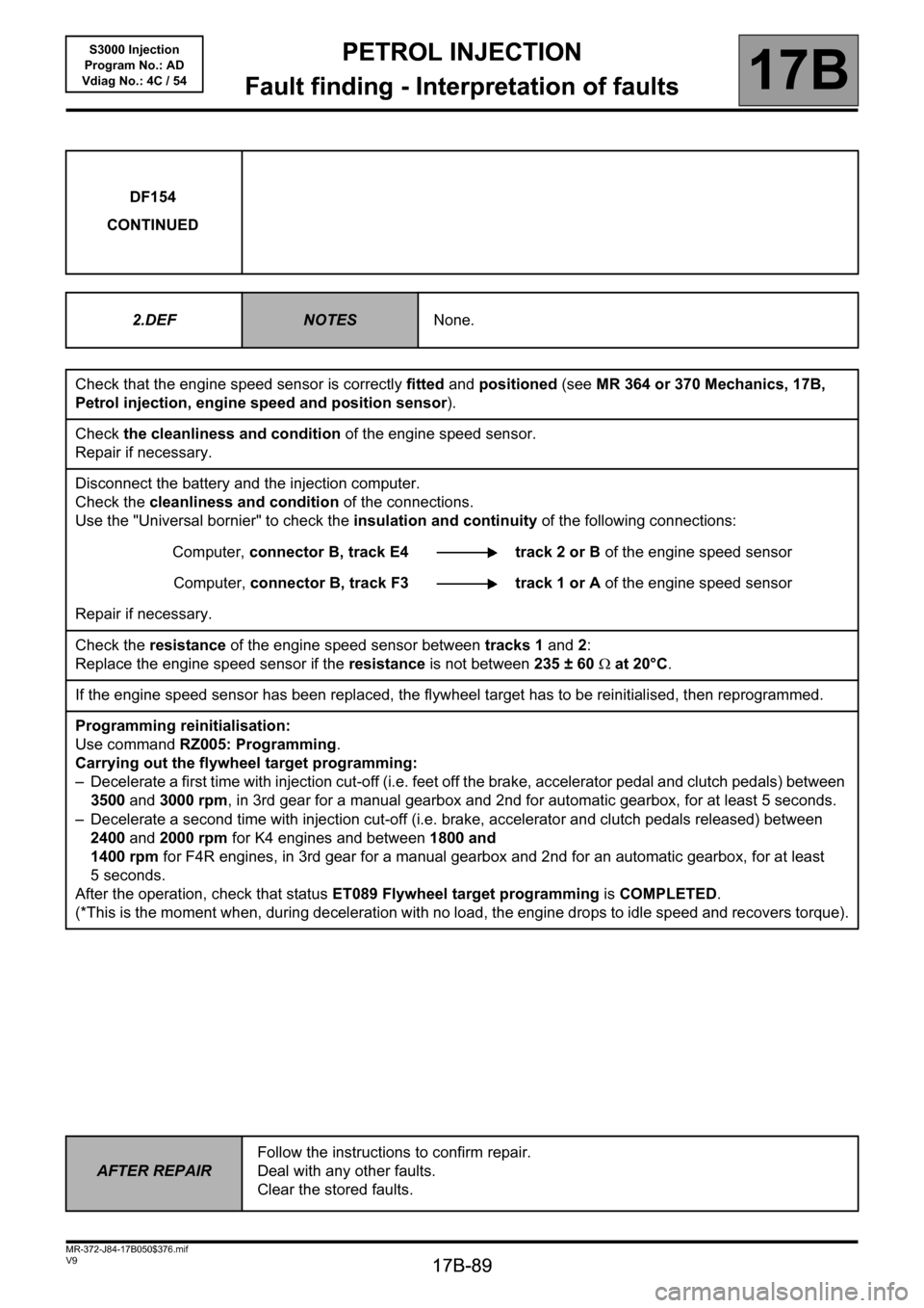
DF154
CONTINUED
2.DEF
NOTESNone.
Check that the engine speed sensor is correctly fitted and positioned (see MR 364 or 370 Mechanics, 17B,
Petrol injection, engine speed and position sensor).
Check the cleanliness and condition of the engine speed sensor.
Repair if necessary.
Disconnect the battery and the injection computer.
Check the cleanliness and condition of the connections.
Use the "Universal bornier" to check the insulation and continuity of the following connections:
Computer, connector B, track E4 track 2 or B of the engine speed sensor
Computer, connector B, track F3 track 1 or A of the engine speed sensor
Repair if necessary.
Check the resistance of the engine speed sensor between tracks 1 and 2:
Replace the engine speed sensor if the resistance is not between 235 ± 60Ω at 20°C.
If the engine speed sensor has been replaced, the flywheel target has to be reinitialised, then reprogrammed.
Programming reinitialisation:
Use command RZ005: Programming.
Carrying out the flywheel target programming:
– Decelerate a first time with injection cut-off (i.e. feet off the brake, accelerator pedal and clutch pedals) between
3500 and 3000 rpm, in 3rd gear for a manual gearbox and 2nd for automatic gearbox, for at least 5 seconds.
– Decelerate a second time with injection cut-off (i.e. brake, accelerator and clutch pedals released) between
2400and 2000 rpm for K4 engines and between 1800 and
1400 rpm for F4R engines, in 3rd gear for a manual gearbox and 2nd for an automatic gearbox, for at least
5 seconds.
After the operation, check that status ET089 Flywheel target programming is COMPLETED.
(*This is the moment when, during deceleration with no load, the engine drops to idle speed and recovers torque).
AFTER REPAIRFollow the instructions to confirm repair.
Deal with any other faults.
Clear the stored faults.
Page 101 of 230

PETROL INJECTION
Fault finding - Interpretation of faults
17B
17B-101
PETROL INJECTION
Fault finding - Interpretation of faults
17B
17B-101V9 MR-372-J84-17B050$423.mif
S3000 Injection
Program No.: AD
Vdiag No.: 4C / 54
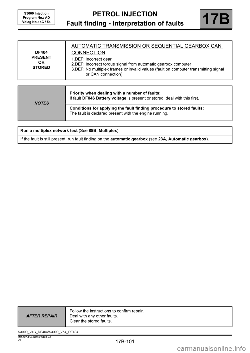
DF404
PRESENT
OR
STORED
AUTOMATIC TRANSMISSION OR SEQUENTIAL GEARBOX CAN
CONNECTION
1.DEF: Incorrect gear
2.DEF: Incorrect torque signal from automatic gearbox computer
3.DEF: No multiplex frames or invalid values (fault on computer transmitting signal
or CAN connection)
NOTESPriority when dealing with a number of faults:
If fault DF046 Battery voltage is present or stored, deal with this first.
Conditions for applying the fault finding procedure to stored faults:
The fault is declared present with the engine running.
Run a multiplex network test (See88B, Multiplex).
If the fault is still present, run fault finding on the automatic gearbox (see 23A, Automatic gearbox).
AFTER REPAIRFollow the instructions to confirm repair.
Deal with any other faults.
Clear the stored faults.
S3000_V4C_DF404/S3000_V54_DF404
Page 106 of 230

PETROL INJECTION
Fault finding - Interpretation of faults
17B
17B-106
PETROL INJECTION
Fault finding - Interpretation of faults
17B
17B-106V9 MR-372-J84-17B050$423.mif
S3000 Injection
Program No.: AD
Vdiag No.: 4C / 54
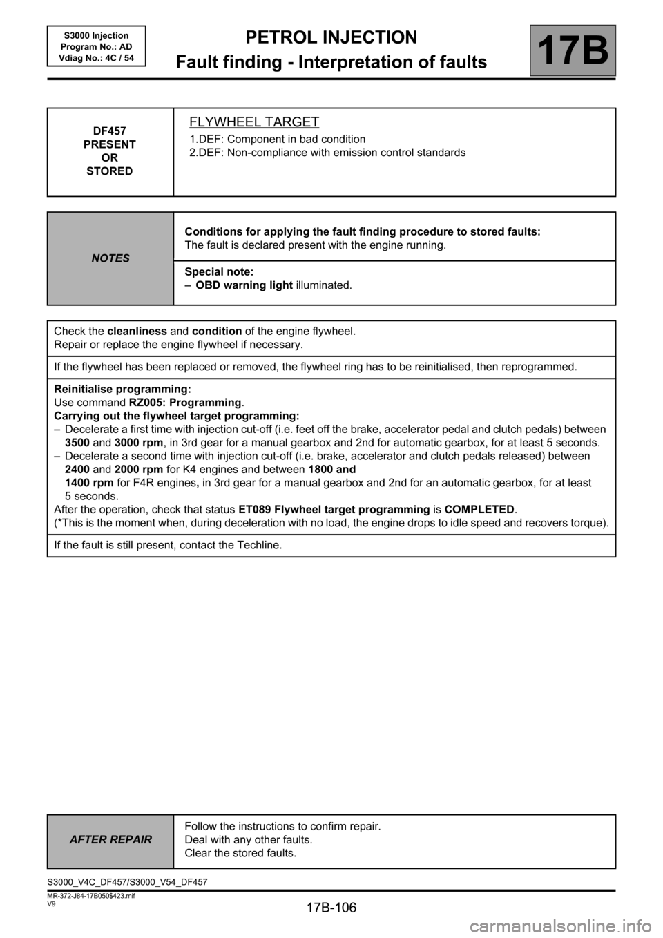
DF457
PRESENT
OR
STOREDFLYWHEEL TARGET
1.DEF: Component in bad condition
2.DEF: Non-compliance with emission control standards
NOTESConditions for applying the fault finding procedure to stored faults:
The fault is declared present with the engine running.
Special note:
–OBD warning light illuminated.
Check the cleanliness and condition of the engine flywheel.
Repair or replace the engine flywheel if necessary.
If the flywheel has been replaced or removed, the flywheel ring has to be reinitialised, then reprogrammed.
Reinitialise programming:
Use command RZ005: Programming.
Carrying out the flywheel target programming:
– Decelerate a first time with injection cut-off (i.e. feet off the brake, accelerator pedal and clutch pedals) between
3500 and 3000 rpm, in 3rd gear for a manual gearbox and 2nd for automatic gearbox, for at least 5 seconds.
– Decelerate a second time with injection cut-off (i.e. brake, accelerator and clutch pedals released) between
2400and 2000 rpm for K4 engines and between 1800 and
1400 rpm for F4R engines, in 3rd gear for a manual gearbox and 2nd for an automatic gearbox, for at least
5 seconds.
After the operation, check that status ET089 Flywheel target programming is COMPLETED.
(*This is the moment when, during deceleration with no load, the engine drops to idle speed and recovers torque).
If the fault is still present, contact the Techline.
AFTER REPAIRFollow the instructions to confirm repair.
Deal with any other faults.
Clear the stored faults.
S3000_V4C_DF457/S3000_V54_DF457