Wiring RENAULT SCENIC 2011 J95 / 3.G Engine And Peripherals EDC16 Injection Owner's Manual
[x] Cancel search | Manufacturer: RENAULT, Model Year: 2011, Model line: SCENIC, Model: RENAULT SCENIC 2011 J95 / 3.GPages: 236, PDF Size: 1.32 MB
Page 159 of 236
13B-159
DIESEL INJECTION
Fault finding - Interpretation of statuses13B
V10 MR-372-J84-13B150$564.mif
EDC16 INJECTION
Program No.: C1
Vdiag No.: 44, 48 and 4C
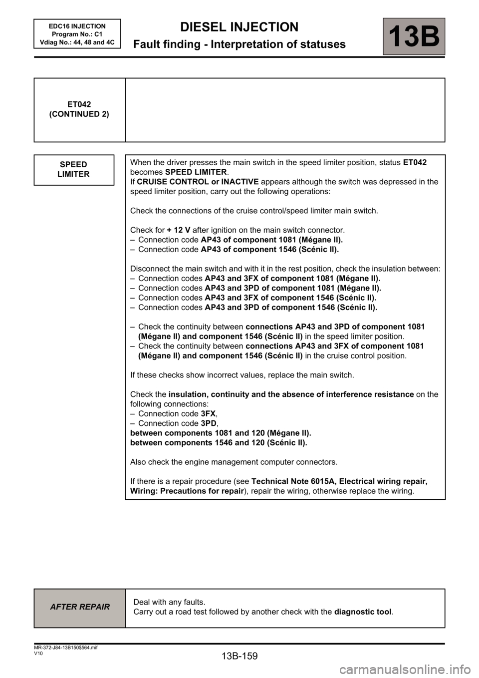
ET042
(CONTINUED 2)
SPEED
LIMITER
When the driver presses the main switch in the speed limiter position, status ET042
becomes SPEED LIMITER.
If CRUISE CONTROL or INACTIVE appears although the switch was depressed in the
speed limiter position, carry out the following operations:
Check the connections of the cruise control/speed limiter main switch.
Check for + 12 V after ignition on the main switch connector.
– Connection code AP43 of component 1081 (Mégane II).
– Connection code AP43 of component 1546 (Scénic II).
Disconnect the main switch and with it in the rest position, check the insulation between:
– Connection codes AP43 and 3FX of component 1081 (Mégane II).
– Connection codes AP43 and 3PD of component 1081 (Mégane II).
– Connection codes AP43 and 3FX of component 1546 (Scénic II).
– Connection codes AP43 and 3PD of component 1546 (Scénic II).
– Check the continuity between connections AP43 and 3PD of component 1081
(Mégane II) and component 1546 (Scénic II) in the speed limiter position.
– Check the continuity between connections AP43 and 3FX of component 1081
(Mégane II) and component 1546 (Scénic II) in the cruise control position.
If these checks show incorrect values, replace the main switch.
Check the insulation, continuity and the absence of interference resistance on the
following connections:
– Connection code 3FX,
– Connection code 3PD,
between components 1081 and 120 (Mégane II).
between components 1546 and 120 (Scénic II).
Also check the engine management computer connectors.
If there is a repair procedure (see Technical Note 6015A, Electrical wiring repair,
Wiring: Precautions for repair), repair the wiring, otherwise replace the wiring.
AFTER REPAIRDeal with any faults.
Carry out a road test followed by another check with the diagnostic tool.
Page 160 of 236
13B-160
DIESEL INJECTION
Fault finding - Interpretation of statuses13B
V10 MR-372-J84-13B150$564.mif
EDC16 INJECTION
Program No.: C1
Vdiag No.: 44, 48 and 4C
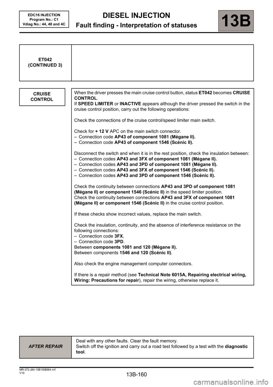
ET042
(CONTINUED 3)
CRUISE
CONTROL
When the driver presses the main cruise control button, status ET042 becomes CRUISE
CONTROL.
If SPEED LIMITER or INACTIVE appears although the driver pressed the switch in the
cruise control position, carry out the following operations:
Check the connections of the cruise control/speed limiter main switch.
Check for + 12 V APC on the main switch connector.
– Connection code AP43 of component 1081 (Mégane II).
– Connection code AP43 of component 1546 (Scénic II).
Disconnect the switch and when it is in the rest position, check the insulation between:
– Connection codes AP43 and 3FX of component 1081 (Mégane II).
– Connection codes AP43 and 3PD of component 1081 (Mégane II).
– Connection codes AP43 and 3FX of component 1546 (Scénic II).
– Connection codes AP43 and 3PD of component 1546 (Scénic II).
Check the continuity between connections AP43 and 3PD of component 1081
(Mégane II) or component 1546 (Scénic II) in the speed limiter position.
Check the continuity between connections AP43 and 3FX of component 1081
(Mégane II) or component 1546 (Scénic II) in the cruise control position.
If these checks show incorrect values, replace the main switch.
Check the insulation, continuity, and the absence of interference resistance on the
following connections:
– Connection code 3FX,
– Connection code3PD.
Between components 1081 and 120 (Mégane II).
Between components 1546 and 120 (Scénic II).
Also check the engine management computer connectors.
If there is a repair method (see Technical Note 6015A, Repairing electrical wiring,
Wiring: Precautions for repair), repair the wiring, otherwise replace it.
AFTER REPAIRDeal with any other faults. Clear the fault memory.
Switch off the ignition and carry out a road test followed by a test with the diagnostic
tool.
Page 169 of 236
13B-169
DIESEL INJECTION
Fault finding - Interpretation of statuses13B
V10 MR-372-J84-13B150$564.mif
EDC16 INJECTION
Program No.: C1
Vdiag No.: 44, 48 and 4C
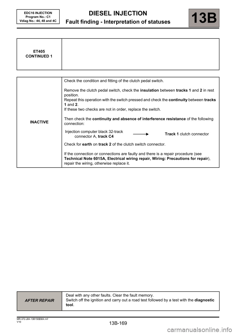
ET405
CONTINUED 1
INACTIVECheck the condition and fitting of the clutch pedal switch.
Remove the clutch pedal switch, check the insulation between tracks 1 and 2 in rest
position.
Repeat this operation with the switch pressed and check the continuity between tracks
1 and 2.
If these two checks are not in order, replace the switch.
Then check the continuity and absence of interference resistance of the following
connection:
Injection computer black 32-track
connector A, track C4Track 1 clutch connector
Check for earth on track 2 of the clutch switch connector.
If the connection or connections are faulty and there is a repair procedure (see
Technical Note 6015A, Electrical wiring repair, Wiring: Precautions for repair),
repair the wiring, otherwise replace it.
AFTER REPAIRDeal with any other faults. Clear the fault memory.
Switch off the ignition and carry out a road test followed by a test with the diagnostic
tool.
Page 176 of 236
13B-176
DIESEL INJECTION
Fault finding - Interpretation of statuses13B
V10 MR-372-J84-13B150$564.mif
EDC16 INJECTION
Program No.: C1
Vdiag No.: 44, 48 and 4C
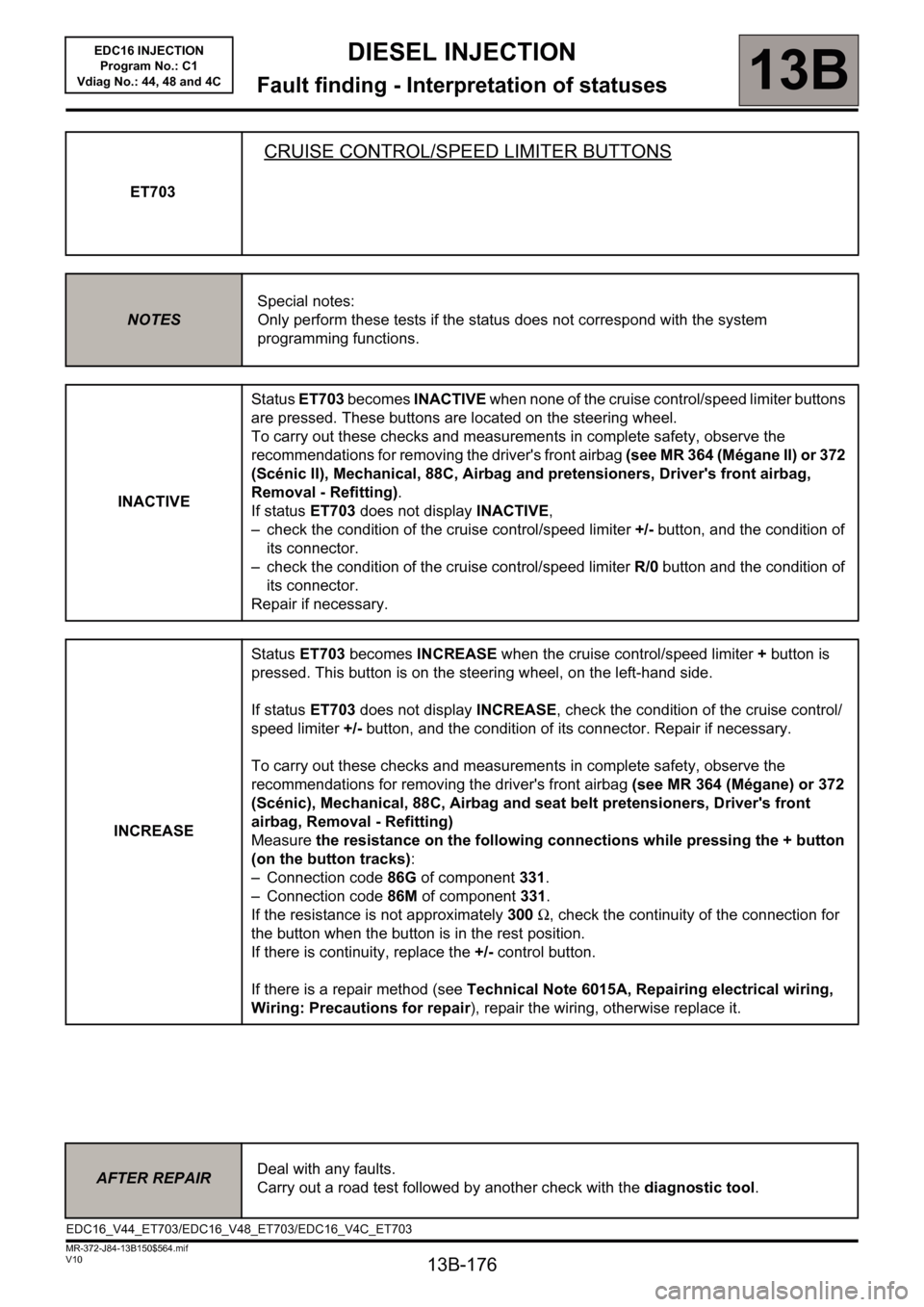
ET703
CRUISE CONTROL/SPEED LIMITER BUTTONS
NOTESSpecial notes:
Only perform these tests if the status does not correspond with the system
programming functions.
INACTIVEStatus ET703 becomes INACTIVE when none of the cruise control/speed limiter buttons
are pressed. These buttons are located on the steering wheel.
To carry out these checks and measurements in complete safety, observe the
recommendations for removing the driver's front airbag (see MR 364 (Mégane II) or 372
(Scénic II), Mechanical, 88C, Airbag and pretensioners, Driver's front airbag,
Removal - Refitting).
If status ET703 does not display INACTIVE,
– check the condition of the cruise control/speed limiter +/- button, and the condition of
its connector.
– check the condition of the cruise control/speed limiter R/0 button and the condition of
its connector.
Repair if necessary.
INCREASEStatus ET703 becomes INCREASE when the cruise control/speed limiter + button is
pressed. This button is on the steering wheel, on the left-hand side.
If status ET703 does not display INCREASE, check the condition of the cruise control/
speed limiter +/- button, and the condition of its connector. Repair if necessary.
To carry out these checks and measurements in complete safety, observe the
recommendations for removing the driver's front airbag (see MR 364 (Mégane) or 372
(Scénic), Mechanical, 88C, Airbag and seat belt pretensioners, Driver's front
airbag, Removal - Refitting)
Measure the resistance on the following connections while pressing the + button
(on the button tracks):
– Connection code86G of component 331.
– Connection code 86M of component 331.
If the resistance is not approximately 300 Ω, check the continuity of the connection for
the button when the button is in the rest position.
If there is continuity, replace the +/- control button.
If there is a repair method (see Technical Note 6015A, Repairing electrical wiring,
Wiring: Precautions for repair), repair the wiring, otherwise replace it.
EDC16_V44_ET703/EDC16_V48_ET703/EDC16_V4C_ET703
AFTER REPAIRDeal with any faults.
Carry out a road test followed by another check with the diagnostic tool.
Page 177 of 236
13B-177
DIESEL INJECTION
Fault finding - Interpretation of statuses13B
V10 MR-372-J84-13B150$564.mif
EDC16 INJECTION
Program No.: C1
Vdiag No.: 44, 48 and 4C
ET703
(CONTINUED 1)
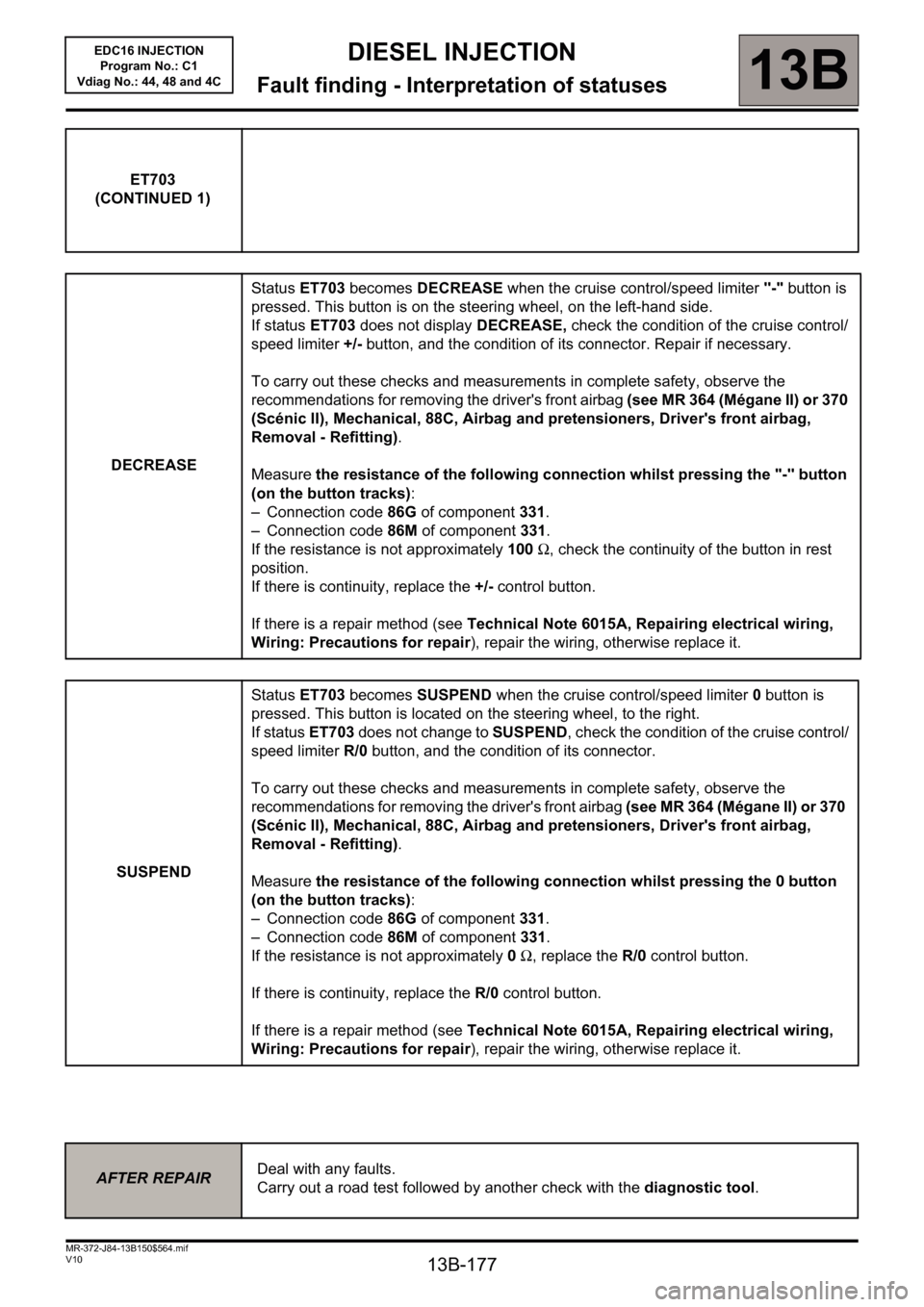
DECREASEStatus ET703 becomes DECREASE when the cruise control/speed limiter "-" button is
pressed. This button is on the steering wheel, on the left-hand side.
If status ET703 does not display DECREASE, check the condition of the cruise control/
speed limiter +/- button, and the condition of its connector. Repair if necessary.
To carry out these checks and measurements in complete safety, observe the
recommendations for removing the driver's front airbag (see MR 364 (Mégane II) or 370
(Scénic II), Mechanical, 88C, Airbag and pretensioners, Driver's front airbag,
Removal - Refitting).
Measure the resistance of the following connection whilst pressing the "-" button
(on the button tracks):
– Connection code86G of component 331.
– Connection code 86M of component 331.
If the resistance is not approximately 100 Ω, check the continuity of the button in rest
position.
If there is continuity, replace the +/- control button.
If there is a repair method (see Technical Note 6015A, Repairing electrical wiring,
Wiring: Precautions for repair), repair the wiring, otherwise replace it.
SUSPENDStatus ET703 becomes SUSPEND when the cruise control/speed limiter 0 button is
pressed. This button is located on the steering wheel, to the right.
If status ET703 does not change to SUSPEND, check the condition of the cruise control/
speed limiter R/0 button, and the condition of its connector.
To carry out these checks and measurements in complete safety, observe the
recommendations for removing the driver's front airbag (see MR 364 (Mégane II) or 370
(Scénic II), Mechanical, 88C, Airbag and pretensioners, Driver's front airbag,
Removal - Refitting).
Measure the resistance of the following connection whilst pressing the 0 button
(on the button tracks):
– Connection code86G of component 331.
– Connection code 86M of component 331.
If the resistance is not approximately 0 Ω, replace the R/0 control button.
If there is continuity, replace the R/0
control button.
If there is a repair method (see Technical Note 6015A, Repairing electrical wiring,
Wiring: Precautions for repair), repair the wiring, otherwise replace it.
AFTER REPAIRDeal with any faults.
Carry out a road test followed by another check with the diagnostic tool.
Page 178 of 236
13B-178
DIESEL INJECTION
Fault finding - Interpretation of statuses13B
V10 MR-372-J84-13B150$564.mif
EDC16 INJECTION
Program No.: C1
Vdiag No.: 44, 48 and 4C
ET703
(CONTINUED 2)
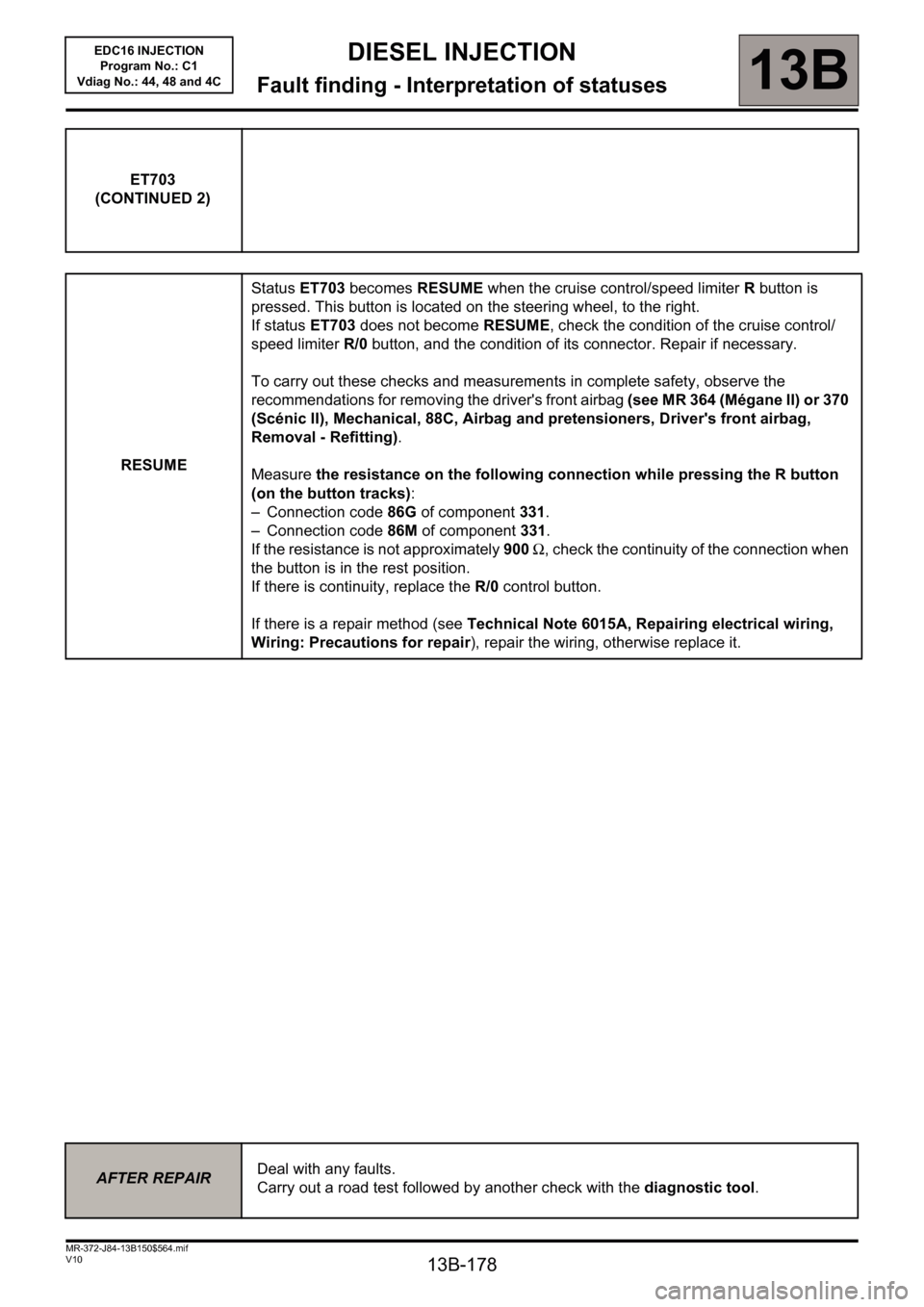
RESUMEStatus ET703 becomes RESUME when the cruise control/speed limiter R button is
pressed. This button is located on the steering wheel, to the right.
If status ET703 does not become RESUME, check the condition of the cruise control/
speed limiter R/0 button, and the condition of its connector. Repair if necessary.
To carry out these checks and measurements in complete safety, observe the
recommendations for removing the driver's front airbag (see MR 364 (Mégane II) or 370
(Scénic II), Mechanical, 88C, Airbag and pretensioners, Driver's front airbag,
Removal - Refitting).
Measure the resistance on the following connection while pressing the R button
(on the button tracks):
– Connection code86G of component 331.
– Connection code 86M of component 331.
If the resistance is not approximately 900 Ω, check the continuity of the connection when
the button is in the rest position.
If there is continuity, replace the R/0 control button.
If there is a repair method (see Technical Note 6015A, Repairing electrical wiring,
Wiring: Precautions for repair), repair the wiring, otherwise replace it.
AFTER REPAIRDeal with any faults.
Carry out a road test followed by another check with the diagnostic tool.
Page 179 of 236
13B-179
DIESEL INJECTION
Fault finding - Interpretation of statuses13B
V10 MR-372-J84-13B150$564.mif
EDC16 INJECTION
Program No.: C1
Vdiag No.: 44, 48 and 4C
EDC16_V44_ET704/EDC16_V48_ET704/EDC16_V4C_ET704/
EDC16_V44_ET705/EDC16_V48_ET705/EDC16_V4C_ET705
AFTER REPAIRDeal with any faults.
Carry out a road test followed by another check with the diagnostic tool.
ET704
ET705
BRAKE SWITCH NO. 1
BRAKE SWITCH NO. 2
NOTESSpecial note:
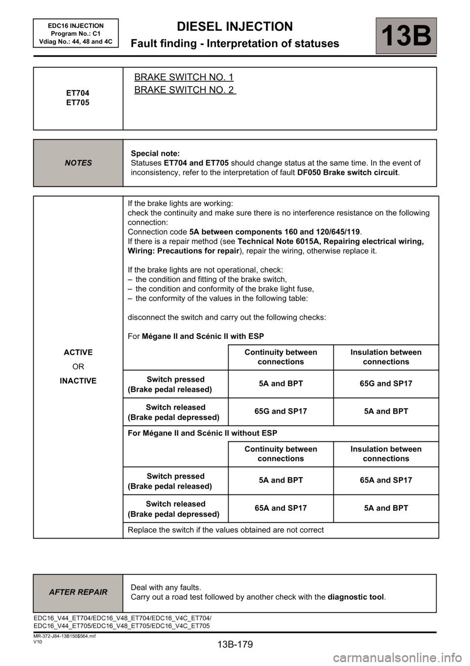
Statuses ET704 and ET705 should change status at the same time. In the event of
inconsistency, refer to the interpretation of fault DF050 Brake switch circuit.
ACTIVE
OR
INACTIVEIf the brake lights are working:
check the continuity and make sure there is no interference resistance on the following
connection:
Connection code 5A between components 160 and 120/645/119.
If there is a repair method (see Technical Note 6015A, Repairing electrical wiring,
Wiring: Precautions for repair), repair the wiring, otherwise replace it.
If the brake lights are not operational, check:
– the condition and fitting of the brake switch,
– the condition and conformity of the brake light fuse,
– the conformity of the values in the following table:
disconnect the switch and carry out the following checks:
For Mégane II and Scénic II with ESP
Continuity between
connectionsInsulation between
connections
Switch pressed
(Brake pedal released)5A and BPT 65G and SP17
Switch released
(Brake pedal depressed)65G and SP17 5A and BPT
For Mégane II and Scénic II without ESP
Continuity between
connectionsInsulation between
connections
Switch pressed
(Brake pedal released)5A and BPT 65A and SP17
Switch released
(Brake pedal depressed)65A and SP17 5A and BPT
Replace the switch if the values obtained are not correct
Page 194 of 236
13B - 194
DIESEL INJECTION
Fault finding - Interpretation of commands13B
V10 MR-372-J84-13B150$752.mif
EDC16 INJECTION
Program No.: C1
Vdiag No: 44, 48 and 4C
AC001
PREHEATING UNIT
NOTESThis command is only carried out if fault DF025 Preheating unit fault finding
connection or DF081 Preheating relay circuit is present or stored and if no other
fault is present.
Refer to the Wiring diagrams Technical Note for the vehicle to locate the fuses and
relays concerned.
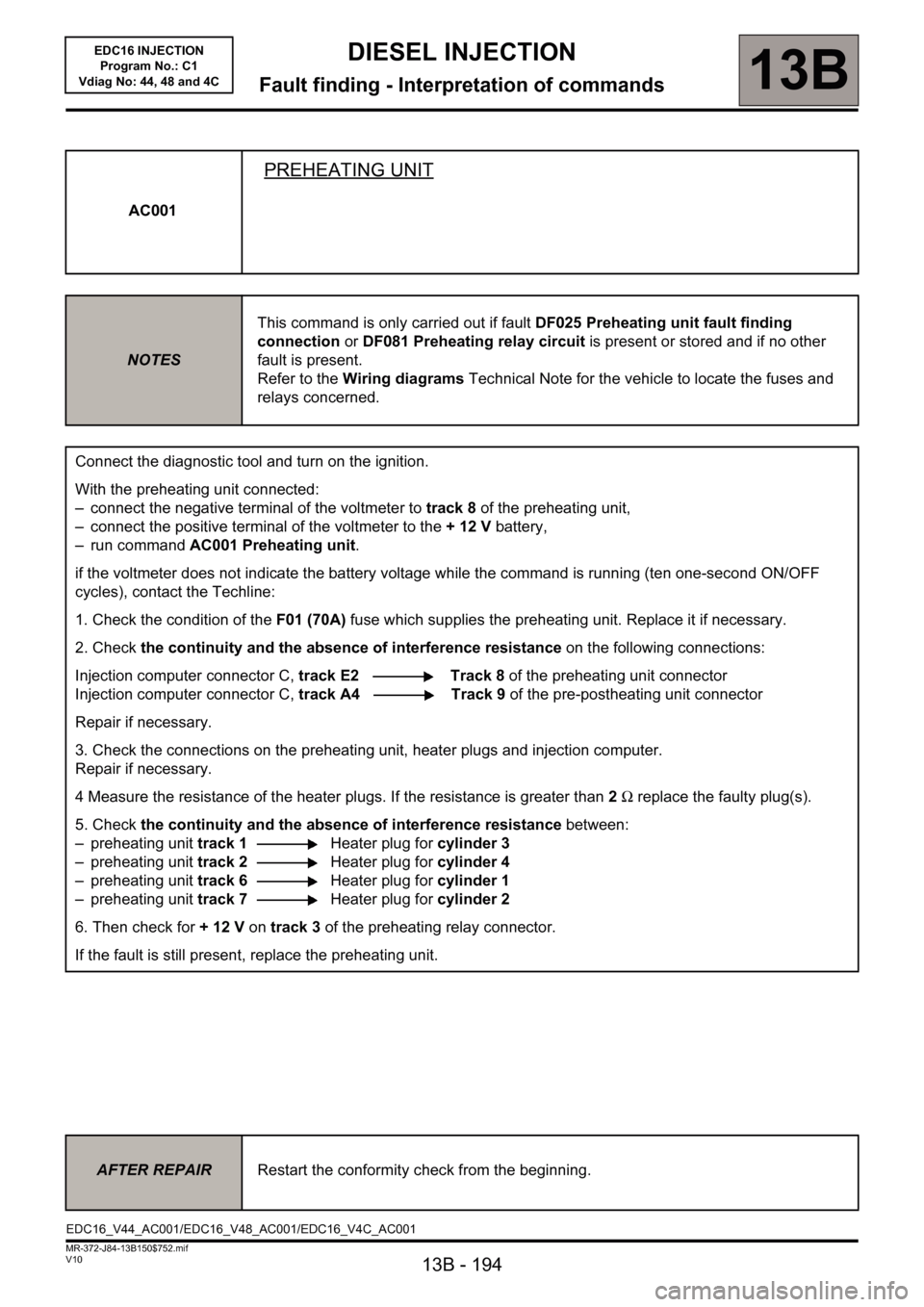
Connect the diagnostic tool and turn on the ignition.
With the preheating unit connected:
– connect the negative terminal of the voltmeter to track 8 of the preheating unit,
– connect the positive terminal of the voltmeter to the + 12 V battery,
– run command AC001 Preheating unit.
if the voltmeter does not indicate the battery voltage while the command is running (ten one-second ON/OFF
cycles), contact the Techline:
1. Check the condition of theF01 (70A) fuse which supplies the preheating unit. Replace it if necessary.
2. Check the continuity and the absence of interference resistance on the following connections:
Injection computer connector C, track E2 Track 8 of the preheating unit connector
Injection computer connector C, track A4 Track 9 of the pre-postheating unit connector
Repair if necessary.
3. Check the connections on the preheating unit, heater plugs and injection computer.
Repair if necessary.
4 Measure the resistance of the heater plugs. If the resistance is greater than 2Ω replace the faulty plug(s).
5. Check the continuity and the absence of interference resistance between:
– preheating unit track 1Heater plug for cylinder 3
– preheating unit track 2Heater plug for cylinder 4
– preheating unit track 6Heater plug for cylinder 1
– preheating unit track 7Heater plug for cylinder 2
6. Then check for +12V on track 3 of the preheating relay connector.
If the fault is still present, replace the preheating unit.
AFTER REPAIRRestart the conformity check from the beginning.
EDC16_V44_AC001/EDC16_V48_AC001/EDC16_V4C_AC001
Page 204 of 236
13B-204
MR-372-J84-13B150$846.mif
V10
DIESEL INJECTION
Fault finding - Fault finding chart13B
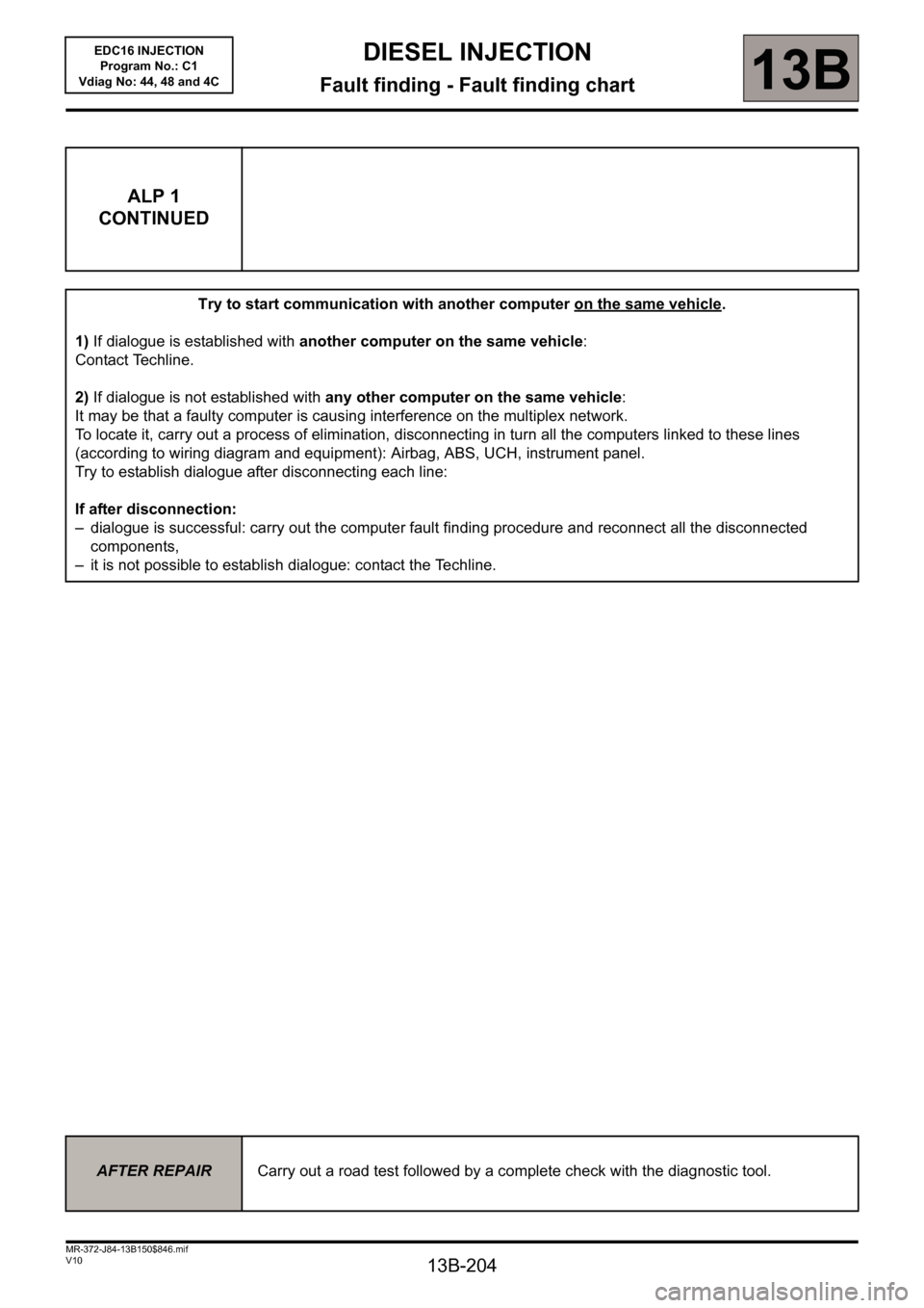
ALP 1
CONTINUED
Try to start communication with another computer on the same vehicle.
1)If dialogue is established with another computer on the same vehicle:
Contact Techline.
2)If dialogue is not established with any other computer on the same vehicle:
It may be that a faulty computer is causing interference on the multiplex network.
To locate it, carry out a process of elimination, disconnecting in turn all the computers linked to these lines
(according to wiring diagram and equipment): Airbag, ABS, UCH, instrument panel.
Try to establish dialogue after disconnecting each line:
If after disconnection:
– dialogue is successful: carry out the computer fault finding procedure and reconnect all the disconnected
components,
– it is not possible to establish dialogue: contact the Techline.
AFTER REPAIRCarry out a road test followed by a complete check with the diagnostic tool.
EDC16 INJECTION
Program No.: C1
Vdiag No: 44, 48 and 4C
Page 210 of 236
13B-210
MR-372-J84-13B150$846.mif
V10
DIESEL INJECTION
Fault finding - Fault finding chart13B
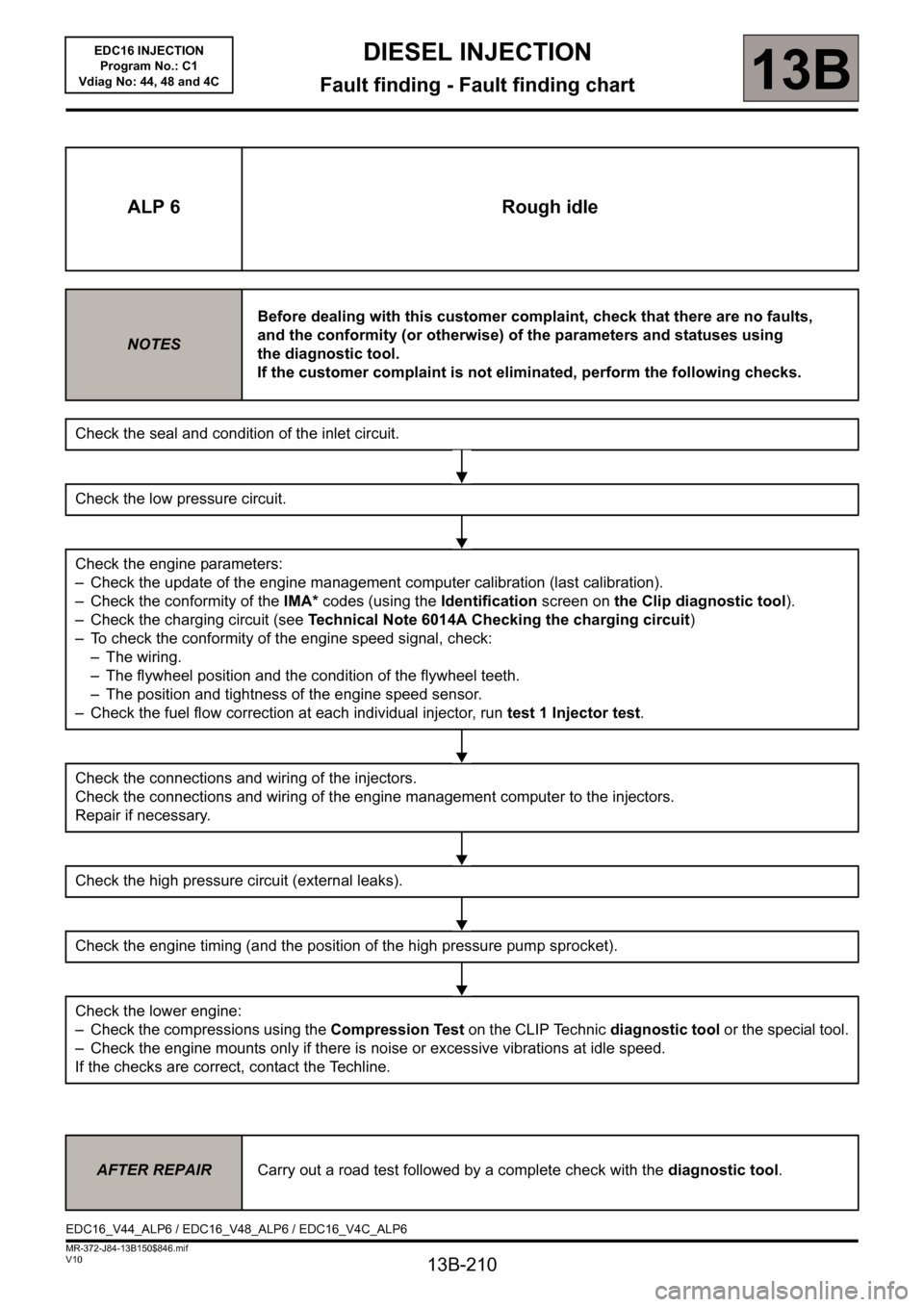
ALP 6 Rough idle
NOTESBefore dealing with this customer complaint, check that there are no faults,
and the conformity (or otherwise) of the parameters and statuses using
the diagnostic tool.
If the customer complaint is not eliminated, perform the following checks.
Check the seal and condition of the inlet circuit.
Check the low pressure circuit.
Check the engine parameters:
– Check the update of the engine management computer calibration (last calibration).
– Check the conformity of the IMA* codes (using the Identification screen on the Clip diagnostic tool).
– Check the charging circuit (see Technical Note 6014A Checking the charging circuit)
– To check the conformity of the engine speed signal, check:
– The wiring.
– The flywheel position and the condition of the flywheel teeth.
– The position and tightness of the engine speed sensor.
– Check the fuel flow correction at each individual injector, run test 1 Injector test.
Check the connections and wiring of the injectors.
Check the connections and wiring of the engine management computer to the injectors.
Repair if necessary.
Check the high pressure circuit (external leaks).
Check the engine timing (and the position of the high pressure pump sprocket).
Check the lower engine:
– Check the compressions using the Compression Test on the CLIP Technic diagnostic tool or the special tool.
– Check the engine mounts only if there is noise or excessive vibrations at idle speed.
If the checks are correct, contact the Techline.
AFTER REPAIRCarry out a road test followed by a complete check with the diagnostic tool.
EDC16_V44_ALP6 / EDC16_V48_ALP6 / EDC16_V4C_ALP6EDC16 INJECTION
Program No.: C1
Vdiag No: 44, 48 and 4C