RENAULT SCENIC 2011 J95 / 3.G Engine And Peripherals EDC16 Workshop Manual
Manufacturer: RENAULT, Model Year: 2011, Model line: SCENIC, Model: RENAULT SCENIC 2011 J95 / 3.GPages: 365, PDF Size: 2.11 MB
Page 1 of 365
1Engine and peripherals
V13 MR-372-J84-13B200$TOC.mif
V13
13B
"The repair procedures given by the manufacturer in this document are based on the
technical specifications current when it was prepared.
The procedures may be modified as a result of changes introduced by the
manufacturer in the production of the various component units and accessories from
which his vehicles are constructed."
V13
All rights reserved by Renault s.a.s.
Edition Anglaise
Copying or translating, in part or in full, of this document or use of the service part
reference numbering system is forbidden without the prior written authority of
Renault s.a.s.
© Renault s.a.s. 2011
DIESEL INJECTION
EDC16
Program No.: C1
Vdiag no.: 18, 1C, 20, 50, 58, 5C
Fault finding – Introduction 13B - 2
Fault finding – Cleanliness guidelines 13B - 9
Fault finding – System operation 13B - 11
Fault finding – Replacement of components 13B - 21
Fault finding – Configuration and programming 13B - 26
Fault finding – Fault summary table 13B - 27
Fault finding – Interpretation of faults 13B - 33
Fault finding – Conformity check 13B - 161
Fault finding – Status summary table 13B - 162
Fault finding – Interpretation of statuses 13B - 164
Fault finding – Parameter summary table 13B - 210
Fault finding – Interpretation of parameters 13B - 214
Fault finding – Command summary table 13B - 291
Fault finding – Interpretation of commands 13B - 292
Fault finding – Customer complaints 13B - 317
Fault finding – Fault Finding Chart 13B - 318
Fault finding – Tests 13B - 338
Fault finding – Glossary 13B - 365
Page 2 of 365
13B-2
MR-372-J84-13B200$036.mif
V13
13B
DIESEL INJECTION
Fault finding – Introduction
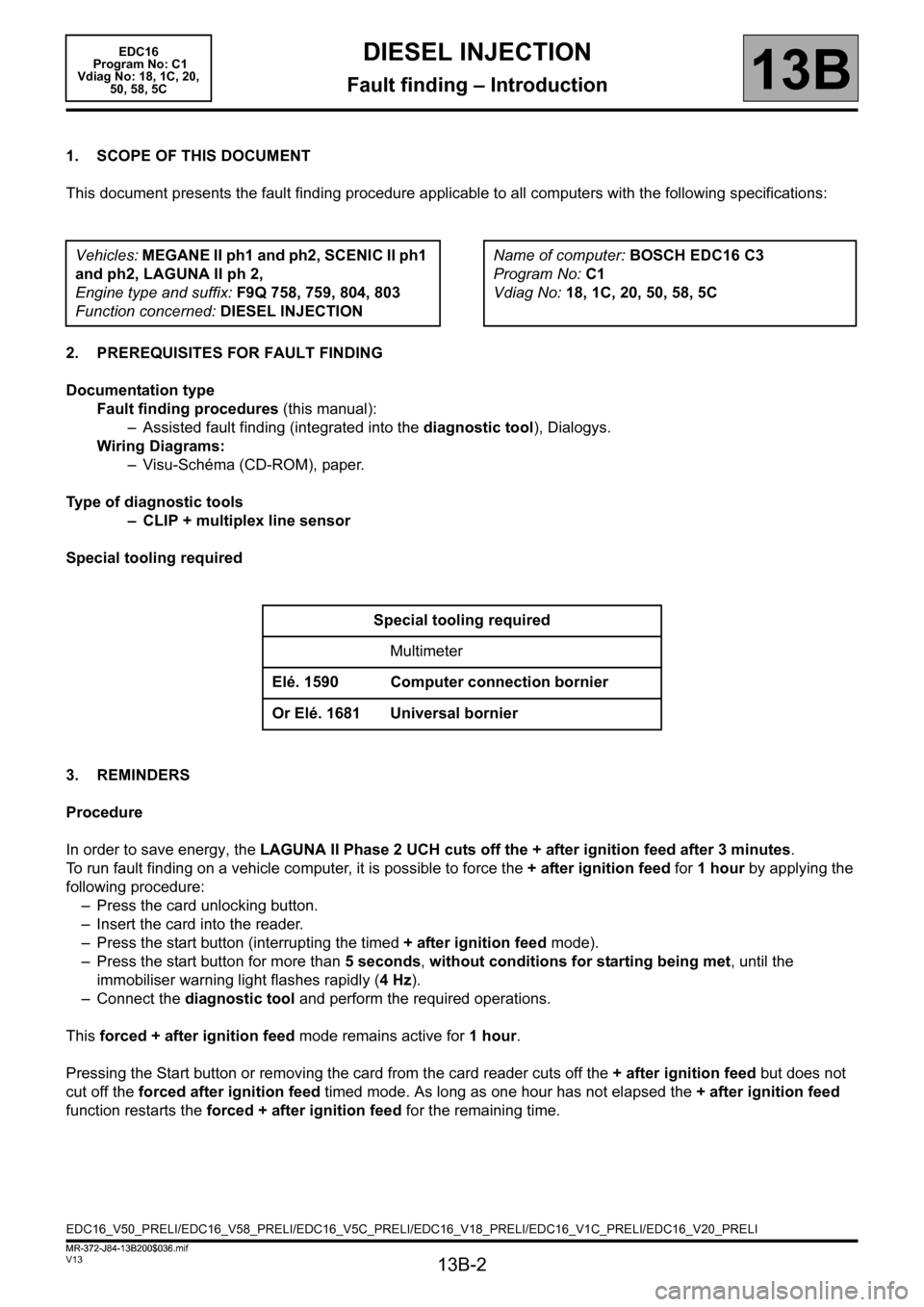
1. SCOPE OF THIS DOCUMENT
This document presents the fault finding procedure applicable to all computers with the following specifications:
2. PREREQUISITES FOR FAULT FINDING
Documentation type
Fault finding procedures (this manual):
– Assisted fault finding (integrated into the diagnostic tool), Dialogys.
Wiring Diagrams:
– Visu-Schéma (CD-ROM), paper.
Type of diagnostic tools
– CLIP + multiplex line sensor
Special tooling required
3. REMINDERS
Procedure
In order to save energy, the LAGUNA II Phase 2 UCH cuts off the + after ignition feed after 3 minutes.
To run fault finding on a vehicle computer, it is possible to force the + after ignition feed for 1 hour by applying the
following procedure:
– Press the card unlocking button.
– Insert the card into the reader.
– Press the start button (interrupting the timed + after ignition feed mode).
– Press the start button for more than 5 seconds, without conditions for starting being met, until the
immobiliser warning light flashes rapidly (4Hz).
– Connect the diagnostic tool and perform the required operations.
This forced + after ignition feed mode remains active for 1 hour.
Pressing the Start button or removing the card from the card reader cuts off the + after ignition feed but does not
cut off the forced after ignition feed timed mode. As long as one hour has not elapsed the + after ignition feed
function restarts the forced + after ignition feed for the remaining time. Vehicles: MEGANE II ph1 and ph2, SCENIC II ph1
and ph2, LAGUNA II ph 2,
Engine type and suffix: F9Q 758, 759, 804, 803
Function concerned: DIESEL INJECTIONName of computer: BOSCH EDC16 C3
Program No: C1
Vdiag No: 18, 1C, 20, 50, 58, 5C
Special tooling required
Multimeter
Elé. 1590 Computer connection bornier
Or Elé. 1681 Universal bornier
EDC16_V50_PRELI/EDC16_V58_PRELI/EDC16_V5C_PRELI/EDC16_V18_PRELI/EDC16_V1C_PRELI/EDC16_V20_PRELI EDC16
Program No: C1
Vdiag No: 18, 1C, 20,
50, 58, 5C
MR-372-J84-13B200$036.mif
Page 3 of 365
13B-3
MR-372-J84-13B200$036.mif
V13
DIESEL INJECTION
Fault finding – Introduction
EDC16
Program No: C1
Vdiag No: 18, 1C, 20,
50, 58, 5C
13B
Faults
Faults are declared as either present or stored (depending on whether they appeared in a certain context and have
disappeared since, or whether they remain present but have not been diagnosed within the current context).
The present or stored status of faults should be taken into consideration when the diagnostic tool is switched on
after the + after ignition feed (without any system components being active).
For a present fault, apply the procedure described in the Interpretation of faults section.
For a stored fault, note the faults displayed and apply the instructions in the Notes section.
If the fault is confirmed when the instructions in the Notes section are applied, the fault is present. Deal with the
fault
If the fault is not confirmed, check:
– the electrical connections that correspond to the fault,
– the connectors for this connection,
– the resistance of the component detected as faulty,
– the condition of the wires.
Refer to paragraphs 3.1 Checking the wiring and 3.2 Checking the connectors.
Conformity check
The aim of the conformity check is to check data that does not produce a fault on the diagnostic tool because the
data is inconsistent. Therefore, this stage is used to:
– carry out fault finding on faults that do not have a fault display, and which may correspond to a customer
complaint.
– check that the system is operating correctly and that there is no risk of a fault recurring after repairs.
This section gives the fault finding procedures for statuses and parameters and the conditions for checking them.
If a status is not behaving normally or a parameter is outside the permitted tolerance values, consult the
corresponding fault finding page.
Customer complaints – Fault finding chart
If the test with the diagnostic tool is OK but the customer complaint is still present, the fault should be processed by
customer complaints.
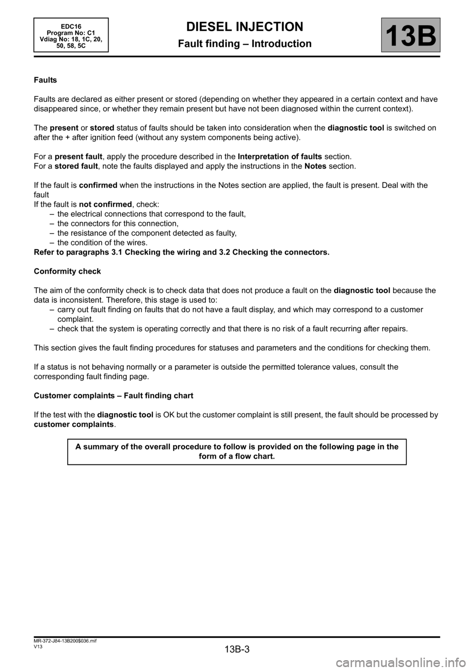
A summary of the overall procedure to follow is provided on the following page in the
form of a flow chart.
Page 4 of 365
13B-4
MR-372-J84-13B200$036.mif
V13
EDC16
Program No: C1
Vdiag No: 18, 1C, 20,
50, 58, 5CDIESEL INJECTION
Fault finding – Introduction13B
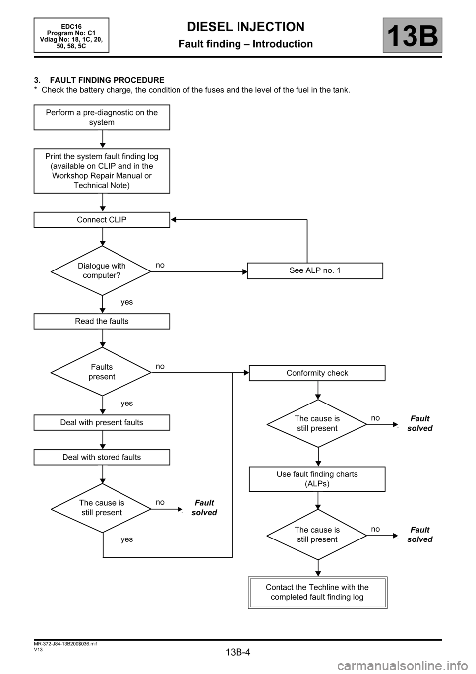
3. FAULT FINDING PROCEDURE
* Check the battery charge, the condition of the fuses and the level of the fuel in the tank.
Perform a pre-diagnostic on the
system
Print the system fault finding log
(available on CLIP and in the
Workshop Repair Manual or
Technical Note)
Connect CLIP
no
Dialogue with
computer?
yes
Read the faults
no
Faults
present
yes
Deal with present faults
Deal with stored faults
no
The cause is
still presentFault
solved
yes
See ALP no. 1
Conformity check
no
The cause is
still presentFault
solved
Use fault finding charts
(ALPs)
no
The cause is
still presentFault
solved
Contact the Techline with the
completed fault finding log
Page 5 of 365
13B-5
MR-372-J84-13B200$036.mif
V13
DIESEL INJECTION
Fault finding – Introduction
EDC16
Program No: C1
Vdiag No: 18, 1C, 20,
50, 58, 5C
13B
3. FAULT FINDING PROCEDURE (continued)
3.1 Checking the wiring
Fault finding problems
Disconnecting the connectors and/or manipulating the wiring harness may temporarily remove the cause of a fault.
Visual inspection
Look for damage under the bonnet and in the passenger compartment.
Carefully check the protectors, insulation, and routing of the wiring, as well as the mountings.
Tactile inspection
When manoeuvring the wiring, either use the diagnostic tool to detect a change in status, from "stored" to
"present", or the multimeter to view the status changes.
Make sure that the connectors are properly locked.
Apply light pressure to the connectors.
Twist the wiring harness.
Checking earth insulation
This check is carried out by measuring the voltage (multimeter in voltmeter mode) between the suspect connection
and the 12 V or 5V feed. The correct measured value is 0V.
Checking insulation against + 12 V or + 5 V
This check is carried out by measuring the voltage (multimeter in voltmeter mode) between the suspect connection
and the earth. In the first instance, the earth may be taken on the chassis. The correct measured value is 0V.
Continuity check
A continuity check is carried out by measuring the resistance (multimeter in ohmmeter mode), with the connectors
disconnected at both ends. The expected result is: 1Ω±1Ω for each connection. The line must be fully checked,
and the intermediate connections are only included in the method if this saves time during the fault finding
procedure. The continuity check on the multiplex lines must be carried out on both wires. The measured value
should be 1Ω±1Ω.
Checking the supply
This check may be carried out using a test light (21 W or 5W depending on the maximum authorised charge).
Page 6 of 365
13B-6
MR-372-J84-13B200$036.mif
V13
DIESEL INJECTION
Fault finding – Introduction
EDC16
Program No: C1
Vdiag No: 18, 1C, 20,
50, 58, 5C
13B
3.2 Checking the connectors
1. Visual inspection of the connection:
– Check that the connector is connected correctly and that the male and female parts of the connection are
correctly coupled.
2. Visual inspection of the area around the connection:
– Check the condition of the mounting (pin, strap, adhesive tape, etc.) if the connectors are attached to the
vehicle.
– Check that there is no damage to the wiring trim (sheath, foam, adhesive tape, etc.) near the wiring.
– Check that there is no damage to the electrical wires at the connector outputs, in particular on the insulating
material (wear, cuts, burns, etc.).
Disconnect the connector to continue the checks.
3. Visual inspection of the plastic casing:
– Check that there is no mechanical damage (casing crushed, split, broken, etc.), in particular to the fragile
components (lever, lock, sockets, etc.).
– Check that there is no heat damage (casing melted, darker, deformed, etc.).
– Check that there are no stains (grease, mud, liquid, etc.).
4. Visual inspection of the metal contacts:
(The female contact is called CLIP. The male contact is called TAB.)
– Check that there are no bent contacts (the contact is not inserted correctly and can come out of the back of the
connector). The contact comes out of the connector when the wire is pulled gently.
– Check that there is no damage (folded tabs, clips open too wide, blackened or melted contact, etc.).
– Check that there is no oxidation on the metal contacts. Note:
Carry out each requested check visually. Do not remove a connector if it is not required.
Note:
Repeated connections and disconnections alter the functionality of the connectors and increase the risk of poor
electrical contact. Limit the number of connections/disconnections as much as possible.
Note:
The check is carried out on the 2 parts of the connection. There may be two types of connection:
– Connector/Connector.
– Connector/Device.
Page 7 of 365
13B-7
MR-372-J84-13B200$036.mif
V13
DIESEL INJECTION
Fault finding – Introduction
EDC16
Program No: C1
Vdiag No: 18, 1C, 20,
50, 58, 5C
13B
Visual inspection of the sealing:
(Only for watertight connectors)
Check for the seal on the connection (between the 2 parts of the connection).
– Check the seal at the back of the connectors:
– For unit
joints (1 for each wire), check that the unit joints are present on each electrical wire and that they are
correctly positioned in the opening (level with the housing). Check that plugs are present on openings which are
not used.
– For a grommet
seal (one seal which covers the entire internal surface of the connector), check that the seal is
present.
– For gel
seals, check for gel in all of the sockets without removing the excess or any protruding sections (it does
not matter if there is gel on the contacts).
– For hotmelt
sealing (heat-shrink sheath with glue), check that the sheath has contracted correctly on the rear of
the connectors and electrical wires, and that the hardened glue comes out of the side of the wire.
– Check that there is no damage to any of the seals (cuts, burns, significant deformation, etc.).
If a fault is detected, consult Technical Note 6015A, Repairing electrical wiring.
4. FAULT FINDING LOG
You will always be asked for this log:
– when requesting technical assistance from Techline,
– for approval requests when replacing parts for which approval is mandatory,
– to be attached to monitored parts for which reimbursement is requested. The log is needed for warranty
reimbursement, and enables better analysis of the parts removed.
5. SAFETY INSTRUCTIONS
Safety rules must be observed during any work on a component to prevent any damage or injury:
– check the battery voltage to avoid incorrect operation of computer functions,
– Use the proper tools. IMPORTANTIMPORTANT
Any fault on a complex system requires thorough fault finding with the appropriate tools. The
FAULT FINDING LOG, which should be completed during the procedure, enables you to keep
track of the procedure which is carried out. It is an essential document when consulting the
manufacturer.
IT IS THEREFORE MANDATORY TO FILL OUT A FAULT FINDING LOG EACH TIME FAULT FINDING IS
CARRIED OUT.
Page 8 of 365

13B-8
MR-372-J84-13B200$036.mif
V13
DIESEL INJECTION
Fault finding – Introduction
EDC16
Program No: C1
Vdiag No: 18, 1C, 20,
50, 58, 5C
13B
6. CLEANLINESS ADVICE TO FOLLOW WHEN CARRYING OUT OPERATIONS ON THE HIGH PRESSURE
DIRECT INJECTION SYSTEM
Risks relating to contamination
The system is highly sensitive to contamination. The risks associated with contamination are:
– damage to or destruction of the high pressure injection system and the engine,
– a component seizing or leaking.
All After-Sales operations must be performed under very clean conditions. This means that no impurities (particles a
few microns in size) should be allowed to penetrate the system during dismantling or get into the circuits via the fuel
unions.
The cleanliness principle must be applied from the filter to the injectors.
Page 9 of 365
13B-9
MR-372-J84-13B200$072.mif
V13
13B
DIESEL INJECTION
Fault finding – Cleanliness guidelines
I - HAZARDS ASSOCIATED WITH CONTAMINATION
The high pressure direct injection system is highly sensitive to contamination. The risks associated with
contamination are:
– damage to or destruction of the high pressure injection system,
– components jamming,
– a component leaking.
All After-Sales operations must be performed under very clean conditions. This means that no impurities (particles a
few microns in size) should have entered the system during dismantling.
The cleanliness principle must be applied from the filter to the injectors.
What are the sources of contamination?
– metal or plastic swarf,
–paint,
–fibres:
– from cardboard,
– from brushes,
–from paper,
– from clothing,
– from cloths,
– foreign bodies such as hair,
–ambient air
–etc.
II - INSTRUCTIONS TO BE FOLLOWED PRIOR TO ALL OPERATIONS
Check that you have plugs for the unions to be opened (set of plugs available from the Parts Department). The plugs
are single-use only. After use, they must be discarded (once used they are soiled and cleaning is not sufficient to
make them reusable). Unused plugs must be discarded.
Check that you have hermetically resealable plastic bags for storing removed parts. Parts stored in this way will be
less susceptible to the risk of contamination. The bags are to be used once only, and discarded after use. IMPORTANT
Cleaning the engine using a high pressure washer is prohibited because of the risk of damaging connections.
In addition, moisture may collect in the connectors and create electrical connection faults.
IMPORTANT
Before any work is carried out on the high pressure injection system, protect:
– the accessories and timing belts,
– the electrical accessories, (starter, alternator, electric power-assisted steering pump),
– the flywheel surface, to prevent any diesel from running onto the clutch friction plate.
EDC16
Program No: C1
Vdiag No: 18, 1C, 20,
50, 58, 5C
MR-372-J84-13B200$072.mif
Page 10 of 365
13B-10
MR-372-J84-13B200$072.mif
V13
DIESEL INJECTION
Fault finding – Cleanliness guidelines
EDC16
Program No: C1
Vdiag No: 18, 1C, 20,
50, 58, 5C
13B
Use lint-free cleaning cloths (cloth part number 77 11 211 707). Using normal cloth or paper is prohibited. They are
not lint-free and could contaminate the fuel circuit. Each cloth should only be used once.
Use fresh cleaning agent for each operation (used cleaning agent is contaminated). Pour it into an uncontaminated
container.
For each operation, use a clean brush in good condition (the brush must not shed its bristles).
Use a brush and cleaning agent to clean the unions to be opened.
Blast compressed air over the cleaned parts (tools, workbench, the parts, unions and injection system zones).
Check that no bristles remain.
Wash your hands before and during the operation if necessary.
When wearing leather protective gloves cover them with latex gloves to prevent contamination.
III - INSTRUCTIONS TO BE FOLLOWED DURING THE OPERATION
As soon as the circuit is open, all openings must be plugged to prevent impurities from entering the system. The
plugs to be used are available from the Parts Department. The plugs must not be reused under any circumstances.
Seal the pouch shut, even if it has to be opened shortly afterwards. Ambient air carries contamination.
All components removed from the injection system must be stored in a hermetically sealed plastic bag once they
have been plugged.
Using a brush, cleaning agent, air gun, sponge or normal cloth is strictly prohibited once the circuit has been
opened. These items could allow contamination to enter the system.
A new component replacing an old one must not be removed from its packaging until it is to be fitted to the vehicle.