change time RENAULT SCENIC 2011 J95 / 3.G Engine And Peripherals EDC16 Injection Workshop Manual
[x] Cancel search | Manufacturer: RENAULT, Model Year: 2011, Model line: SCENIC, Model: RENAULT SCENIC 2011 J95 / 3.GPages: 236, PDF Size: 1.32 MB
Page 152 of 236

13B-152
DIESEL INJECTION
Fault finding - Interpretation of statuses13B
V10 MR-372-J84-13B150$564.mif
EDC16 INJECTION
Program No.: C1
Vdiag No.: 44, 48 and 4C
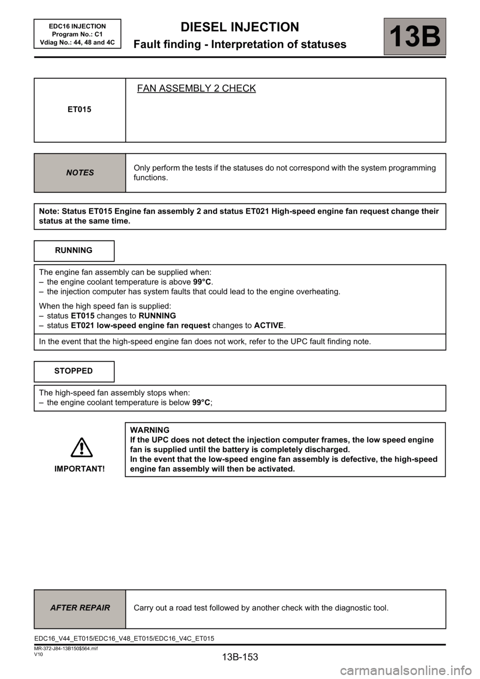
ET014
FAN ASSEMBLY 1 CHECK
NOTESOnly perform the tests if the statuses do not correspond with the system programming
functions.
Note: Status ET022 Low-speed engine fan request and status ET014 Engine fan assembly check 1 change
their status at the same time.
RUNNING
The low-speed fan assembly is supplied in three scenarios:
– the engine coolant temperature is above 89°C,
– the air conditioning is operating,
– the injection computer has system faults that could lead to the engine overheating.
When the low-speed fan assembly is supplied:
– status ET014 changes to RUNNING
– status ET022 low-speed engine fan request changes to ACTIVE.
In the event that the low-speed engine fan does not work, refer to the UPC fault finding note.
STOPPED
The low-speed fan assembly stops when:
– the engine coolant temperature is below 89°C,
– no air conditioning request made by the driver.
IMPORTANT!WARNING
If the UPC does not detect the injection computer frames, the low-speed engine
fan assembly is supplied until the battery is completely discharged.
In the event that the low-speed engine fan assembly is defective, the high-speed
engine fan assembly will then be activated.
AFTER REPAIRCarry out a road test followed by another check with the diagnostic tool.
EDC16_V44_ET014/EDC16_V48_ET014/EDC16_V4C_ET014
Page 153 of 236

13B-153
DIESEL INJECTION
Fault finding - Interpretation of statuses13B
V10 MR-372-J84-13B150$564.mif
EDC16 INJECTION
Program No.: C1
Vdiag No.: 44, 48 and 4C
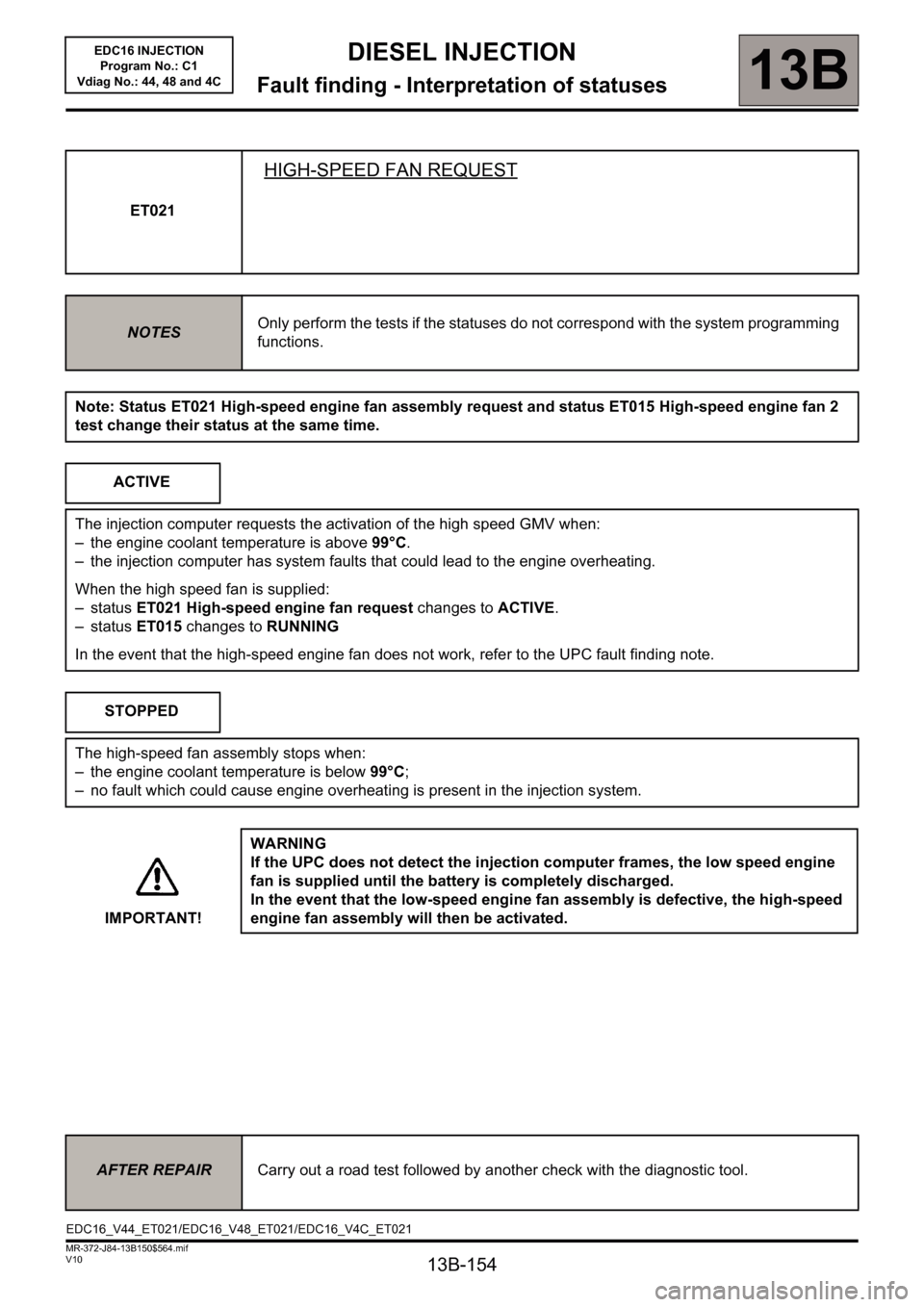
ET015
FAN ASSEMBLY 2 CHECK
NOTESOnly perform the tests if the statuses do not correspond with the system programming
functions.
Note: Status ET015 Engine fan assembly 2 and status ET021 High-speed engine fan request change their
status at the same time.
RUNNING
The engine fan assembly can be supplied when:
– the engine coolant temperature is above 99°C.
– the injection computer has system faults that could lead to the engine overheating.
When the high speed fan is supplied:
– status ET015 changes to RUNNING
– status ET021 low-speed engine fan request changes to ACTIVE.
In the event that the high-speed engine fan does not work, refer to the UPC fault finding note.
STOPPED
The high-speed fan assembly stops when:
– the engine coolant temperature is below 99°C;
IMPORTANT!WARNING
If the UPC does not detect the injection computer frames, the low speed engine
fan is supplied until the battery is completely discharged.
In the event that the low-speed engine fan assembly is defective, the high-speed
engine fan assembly will then be activated.
AFTER REPAIRCarry out a road test followed by another check with the diagnostic tool.
EDC16_V44_ET015/EDC16_V48_ET015/EDC16_V4C_ET015
Page 154 of 236

13B-154
DIESEL INJECTION
Fault finding - Interpretation of statuses13B
V10 MR-372-J84-13B150$564.mif
EDC16 INJECTION
Program No.: C1
Vdiag No.: 44, 48 and 4C
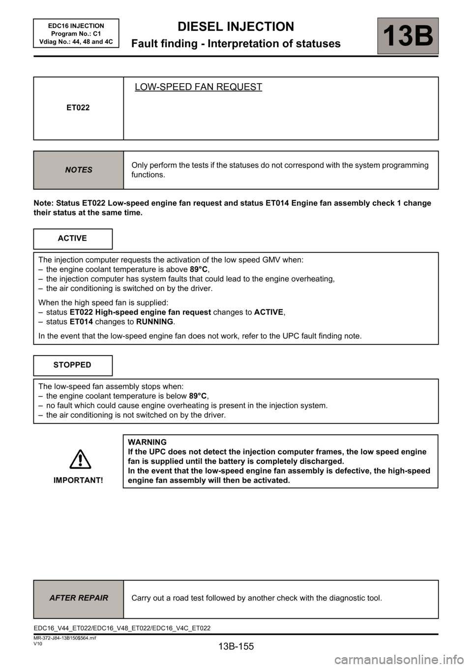
ET021
HIGH-SPEED FAN REQUEST
NOTESOnly perform the tests if the statuses do not correspond with the system programming
functions.
Note: Status ET021 High-speed engine fan assembly request and status ET015 High-speed engine fan 2
test change their status at the same time.
ACTIVE
The injection computer requests the activation of the high speed GMV when:
– the engine coolant temperature is above 99°C.
– the injection computer has system faults that could lead to the engine overheating.
When the high speed fan is supplied:
– status ET021 High-speed engine fan request changes to ACTIVE.
– status ET015 changes to RUNNING
In the event that the high-speed engine fan does not work, refer to the UPC fault finding note.
STOPPED
The high-speed fan assembly stops when:
– the engine coolant temperature is below 99°C;
– no fault which could cause engine overheating is present in the injection system.
IMPORTANT!WARNING
If the UPC does not detect the injection computer frames, the low speed engine
fan is supplied until the battery is completely discharged.
In the event that the low-speed engine fan assembly is defective, the high-speed
engine fan assembly will then be activated.
AFTER REPAIRCarry out a road test followed by another check with the diagnostic tool.
EDC16_V44_ET021/EDC16_V48_ET021/EDC16_V4C_ET021
Page 155 of 236

13B-155
DIESEL INJECTION
Fault finding - Interpretation of statuses13B
V10 MR-372-J84-13B150$564.mif
EDC16 INJECTION
Program No.: C1
Vdiag No.: 44, 48 and 4C
Note: Status ET022 Low-speed engine fan request and status ET014 Engine fan assembly check 1 change
their status at the same time.ET022
LOW-SPEED FAN REQUEST
NOTESOnly perform the tests if the statuses do not correspond with the system programming
functions.
ACTIVE
The injection computer requests the activation of the low speed GMV when:
– the engine coolant temperature is above 89°C,
– the injection computer has system faults that could lead to the engine overheating,
– the air conditioning is switched on by the driver.
When the high speed fan is supplied:
– status ET022 High-speed engine fan request changes to ACTIVE,
– status ET014 changes to RUNNING.
In the event that the low-speed engine fan does not work, refer to the UPC fault finding note.
STOPPED
The low-speed fan assembly stops when:
– the engine coolant temperature is below 89°C,
– no fault which could cause engine overheating is present in the injection system.
– the air conditioning is not switched on by the driver.
IMPORTANT!WARNING
If the UPC does not detect the injection computer frames, the low speed engine
fan is supplied until the battery is completely discharged.
In the event that the low-speed engine fan assembly is defective, the high-speed
engine fan assembly will then be activated.
AFTER REPAIRCarry out a road test followed by another check with the diagnostic tool.
EDC16_V44_ET022/EDC16_V48_ET022/EDC16_V4C_ET022
Page 179 of 236

13B-179
DIESEL INJECTION
Fault finding - Interpretation of statuses13B
V10 MR-372-J84-13B150$564.mif
EDC16 INJECTION
Program No.: C1
Vdiag No.: 44, 48 and 4C
EDC16_V44_ET704/EDC16_V48_ET704/EDC16_V4C_ET704/
EDC16_V44_ET705/EDC16_V48_ET705/EDC16_V4C_ET705
AFTER REPAIRDeal with any faults.
Carry out a road test followed by another check with the diagnostic tool.
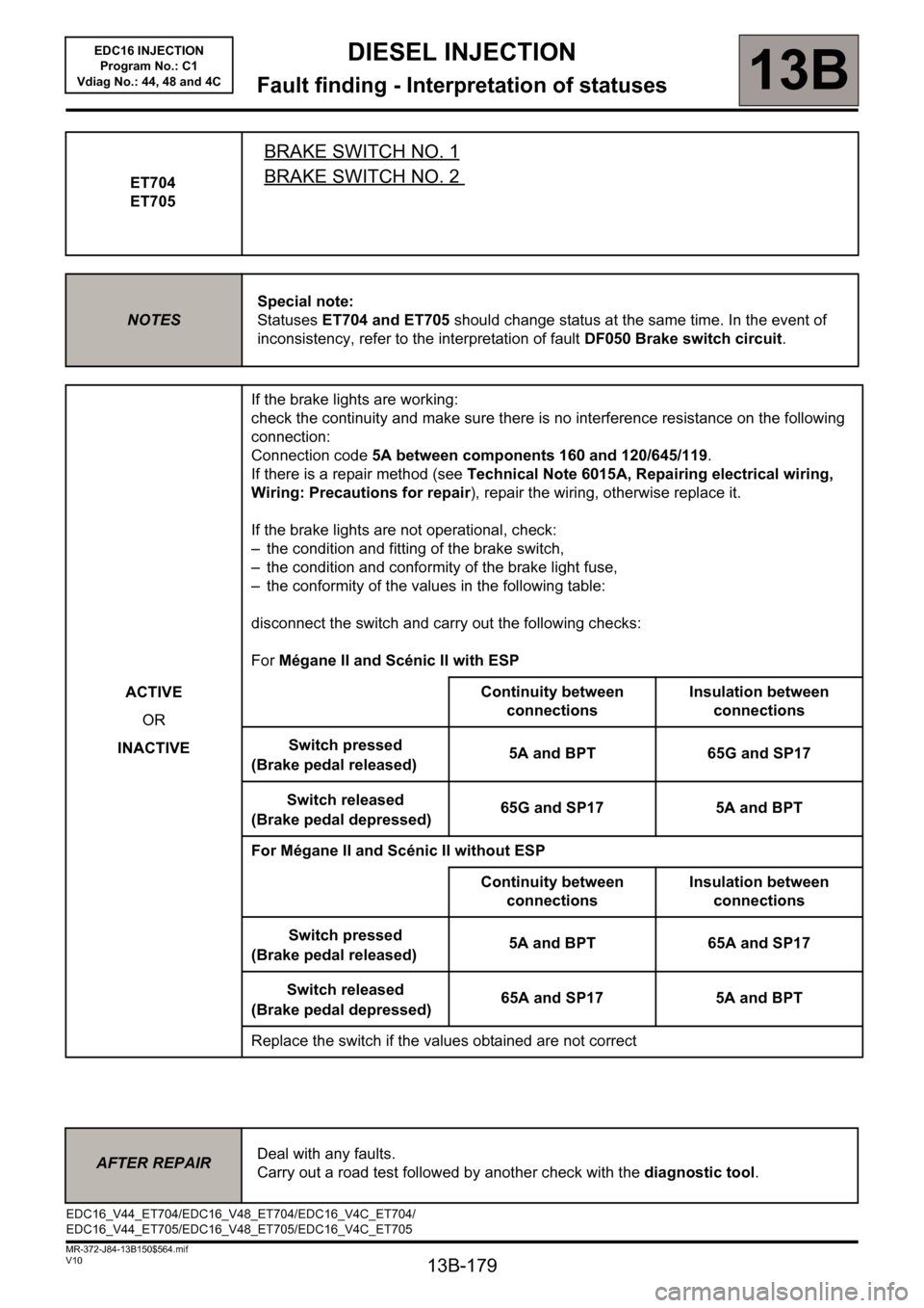
ET704
ET705
BRAKE SWITCH NO. 1
BRAKE SWITCH NO. 2
NOTESSpecial note:
Statuses ET704 and ET705 should change status at the same time. In the event of
inconsistency, refer to the interpretation of fault DF050 Brake switch circuit.
ACTIVE
OR
INACTIVEIf the brake lights are working:
check the continuity and make sure there is no interference resistance on the following
connection:
Connection code 5A between components 160 and 120/645/119.
If there is a repair method (see Technical Note 6015A, Repairing electrical wiring,
Wiring: Precautions for repair), repair the wiring, otherwise replace it.
If the brake lights are not operational, check:
– the condition and fitting of the brake switch,
– the condition and conformity of the brake light fuse,
– the conformity of the values in the following table:
disconnect the switch and carry out the following checks:
For Mégane II and Scénic II with ESP
Continuity between
connectionsInsulation between
connections
Switch pressed
(Brake pedal released)5A and BPT 65G and SP17
Switch released
(Brake pedal depressed)65G and SP17 5A and BPT
For Mégane II and Scénic II without ESP
Continuity between
connectionsInsulation between
connections
Switch pressed
(Brake pedal released)5A and BPT 65A and SP17
Switch released
(Brake pedal depressed)65A and SP17 5A and BPT
Replace the switch if the values obtained are not correct