ESP RENAULT SCENIC 2011 J95 / 3.G Engine And Peripherals EDC16 Workshop Manual
[x] Cancel search | Manufacturer: RENAULT, Model Year: 2011, Model line: SCENIC, Model: RENAULT SCENIC 2011 J95 / 3.GPages: 365, PDF Size: 2.11 MB
Page 283 of 365
13B-283
MR-372-J84-13B200$684.mif
V13
DIESEL INJECTION
Fault finding – Interpretation of parameters
EDC16
Program No: C1
Vdiag No: 18, 1C, 20,
50, 58, 5C
13B
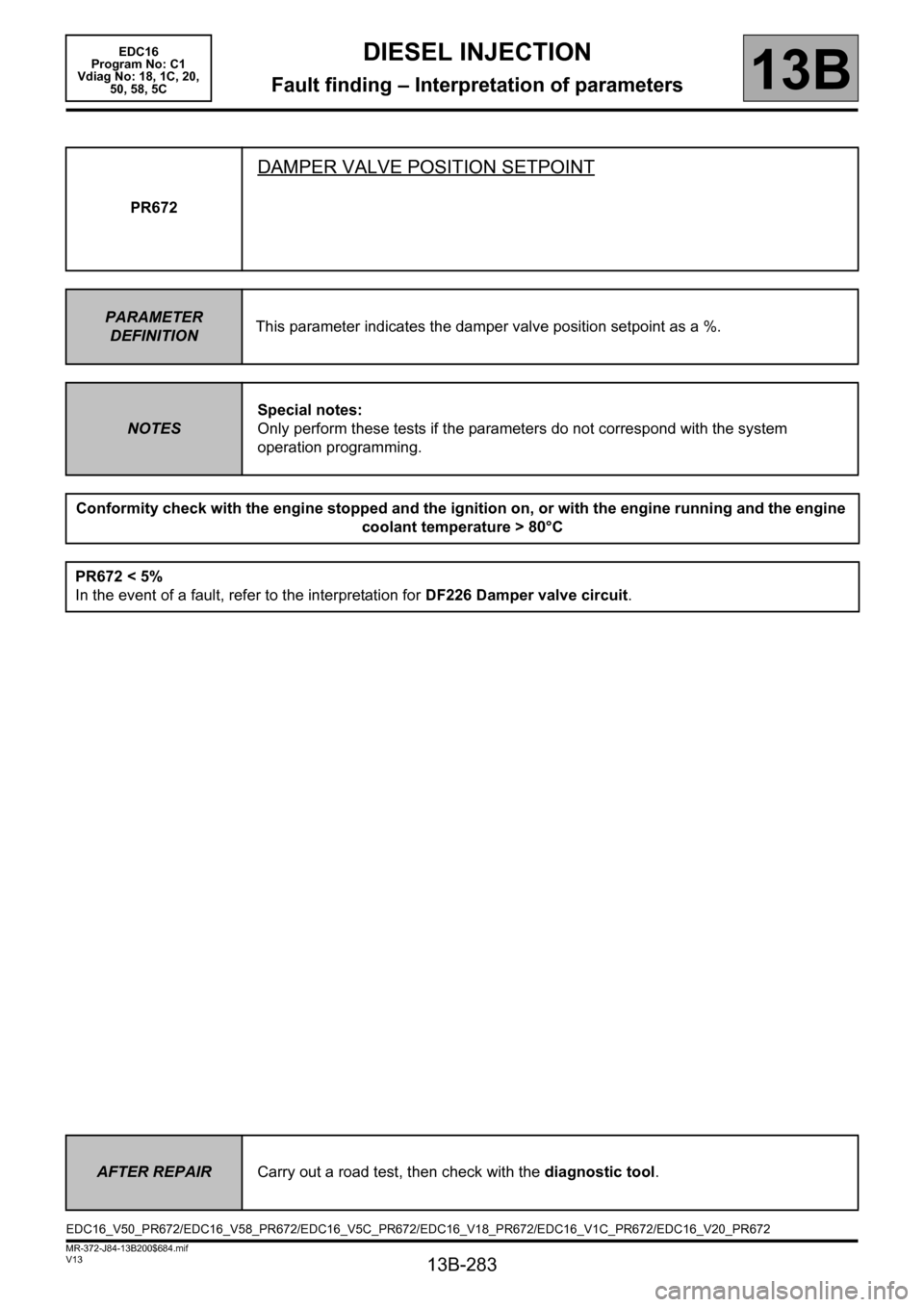
PR672
DAMPER VALVE POSITION SETPOINT
PARAMETER
DEFINITIONThis parameter indicates the damper valve position setpoint as a %.
NOTESSpecial notes:
Only perform these tests if the parameters do not correspond with the system
operation programming.
Conformity check with the engine stopped and the ignition on, or with the engine running and the engine
coolant temperature > 80°C
PR672 < 5%
In the event of a fault, refer to the interpretation for DF226 Damper valve circuit.
AFTER REPAIRCarry out a road test, then check with the diagnostic tool.
EDC16_V50_PR672/EDC16_V58_PR672/EDC16_V5C_PR672/EDC16_V18_PR672/EDC16_V1C_PR672/EDC16_V20_PR672
Page 293 of 365
13B-293
MR-372-J84-13B200$756.mif
V13
DIESEL INJECTION
Fault finding – Interpretation of commands
EDC16
Program No: C1
Vdiag No: 18, 1C, 20,
50, 58, 5C
13B
SC002
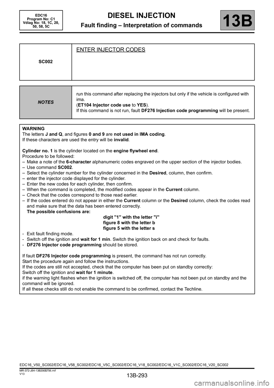
ENTER INJECTOR CODES
NOTESrun this command after replacing the injectors but only if the vehicle is configured with
ima.
(ET104 Injector code use to YES).
If this command is not run, fault DF276 Injection code programming will be present.
WARNING
The letters J and Q, and figures 0 and 9 are not used in IMA coding.
If these characters are used the entry will be invalid.
Cylinder no. 1 is the cylinder located on the engine flywheel end.
Procedure to be followed:
– Make a note of the 6-character alphanumeric codes engraved on the upper section of the injector bodies.
– Use command SC002.
– Select the cylinder number for the cylinder concerned in the Desired, column, then confirm.
– enter the injector code displayed for the cylinder.
– Enter the new codes for each cylinder, then confirm.
– When the command is completed, the modified codes appear in the Current column.
– Check that the codes correspond to those read earlier.
– If the codes entered do not appear in either the Current column or the Desired column, check the codes read
and make sure that the data has been entered correctly.
The possible confusions are:
digit "1" with the letter "i"
figure 8 with the letter b
figure 5 with the letter s
- Exit fault finding mode.
- Switch off the ignition and wait for 1 min. Switch the ignition back on and check for faults.
-DF276 Injector code programming should be stored.
If fault DF276 Injector code programming is present, the command has not run correctly.
Start the procedure again and follow the instructions.
If the codes are still not accepted, check that the computer has been put on standby correctly:
Switch off the ignition and wait for 1 minute.
if the warning light flashes when the ignition is switched off, the computer has not been put on standby and the
command will be ignored.
If all these checks still do not enable the command to be confirmed, contact the Techline.
EDC16_V50_SC002/EDC16_V58_SC002/EDC16_V5C_SC002/EDC16_V18_SC002/EDC16_V1C_SC002/EDC16_V20_SC002
Page 294 of 365
13B-294
MR-372-J84-13B200$756.mif
V13
DIESEL INJECTION
Fault finding – Interpretation of commands
EDC16
Program No: C1
Vdiag No: 18, 1C, 20,
50, 58, 5C
13B
SC003
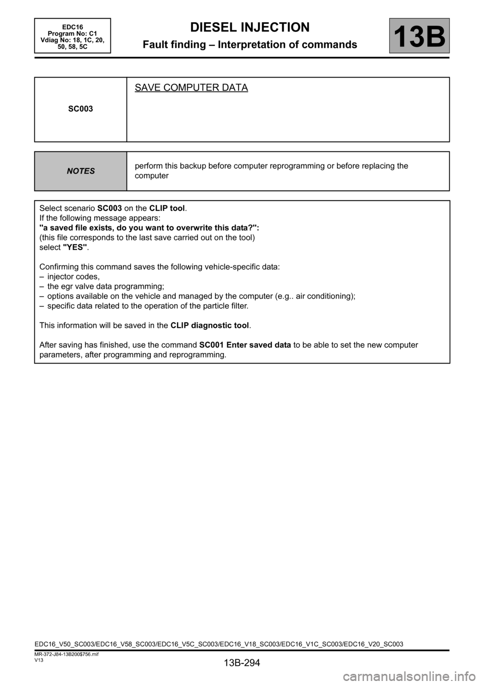
SAVE COMPUTER DATA
NOTESperform this backup before computer reprogramming or before replacing the
computer
Select scenario SC003 on the CLIP tool.
If the following message appears:
"a saved file exists, do you want to overwrite this data?":
(this file corresponds to the last save carried out on the tool)
select "YES".
Confirming this command saves the following vehicle-specific data:
– injector codes,
– the egr valve data programming;
– options available on the vehicle and managed by the computer (e.g.. air conditioning);
– specific data related to the operation of the particle filter.
This information will be saved in the CLIP diagnostic tool.
After saving has finished, use the command SC001 Enter saved data to be able to set the new computer
parameters, after programming and reprogramming.
EDC16_V50_SC003/EDC16_V58_SC003/EDC16_V5C_SC003/EDC16_V18_SC003/EDC16_V1C_SC003/EDC16_V20_SC003
Page 317 of 365
13B-317
MR-372-J84-13B200$792.mif
V13
13B
DIESEL INJECTION
Fault finding – Customer complaints
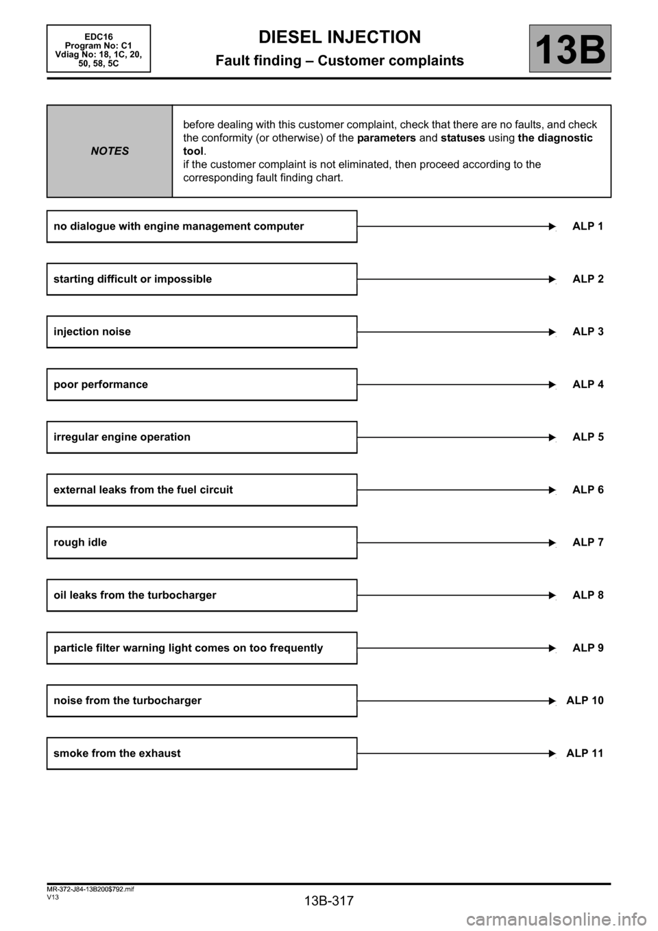
NOTESbefore dealing with this customer complaint, check that there are no faults, and check
the conformity (or otherwise) of the parameters and statuses using the diagnostic
tool.
if the customer complaint is not eliminated, then proceed according to the
corresponding fault finding chart.
no dialogue with engine management computer ALP 1
starting difficult or impossibleALP 2
injection noiseALP 3
poor performanceALP 4
irregular engine operationALP 5
external leaks from the fuel circuit ALP 6
rough idleALP 7
oil leaks from the turbochargerALP 8
particle filter warning light comes on too frequently ALP 9
noise from the turbochargerALP 10
smoke from the exhaustALP 11
EDC16
Program No: C1
Vdiag No: 18, 1C, 20,
50, 58, 5C
MR-372-J84-13B200$792.mif
Page 318 of 365
13B-318
MR-372-J84-13B200$828.mif
V13
13B
DIESEL INJECTION
Fault finding – Fault Finding Chart
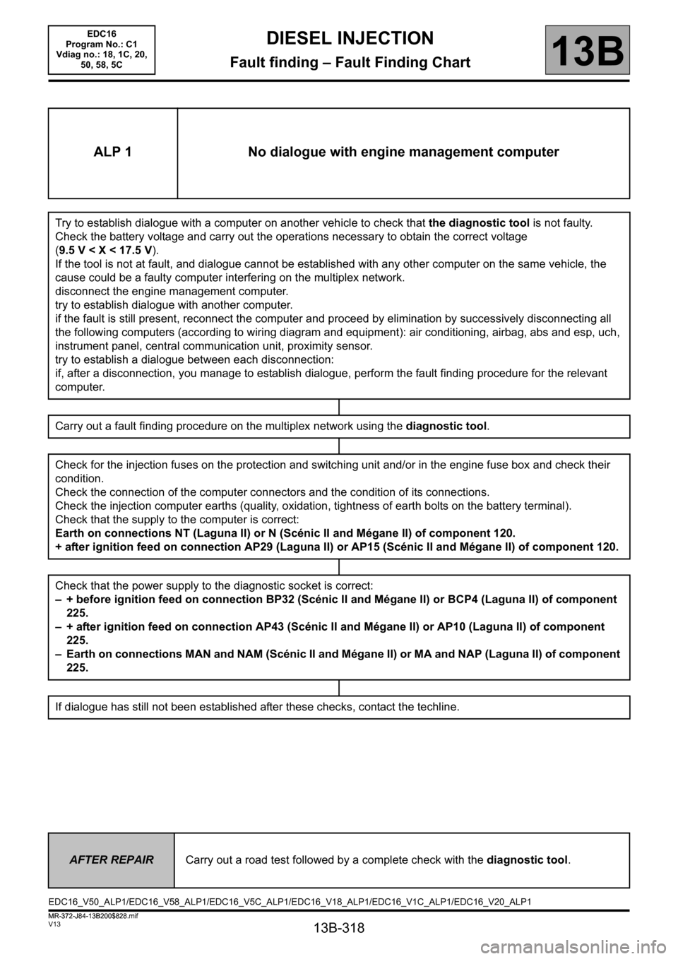
ALP 1 No dialogue with engine management computer
Try to establish dialogue with a computer on another vehicle to check that the diagnostic tool is not faulty.
Check the battery voltage and carry out the operations necessary to obtain the correct voltage
(9.5V
cause could be a faulty computer interfering on the multiplex network.
disconnect the engine management computer.
try to establish dialogue with another computer.
if the fault is still present, reconnect the computer and proceed by elimination by successively disconnecting all
the following computers (according to wiring diagram and equipment): air conditioning, airbag, abs and esp, uch,
instrument panel, central communication unit, proximity sensor.
try to establish a dialogue between each disconnection:
if, after a disconnection, you manage to establish dialogue, perform the fault finding procedure for the relevant
computer.
Carry out a fault finding procedure on the multiplex network using the diagnostic tool.
Check for the injection fuses on the protection and switching unit and/or in the engine fuse box and check their
condition.
Check the connection of the computer connectors and the condition of its connections.
Check the injection computer earths (quality, oxidation, tightness of earth bolts on the battery terminal).
Check that the supply to the computer is correct:
Earth on connections NT (Laguna II) or N (Scénic II and Mégane II) of component 120.
+ after ignition feed on connection AP29 (Laguna II) or AP15 (Scénic II and Mégane II) of component 120.
Check that the power supply to the diagnostic socket is correct:
– + before ignition feed on connection BP32 (Scénic II and Mégane II) or BCP4 (Laguna II) of component
225.
– + after ignition feed on connection AP43 (Scénic II and Mégane II) or AP10 (Laguna II) of component
225.
– Earth on connections MAN and NAM (Scénic II and Mégane II) or MA and NAP (Laguna II) of component
225.
If dialogue has still not been established after these checks, contact the techline.
AFTER REPAIRCarry out a road test followed by a complete check with the diagnostic tool.
EDC16_V50_ALP1/EDC16_V58_ALP1/EDC16_V5C_ALP1/EDC16_V18_ALP1/EDC16_V1C_ALP1/EDC16_V20_ALP1 EDC16
Program No.: C1
Vdiag no.: 18, 1C, 20,
50, 58, 5C
MR-372-J84-13B200$828.mif
Page 328 of 365
13B-328
MR-372-J84-13B200$828.mif
V13
EDC16
Program No.: C1
Vdiag no.: 18, 1C, 20,
50, 58, 5CDIESEL INJECTION
Fault finding – Fault Finding Chart13B
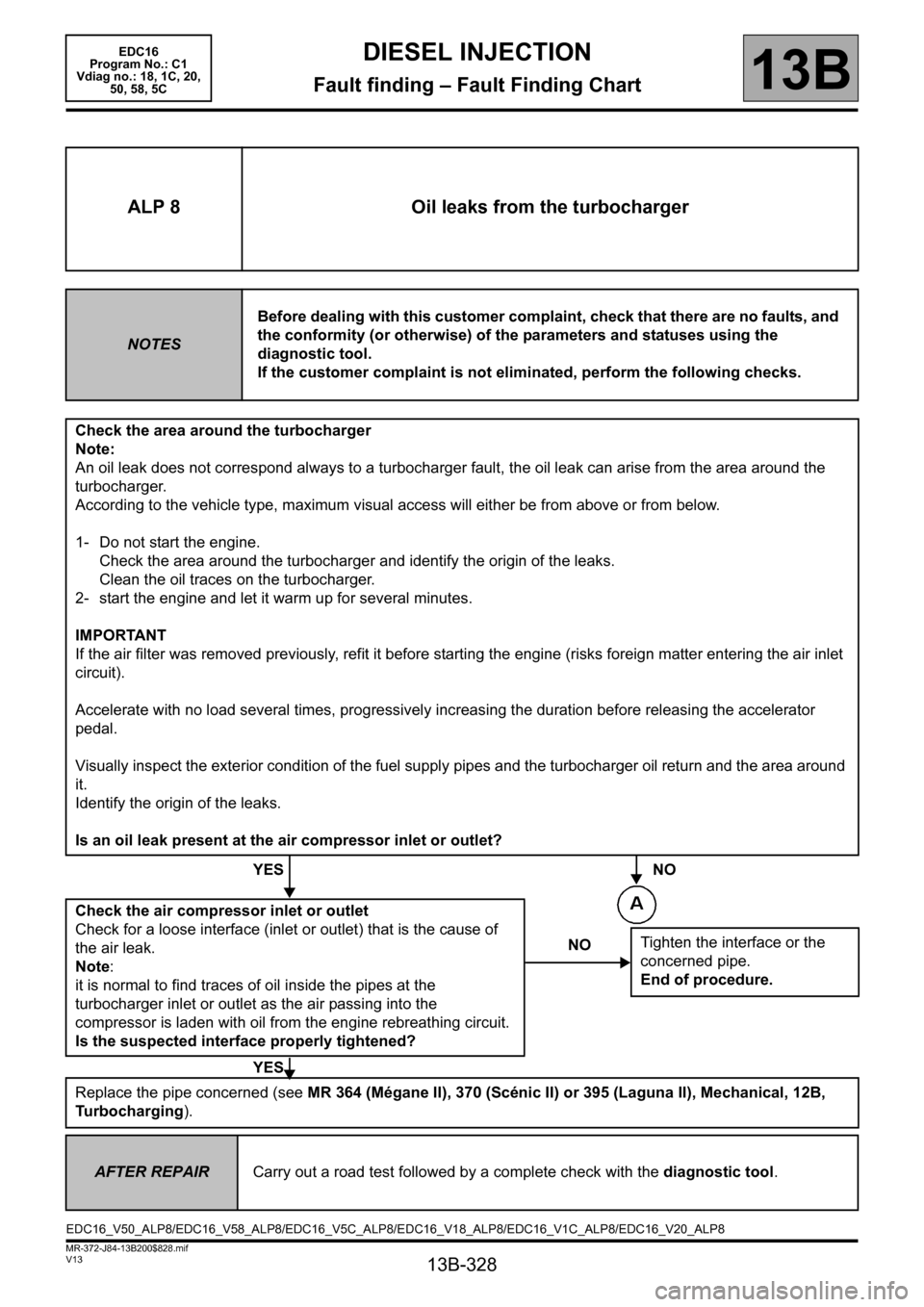
ALP 8 Oil leaks from the turbocharger
NOTESBefore dealing with this customer complaint, check that there are no faults, and
the conformity (or otherwise) of the parameters and statuses using the
diagnostic tool.
If the customer complaint is not eliminated, perform the following checks.
Check the area around the turbocharger
Note:
An oil leak does not correspond always to a turbocharger fault, the oil leak can arise from the area around the
turbocharger.
According to the vehicle type, maximum visual access will either be from above or from below.
1- Do not start the engine.
Check the area around the turbocharger and identify the origin of the leaks.
Clean the oil traces on the turbocharger.
2- start the engine and let it warm up for several minutes.
IMPORTANT
If the air filter was removed previously, refit it before starting the engine (risks foreign matter entering the air inlet
circuit).
Accelerate with no load several times, progressively increasing the duration before releasing the accelerator
pedal.
Visually inspect the exterior condition of the fuel supply pipes and the turbocharger oil return and the area around
it.
Identify the origin of the leaks.
Is an oil leak present at the air compressor inlet or outlet?
YES NO
Check the air compressor inlet or outlet
Check for a loose interface (inlet or outlet) that is the cause of
the air leak.
Note:
it is normal to find traces of oil inside the pipes at the
turbocharger inlet or outlet as the air passing into the
compressor is laden with oil from the engine rebreathing circuit.
Is the suspected interface properly tightened?
YES
Replace the pipe concerned (see MR 364 (Mégane II), 370 (Scénic II) or 395 (Laguna II), Mechanical, 12B,
Turbocharging).
NOTighten the interface or the
concerned pipe.
End of procedure.
AFTER REPAIRCarry out a road test followed by a complete check with the diagnostic tool.
EDC16_V50_ALP8/EDC16_V58_ALP8/EDC16_V5C_ALP8/EDC16_V18_ALP8/EDC16_V1C_ALP8/EDC16_V20_ALP8
Page 332 of 365
13B-332
MR-372-J84-13B200$828.mif
V13
EDC16
Program No.: C1
Vdiag no.: 18, 1C, 20,
50, 58, 5CDIESEL INJECTION
Fault finding – Fault Finding Chart13B
ALP 9
CONTINUED 1
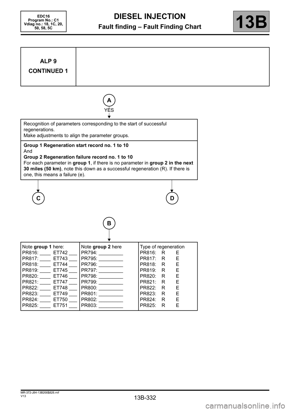
Recognition of parameters corresponding to the start of successful
regenerations.
Make adjustments to align the parameter groups.
Group 1 Regeneration start record no. 1 to 10
And
Group 2 Regeneration failure record no. 1 to 10
For each parameter in group 1, if there is no parameter in group 2 in the next
30 miles (50 km), note this down as a successful regeneration (R). If there is
one, this means a failure (e).
Note group 1 here:
PR816: ____ ET742 ___
PR817: ____ ET743 ___
PR818: ____ ET744 ___
PR819: ____ ET745 ___
PR820: ____ ET746 ___
PR821: ____ ET747 ___
PR822: ____ ET748 ___
PR823: ____ ET749 ___
PR824: ____ ET750 ___
PR825: ____ ET751 ___Note group 2 here
PR794: _________
PR795: _________
PR796: _________
PR797: _________
PR798: _________
PR799: _________
PR800: _________
PR801: _________
PR802: _________
PR803: _________Type of regeneration
PR816: R E
PR817: R E
PR818: R E
PR819: R E
PR820: R E
PR821: R E
PR822: R E
PR823: R E
PR824: R E
PR825: R E
A
YES
CD
B
Page 337 of 365
13B-337
MR-372-J84-13B200$828.mif
V13
EDC16
Program No.: C1
Vdiag no.: 18, 1C, 20,
50, 58, 5CDIESEL INJECTION
Fault finding – Fault Finding Chart13B
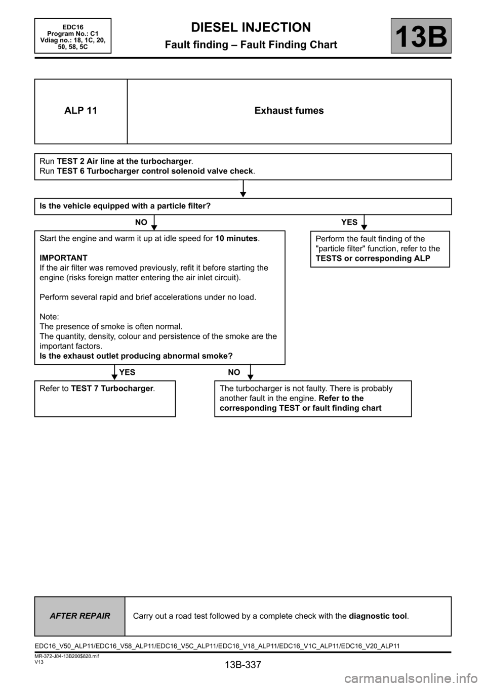
ALP 11 Exhaust fumes
Run TEST 2 Air line at the turbocharger.
Run TEST 6 Turbocharger control solenoid valve check.
Is the vehicle equipped with a particle filter?
NO YES
Start the engine and warm it up at idle speed for 10 minutes.
IMPORTANT
If the air filter was removed previously, refit it before starting the
engine (risks foreign matter entering the air inlet circuit).
Perform several rapid and brief accelerations under no load.
Note:
The presence of smoke is often normal.
The quantity, density, colour and persistence of the smoke are the
important factors.
Is the exhaust outlet producing abnormal smoke?
YES NO
Refer to TEST 7 Turbocharger. The turbocharger is not faulty. There is probably
another fault in the engine. Refer to the
corresponding TEST or fault finding chart
Perform the fault finding of the
"particle filter" function, refer to the
TESTS or corresponding ALP
AFTER REPAIRCarry out a road test followed by a complete check with the diagnostic tool.
EDC16_V50_ALP11/EDC16_V58_ALP11/EDC16_V5C_ALP11/EDC16_V18_ALP11/EDC16_V1C_ALP11/EDC16_V20_ALP11