OBD port RENAULT SCENIC 2011 J95 / 3.G Engine And Peripherals EDC16 Workshop Manual
[x] Cancel search | Manufacturer: RENAULT, Model Year: 2011, Model line: SCENIC, Model: RENAULT SCENIC 2011 J95 / 3.GPages: 365, PDF Size: 2.11 MB
Page 17 of 365
13B-17
MR-372-J84-13B200$108.mif
V13
DIESEL INJECTION
Fault finding – System operation
EDC16
Program No: C1
Vdiag No: 18, 1C, 20,
50, 58, 5C
13B
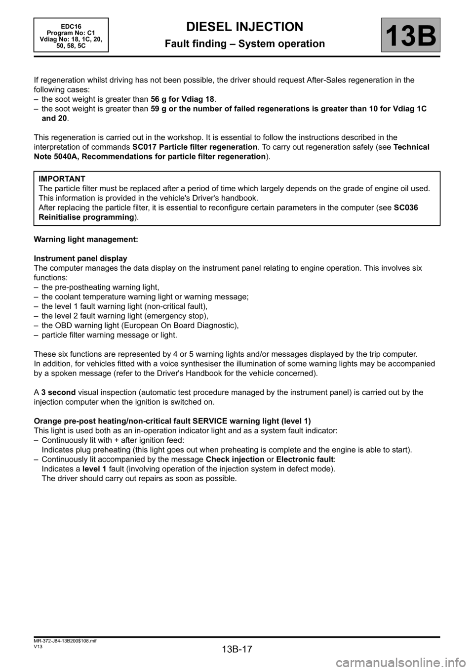
If regeneration whilst driving has not been possible, the driver should request After-Sales regeneration in the
following cases:
– the soot weight is greater than 56 g for Vdiag 18.
– the soot weight is greater than 59 g or the number of failed regenerations is greater than 10 for Vdiag 1C
and 20.
This regeneration is carried out in the workshop. It is essential to follow the instructions described in the
interpretation of commands SC017 Particle filter regeneration. To carry out regeneration safely (see Te c h n i c a l
Note 5040A, Recommendations for particle filter regeneration).
Warning light management:
Instrument panel display
The computer manages the data display on the instrument panel relating to engine operation. This involves six
functions:
– the pre-postheating warning light,
– the coolant temperature warning light or warning message;
– the level 1 fault warning light (non-critical fault),
– the level 2 fault warning light (emergency stop),
– the OBD warning light (European On Board Diagnostic),
– particle filter warning message or light.
These six functions are represented by 4 or 5 warning lights and/or messages displayed by the trip computer.
In addition, for vehicles fitted with a voice synthesiser the illumination of some warning lights may be accompanied
by a spoken message (refer to the Driver's Handbook for the vehicle concerned).
A 3 second visual inspection (automatic test procedure managed by the instrument panel) is carried out by the
injection computer when the ignition is switched on.
Orange pre-post heating/non-critical fault SERVICE warning light (level 1)
This light is used both as an in-operation indicator light and as a system fault indicator:
– Continuously lit with + after ignition feed:
Indicates plug preheating (this light goes out when preheating is complete and the engine is able to start).
– Continuously lit accompanied by the message Check injection or Electronic fault:
Indicates a level 1 fault (involving operation of the injection system in defect mode).
The driver should carry out repairs as soon as possible. IMPORTANT
The particle filter must be replaced after a period of time which largely depends on the grade of engine oil used.
This information is provided in the vehicle's Driver's handbook.
After replacing the particle filter, it is essential to reconfigure certain parameters in the computer (see SC036
Reinitialise programming).
Page 68 of 365
13B-68
MR-372-J84-13B200$288.mif
V13
DIESEL INJECTION
Fault finding – Interpretation of faults
EDC16
Program No.: C1
Vdiag no.: 18, 1C, 20,
50, 58, 5C
13B
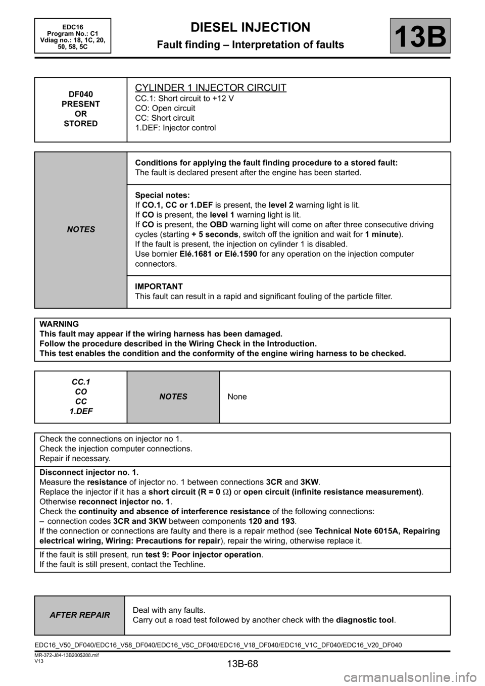
DF040
PRESENT
OR
STOREDCYLINDER 1 INJECTOR CIRCUIT
CC.1: Short circuit to +12 V
CO: Open circuit
CC: Short circuit
1.DEF: Injector control
NOTESConditions for applying the fault finding procedure to a stored fault:
The fault is declared present after the engine has been started.
Special notes:
If CO.1, CC or 1.DEF is present, the level 2 warning light is lit.
If CO is present, the level 1 warning light is lit.
If CO is present, the OBD warning light will come on after three consecutive driving
cycles (starting + 5 seconds, switch off the ignition and wait for 1 minute).
If the fault is present, the injection on cylinder 1 is disabled.
Use bornier Elé.1681 or Elé.1590 for any operation on the injection computer
connectors.
IMPORTANT
This fault can result in a rapid and significant fouling of the particle filter.
WARNING
This fault may appear if the wiring harness has been damaged.
Follow the procedure described in the Wiring Check in the Introduction.
This test enables the condition and the conformity of the engine wiring harness to be checked.
CC.1
CO
CC
1.DEF
NOTESNone
Check the connections on injector no 1.
Check the injection computer connections.
Repair if necessary.
Disconnect injector no. 1.
Measure the resistance of injector no. 1 between connections 3CR and 3KW.
Replace the injector if it has a short circuit (R = 0 Ω) or open circuit (infinite resistance measurement).
Otherwise reconnect injector no. 1.
Check the continuity and absence of interference resistance of the following connections:
– connection codes 3CR and 3KW between components 120 and 193.
If the connection or connections are faulty and there is a repair method (see Technical Note 6015A, Repairing
electrical wiring, Wiring: Precautions for repair), repair the wiring, otherwise replace it.
If the fault is still present, run test 9: Poor injector operation.
If the fault is still present, contact the Techline.
AFTER REPAIRDeal with any faults.
Carry out a road test followed by another check with the diagnostic tool.
EDC16_V50_DF040/EDC16_V58_DF040/EDC16_V5C_DF040/EDC16_V18_DF040/EDC16_V1C_DF040/EDC16_V20_DF040
Page 69 of 365
13B-69
MR-372-J84-13B200$288.mif
V13
DIESEL INJECTION
Fault finding – Interpretation of faults
EDC16
Program No.: C1
Vdiag no.: 18, 1C, 20,
50, 58, 5C
13B
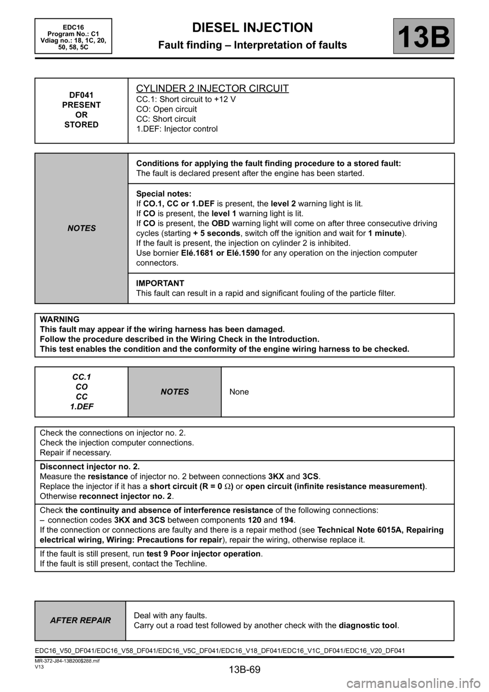
DF041
PRESENT
OR
STOREDCYLINDER 2 INJECTOR CIRCUIT
CC.1: Short circuit to +12 V
CO: Open circuit
CC: Short circuit
1.DEF: Injector control
NOTESConditions for applying the fault finding procedure to a stored fault:
The fault is declared present after the engine has been started.
Special notes:
If CO.1, CC or 1.DEF is present, the level 2 warning light is lit.
If CO is present, the level 1 warning light is lit.
If CO is present, the OBD warning light will come on after three consecutive driving
cycles (starting + 5 seconds, switch off the ignition and wait for 1 minute).
If the fault is present, the injection on cylinder 2 is inhibited.
Use bornier Elé.1681 or Elé.1590 for any operation on the injection computer
connectors.
IMPORTANT
This fault can result in a rapid and significant fouling of the particle filter.
WARNING
This fault may appear if the wiring harness has been damaged.
Follow the procedure described in the Wiring Check in the Introduction.
This test enables the condition and the conformity of the engine wiring harness to be checked.
CC.1
CO
CC
1.DEF
NOTESNone
Check the connections on injector no. 2.
Check the injection computer connections.
Repair if necessary.
Disconnect injector no. 2.
Measure the resistance of injector no. 2 between connections 3KX and 3CS.
Replace the injector if it has a short circuit (R = 0 Ω) or open circuit (infinite resistance measurement).
Otherwise reconnect injector no. 2.
Check the continuity and absence of interference resistance of the following connections:
– connection codes 3KX and 3CS between components 120 and 194.
If the connection or connections are faulty and there is a repair method (see Technical Note 6015A, Repairing
electrical wiring, Wiring: Precautions for repair), repair the wiring, otherwise replace it.
If the fault is still present, run test 9 Poor injector operation.
If the fault is still present, contact the Techline.
AFTER REPAIRDeal with any faults.
Carry out a road test followed by another check with the diagnostic tool.
EDC16_V50_DF041/EDC16_V58_DF041/EDC16_V5C_DF041/EDC16_V18_DF041/EDC16_V1C_DF041/EDC16_V20_DF041
Page 70 of 365
13B-70
MR-372-J84-13B200$288.mif
V13
DIESEL INJECTION
Fault finding – Interpretation of faults
EDC16
Program No.: C1
Vdiag no.: 18, 1C, 20,
50, 58, 5C
13B
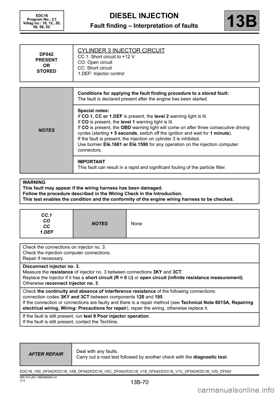
DF042
PRESENT
OR
STOREDCYLINDER 3 INJECTOR CIRCUIT
CC.1: Short circuit to +12 V
CO: Open circuit
CC: Short circuit
1.DEF: Injector control
NOTESConditions for applying the fault finding procedure to a stored fault:
The fault is declared present after the engine has been started.
Special notes:
If CO.1, CC or 1.DEF is present, the level 2 warning light is lit.
If CO is present, the level 1 warning light is lit.
If CO is present, the OBD warning light will come on after three consecutive driving
cycles (starting + 5 seconds, switch off the ignition and wait for 1 minute).
If the fault is present, the injection on cylinder 3 is inhibited.
Use bornier Elé.1681 or Elé.1590 for any operation on the injection computer
connectors.
IMPORTANT
This fault can result in a rapid and significant fouling of the particle filter.
WARNING
This fault may appear if the wiring harness has been damaged.
Follow the procedure described in the Wiring Check in the Introduction.
This test enables the condition and the conformity of the engine wiring harness to be checked.
CC.1
CO
CC
1.DEF
NOTESNone
Check the connections on injector no. 3.
Check the injection computer connections.
Repair if necessary.
Disconnect injector no. 3.
Measure the resistance of injector no. 3 between connections 3KY and 3CT.
Replace the injector if it has a short circuit (R = 0 Ω) or open circuit (infinite resistance measurement).
Otherwise reconnect injector no. 3.
Check the continuity and absence of interference resistance of the following connections:
connection codes 3KY and 3CT between components 120 and 195.
If the connection or connections are faulty and there is a repair method (see Technical Note 6015A, Repairing
electrical wiring, Wiring: Precautions for repair), repair the wiring, otherwise replace it.
If the fault is still present, run test 9 Poor injector operation.
If the fault is still present, contact the Techline.
AFTER REPAIRDeal with any faults.
Carry out a road test followed by another check with the diagnostic tool.
EDC16_V50_DF042/EDC16_V58_DF042/EDC16_V5C_DF042/EDC16_V18_DF042/EDC16_V1C_DF042/EDC16_V20_DF042
Page 71 of 365
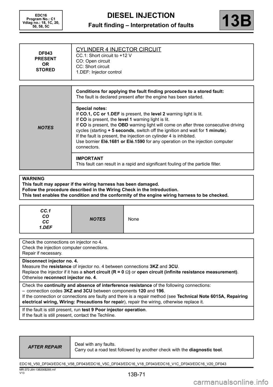
13B-71
MR-372-J84-13B200$288.mif
V13
DIESEL INJECTION
Fault finding – Interpretation of faults
EDC16
Program No.: C1
Vdiag no.: 18, 1C, 20,
50, 58, 5C
13B
DF043
PRESENT
OR
STOREDCYLINDER 4 INJECTOR CIRCUIT
CC.1: Short circuit to +12 V
CO: Open circuit
CC: Short circuit
1.DEF: Injector control
NOTESConditions for applying the fault finding procedure to a stored fault:
The fault is declared present after the engine has been started.
Special notes:
If CO.1, CC or 1.DEF is present, the level 2 warning light is lit.
If CO is present, the level 1 warning light is lit.
If CO is present, the OBD warning light will come on after three consecutive driving
cycles (starting + 5 seconds, switch off the ignition and wait for 1 minute).
If the fault is present, the injection on cylinder 4 is inhibited.
Use bornier Elé.1681 or Elé.1590 for any operation on the injection computer
connectors.
IMPORTANT
This fault can result in a rapid and significant fouling of the particle filter.
WARNING
This fault may appear if the wiring harness has been damaged.
Follow the procedure described in the Wiring Check in the Introduction.
This test enables the condition and the conformity of the engine wiring harness to be checked.
CC.1
CO
CC
1.DEF
NOTESNone
Check the connections on injector no 4.
Check the injection computer connections.
Repair if necessary.
Disconnect injector no. 4.
Measure the resistance of injector no. 4 between connections 3KZ and 3CU.
Replace the injector if it has a short circuit (R = 0 Ω) or open circuit (infinite resistance measurement).
Otherwise reconnect injector no. 4.
Check the continuity and absence of interference resistance of the following connections:
– connection codes 3KZ and 3CU between components 120 and 196.
If the connection or connections are faulty and there is a repair method (see Technical Note 6015A, Repairing
electrical wiring, Wiring: Precautions for repair), repair the wiring, otherwise replace it.
If the fault is still present, run test 9 Poor injector operation.
If the fault is still present, contact the Techline.
AFTER REPAIRDeal with any faults.
Carry out a road test followed by another check with the diagnostic tool.
EDC16_V50_DF043/EDC16_V58_DF043/EDC16_V5C_DF043/EDC16_V18_DF043/EDC16_V1C_DF043/EDC16_V20_DF043
Page 85 of 365
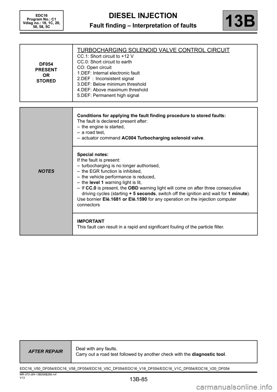
13B-85
MR-372-J84-13B200$288.mif
V13
DIESEL INJECTION
Fault finding – Interpretation of faults
EDC16
Program No.: C1
Vdiag no.: 18, 1C, 20,
50, 58, 5C
13B
DF054
PRESENT
OR
STORED
TURBOCHARGING SOLENOID VALVE CONTROL CIRCUIT
CC.1: Short circuit to +12 V
CC.0: Short circuit to earth
CO: Open circuit
1.DEF: Internal electronic fault
2.DEF : Inconsistent signal
3.DEF: Below minimum threshold
4.DEF: Above maximum threshold
5.DEF: Permanent high signal
NOTESConditions for applying the fault finding procedure to stored faults:
The fault is declared present after:
– the engine is started,
– a road test,
– actuator command AC004 Turbocharging solenoid valve.
Special notes:
If the fault is present:
– turbocharging is no longer authorised,
– the EGR function is inhibited,
– the vehicle performance is reduced,
– the level 1 warning light is lit,
–If CC.0 is present, the OBD warning light will come on after three consecutive
driving cycles (starting + 5 seconds, switch off the ignition and wait for 1 minute).
Use bornier Elé.1681 or Elé.1590 for any operation on the injection computer
connectors
IMPORTANT
This fault can result in a rapid and significant fouling of the particle filter.
AFTER REPAIRDeal with any faults.
Carry out a road test followed by another check with the diagnostic tool.
EDC16_V50_DF054/EDC16_V58_DF054/EDC16_V5C_DF054/EDC16_V18_DF054/EDC16_V1C_DF054/EDC16_V20_DF054
Page 115 of 365

13B-115
MR-372-J84-13B200$324.mif
V13
DIESEL INJECTION
Fault finding – Interpretation of faults
EDC16
Program No.: C1
Vdiag no.: 18, 1C, 20,
50, 58, 5C
13B
DF209
PRESENT
OR
STOREDEGR POSITION SENSOR CIRCUIT
CO.0: Open circuit or short circuit to earth
CC.1: Short circuit to + 12 V
1.DEF: Micro-breaks
NOTESConditions for applying the fault finding procedure to stored faults:
The fault is declared present after the engine is started or following a road test.
Special notes:
If the fault is present:
– there is smoke coming from the exhaust,
– the EGR offset fault finding function is disabled,
– the OBD warning light illuminates after three consecutive driving cycles (starting
+ 5 seconds + switch off the ignition and wait 1 minute).
Use bornier Elé.1681 or Elé.1590 for any operation on the injection computer
connectors.
Priorities when dealing with a number of faults:
–DF012 Sensor supply voltage no. 2 if it is present or stored.
IMPORTANT
This fault can result in a rapid and significant fouling of the particle filter.
If dealing with this fault requires the EGR valve to be replaced, run command SC036
Reinitialise programming and select EGR valve to reinitialise the EGR valve offsets
(see Replacement of components).
WARNING
This fault may appear if the wiring harness has been damaged.
Follow the procedure described in the Wiring Check in the Introduction.
This check enables the condition and the conformity of the engine wiring harness to be checked.
CO.0
NOTESNone
Check the EGR valve connections.
Check the injection computer connections.
Repair if necessary.
Check the continuity and insulation to earth of the following connections:
– connection code 3EL,
– connection code 3GC.
between components 120 and 1460.
If the connection or connections are faulty and there is a repair method (see Technical Note 6015A, Repairing
electrical wiring, Wiring: Precautions for repair), repair the wiring, otherwise replace it.
AFTER REPAIRDeal with any faults.
Carry out a road test followed by another check with the diagnostic tool.
EDC16_V50_DF209/EDC16_V58_DF209/EDC16_V5C_DF209/EDC16_V18_DF209/EDC16_V1C_DF209/EDC16_V20_DF209
Page 136 of 365
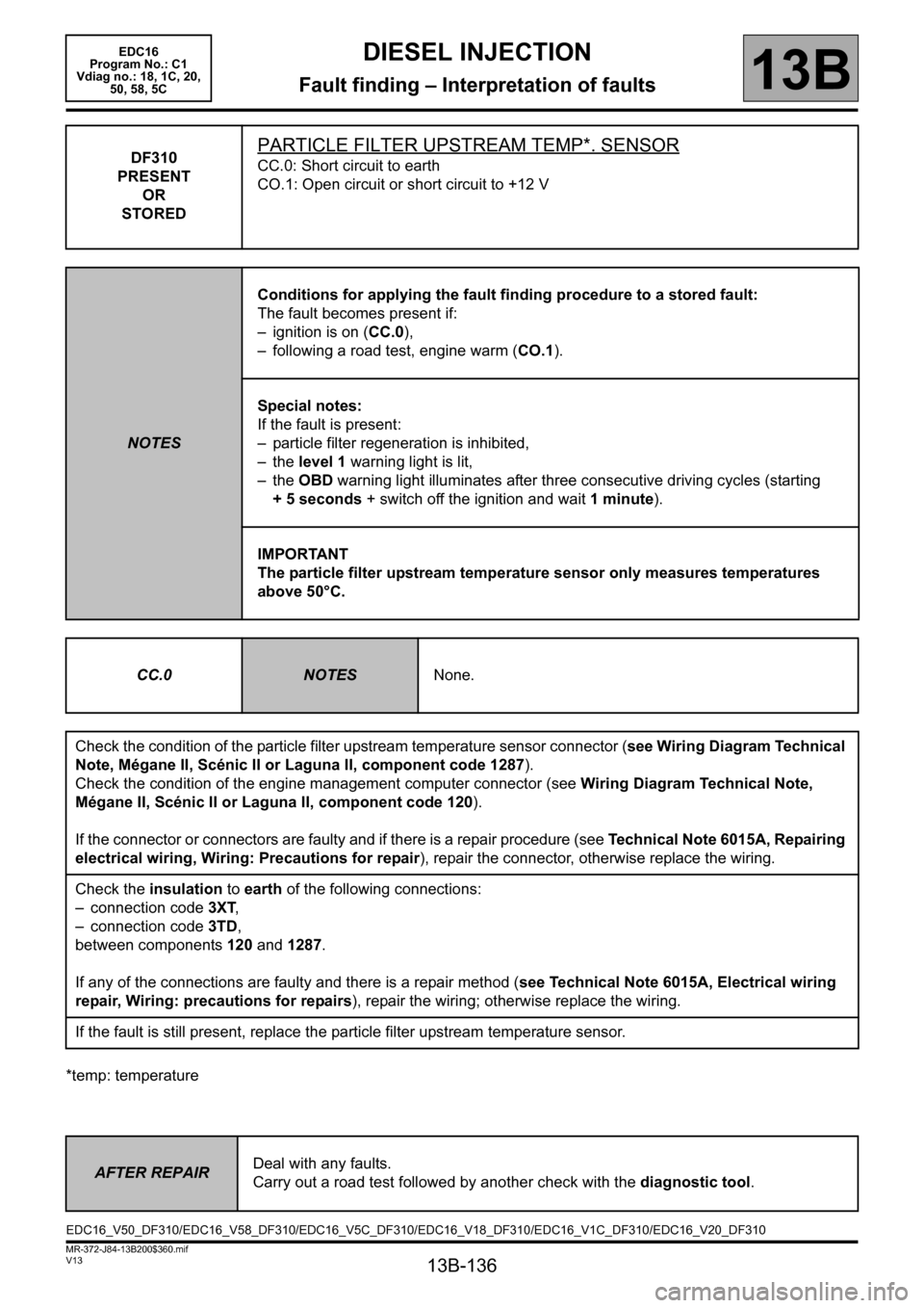
13B-136
MR-372-J84-13B200$360.mif
V13
DIESEL INJECTION
Fault finding – Interpretation of faults
EDC16
Program No.: C1
Vdiag no.: 18, 1C, 20,
50, 58, 5C
13B
*temp: temperatureDF310
PRESENT
OR
STORED
PARTICLE FILTER UPSTREAM TEMP*. SENSOR
CC.0: Short circuit to earth
CO.1: Open circuit or short circuit to +12 V
NOTESConditions for applying the fault finding procedure to a stored fault:
The fault becomes present if:
– ignition is on (CC.0),
– following a road test, engine warm (CO.1).
Special notes:
If the fault is present:
– particle filter regeneration is inhibited,
– the level 1 warning light is lit,
– the OBD warning light illuminates after three consecutive driving cycles (starting
+ 5 seconds + switch off the ignition and wait 1 minute).
IMPORTANT
The particle filter upstream temperature sensor only measures temperatures
above 50°C.
CC.0
NOTESNone.
Check the condition of the particle filter upstream temperature sensor connector (see Wiring Diagram Technical
Note, Mégane II, Scénic II or Laguna II, component code 1287).
Check the condition of the engine management computer connector (see Wiring Diagram Technical Note,
Mégane II, Scénic II or Laguna II, component code 120).
If the connector or connectors are faulty and if there is a repair procedure (see Technical Note 6015A, Repairing
electrical wiring, Wiring: Precautions for repair), repair the connector, otherwise replace the wiring.
Check the insulation to earth of the following connections:
– connection code3XT,
– connection code3TD,
between components 120 and 1287.
If any of the connections are faulty and there is a repair method (see Technical Note 6015A, Electrical wiring
repair, Wiring: precautions for repairs), repair the wiring; otherwise replace the wiring.
If the fault is still present, replace the particle filter upstream temperature sensor.
AFTER REPAIRDeal with any faults.
Carry out a road test followed by another check with the diagnostic tool.
EDC16_V50_DF310/EDC16_V58_DF310/EDC16_V5C_DF310/EDC16_V18_DF310/EDC16_V1C_DF310/EDC16_V20_DF310
Page 151 of 365
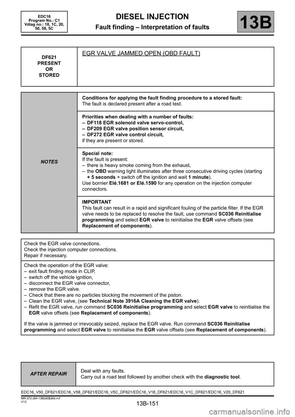
13B-151
MR-372-J84-13B200$360.mif
V13
DIESEL INJECTION
Fault finding – Interpretation of faults
EDC16
Program No.: C1
Vdiag no.: 18, 1C, 20,
50, 58, 5C
13B
DF621
PRESENT
OR
STOREDEGR VALVE JAMMED OPEN (OBD FAULT)
NOTESConditions for applying the fault finding procedure to a stored fault:
The fault is declared present after a road test.
Priorities when dealing with a number of faults:
– DF118 EGR solenoid valve servo-control,
– DF209 EGR valve position sensor circuit,
– DF272 EGR valve control circuit,
if they are present or stored.
Special note:
If the fault is present:
– there is heavy smoke coming from the exhaust,
– the OBD warning light illuminates after three consecutive driving cycles (starting
+ 5 seconds + switch off the ignition and wait 1 minute).
Use bornier Elé.1681 or Elé.1590 for any operation on the injection computer
connectors.
IMPORTANT
This fault can result in a rapid and significant fouling of the particle filter. If the EGR
valve needs to be replaced to resolve the fault, use command SC036 Reinitialise
programming and select EGR valve to reinitialise the EGR valve offsets (see
Replacement of components).
Check the EGR valve connections.
Check the injection computer connections.
Repair if necessary.
Check the operation of the EGR valve:
– exit fault finding mode in CLIP,
– switch off the vehicle ignition,
– disconnect the EGR valve connector,
– remove the EGR valve.
– Check that there are no particles blocking the movement of the piston.
– Clean the EGR valve, (see Technical Note 3916A Cleaning the EGR valve).
– Refit the EGR valve, run command SC036 Reinitialise programming and select EGR valve to reinitialise the
EGR valve offsets (see Replacement of components).
If the valve is jammed or irrevocably seized, replace the EGR valve. Run command SC036 Reinitialise
programming and select EGR valve to reinitialise the EGR valve offsets (see Replacement of components).
AFTER REPAIRDeal with any faults.
Carry out a road test followed by another check with the diagnostic tool.
EDC16_V50_DF621/EDC16_V58_DF621/EDC16_V5C_DF621/EDC16_V18_DF621/EDC16_V1C_DF621/EDC16_V20_DF621
Page 158 of 365
13B-158
MR-372-J84-13B200$360.mif
V13
DIESEL INJECTION
Fault finding – Interpretation of faults
EDC16
Program No.: C1
Vdiag no.: 18, 1C, 20,
50, 58, 5C
13B
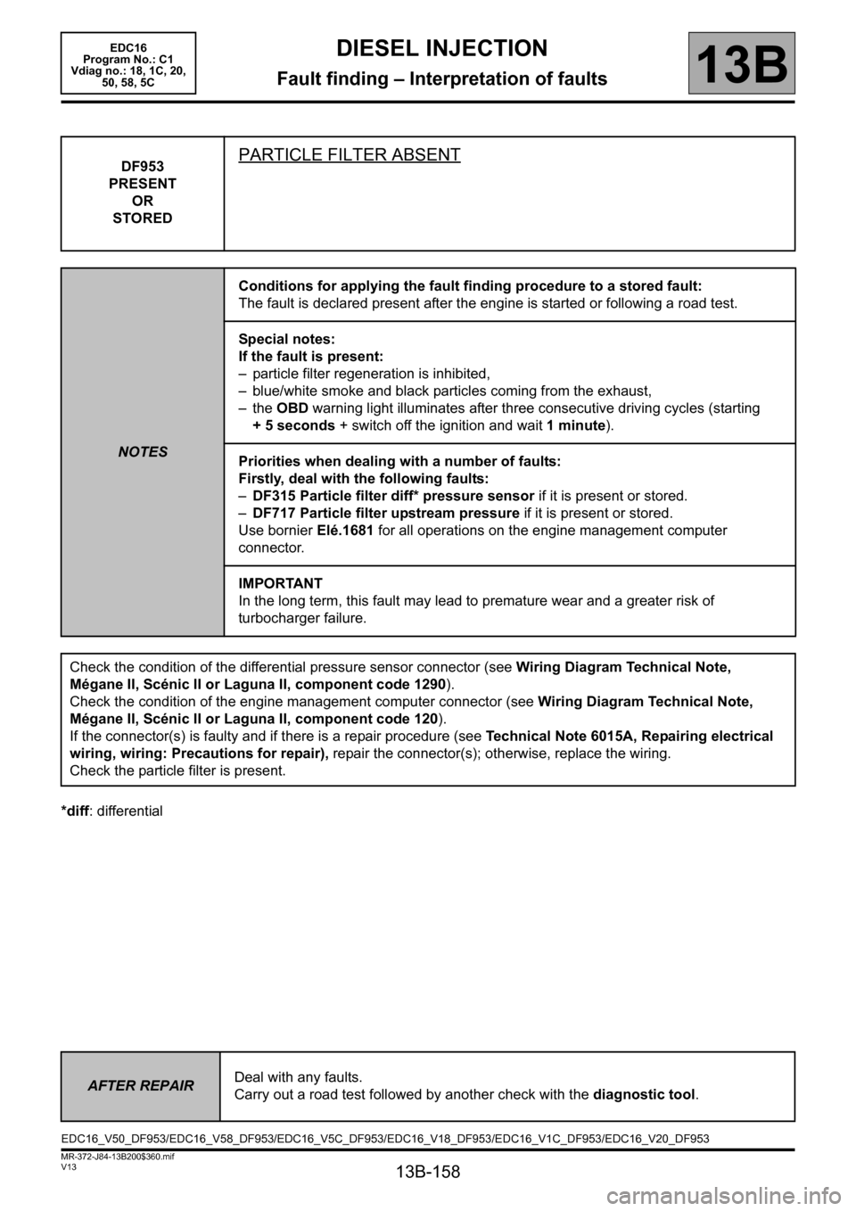
*diff: differentialDF953
PRESENT
OR
STORED
PARTICLE FILTER ABSENT
NOTESConditions for applying the fault finding procedure to a stored fault:
The fault is declared present after the engine is started or following a road test.
Special notes:
If the fault is present:
– particle filter regeneration is inhibited,
– blue/white smoke and black particles coming from the exhaust,
– the OBD warning light illuminates after three consecutive driving cycles (starting
+ 5 seconds + switch off the ignition and wait 1 minute).
Priorities when dealing with a number of faults:
Firstly, deal with the following faults:
–DF315 Particle filter diff* pressure sensor if it is present or stored.
–DF717 Particle filter upstream pressure if it is present or stored.
Use bornier Elé.1681 for all operations on the engine management computer
connector.
IMPORTANT
In the long term, this fault may lead to premature wear and a greater risk of
turbocharger failure.
Check the condition of the differential pressure sensor connector (see Wiring Diagram Technical Note,
Mégane II, Scénic II or Laguna II, component code 1290).
Check the condition of the engine management computer connector (see Wiring Diagram Technical Note,
Mégane II, Scénic II or Laguna II, component code 120).
If the connector(s) is faulty and if there is a repair procedure (see Technical Note 6015A, Repairing electrical
wiring, wiring: Precautions for repair), repair the connector(s); otherwise, replace the wiring.
Check the particle filter is present.
AFTER REPAIRDeal with any faults.
Carry out a road test followed by another check with the diagnostic tool.
EDC16_V50_DF953/EDC16_V58_DF953/EDC16_V5C_DF953/EDC16_V18_DF953/EDC16_V1C_DF953/EDC16_V20_DF953