test 9 RENAULT SCENIC 2011 J95 / 3.G Engine And Peripherals EDC16 Workshop Manual
[x] Cancel search | Manufacturer: RENAULT, Model Year: 2011, Model line: SCENIC, Model: RENAULT SCENIC 2011 J95 / 3.GPages: 365, PDF Size: 2.11 MB
Page 1 of 365
1Engine and peripherals
V13 MR-372-J84-13B200$TOC.mif
V13
13B
"The repair procedures given by the manufacturer in this document are based on the
technical specifications current when it was prepared.
The procedures may be modified as a result of changes introduced by the
manufacturer in the production of the various component units and accessories from
which his vehicles are constructed."
V13
All rights reserved by Renault s.a.s.
Edition Anglaise
Copying or translating, in part or in full, of this document or use of the service part
reference numbering system is forbidden without the prior written authority of
Renault s.a.s.
© Renault s.a.s. 2011
DIESEL INJECTION
EDC16
Program No.: C1
Vdiag no.: 18, 1C, 20, 50, 58, 5C
Fault finding – Introduction 13B - 2
Fault finding – Cleanliness guidelines 13B - 9
Fault finding – System operation 13B - 11
Fault finding – Replacement of components 13B - 21
Fault finding – Configuration and programming 13B - 26
Fault finding – Fault summary table 13B - 27
Fault finding – Interpretation of faults 13B - 33
Fault finding – Conformity check 13B - 161
Fault finding – Status summary table 13B - 162
Fault finding – Interpretation of statuses 13B - 164
Fault finding – Parameter summary table 13B - 210
Fault finding – Interpretation of parameters 13B - 214
Fault finding – Command summary table 13B - 291
Fault finding – Interpretation of commands 13B - 292
Fault finding – Customer complaints 13B - 317
Fault finding – Fault Finding Chart 13B - 318
Fault finding – Tests 13B - 338
Fault finding – Glossary 13B - 365
Page 3 of 365
13B-3
MR-372-J84-13B200$036.mif
V13
DIESEL INJECTION
Fault finding – Introduction
EDC16
Program No: C1
Vdiag No: 18, 1C, 20,
50, 58, 5C
13B
Faults
Faults are declared as either present or stored (depending on whether they appeared in a certain context and have
disappeared since, or whether they remain present but have not been diagnosed within the current context).
The present or stored status of faults should be taken into consideration when the diagnostic tool is switched on
after the + after ignition feed (without any system components being active).
For a present fault, apply the procedure described in the Interpretation of faults section.
For a stored fault, note the faults displayed and apply the instructions in the Notes section.
If the fault is confirmed when the instructions in the Notes section are applied, the fault is present. Deal with the
fault
If the fault is not confirmed, check:
– the electrical connections that correspond to the fault,
– the connectors for this connection,
– the resistance of the component detected as faulty,
– the condition of the wires.
Refer to paragraphs 3.1 Checking the wiring and 3.2 Checking the connectors.
Conformity check
The aim of the conformity check is to check data that does not produce a fault on the diagnostic tool because the
data is inconsistent. Therefore, this stage is used to:
– carry out fault finding on faults that do not have a fault display, and which may correspond to a customer
complaint.
– check that the system is operating correctly and that there is no risk of a fault recurring after repairs.
This section gives the fault finding procedures for statuses and parameters and the conditions for checking them.
If a status is not behaving normally or a parameter is outside the permitted tolerance values, consult the
corresponding fault finding page.
Customer complaints – Fault finding chart
If the test with the diagnostic tool is OK but the customer complaint is still present, the fault should be processed by
customer complaints.
A summary of the overall procedure to follow is provided on the following page in the
form of a flow chart.
Page 5 of 365
13B-5
MR-372-J84-13B200$036.mif
V13
DIESEL INJECTION
Fault finding – Introduction
EDC16
Program No: C1
Vdiag No: 18, 1C, 20,
50, 58, 5C
13B
3. FAULT FINDING PROCEDURE (continued)
3.1 Checking the wiring
Fault finding problems
Disconnecting the connectors and/or manipulating the wiring harness may temporarily remove the cause of a fault.
Visual inspection
Look for damage under the bonnet and in the passenger compartment.
Carefully check the protectors, insulation, and routing of the wiring, as well as the mountings.
Tactile inspection
When manoeuvring the wiring, either use the diagnostic tool to detect a change in status, from "stored" to
"present", or the multimeter to view the status changes.
Make sure that the connectors are properly locked.
Apply light pressure to the connectors.
Twist the wiring harness.
Checking earth insulation
This check is carried out by measuring the voltage (multimeter in voltmeter mode) between the suspect connection
and the 12 V or 5V feed. The correct measured value is 0V.
Checking insulation against + 12 V or + 5 V
This check is carried out by measuring the voltage (multimeter in voltmeter mode) between the suspect connection
and the earth. In the first instance, the earth may be taken on the chassis. The correct measured value is 0V.
Continuity check
A continuity check is carried out by measuring the resistance (multimeter in ohmmeter mode), with the connectors
disconnected at both ends. The expected result is: 1Ω±1Ω for each connection. The line must be fully checked,
and the intermediate connections are only included in the method if this saves time during the fault finding
procedure. The continuity check on the multiplex lines must be carried out on both wires. The measured value
should be 1Ω±1Ω.
Checking the supply
This check may be carried out using a test light (21 W or 5W depending on the maximum authorised charge).
Page 17 of 365
13B-17
MR-372-J84-13B200$108.mif
V13
DIESEL INJECTION
Fault finding – System operation
EDC16
Program No: C1
Vdiag No: 18, 1C, 20,
50, 58, 5C
13B
If regeneration whilst driving has not been possible, the driver should request After-Sales regeneration in the
following cases:
– the soot weight is greater than 56 g for Vdiag 18.
– the soot weight is greater than 59 g or the number of failed regenerations is greater than 10 for Vdiag 1C
and 20.
This regeneration is carried out in the workshop. It is essential to follow the instructions described in the
interpretation of commands SC017 Particle filter regeneration. To carry out regeneration safely (see Te c h n i c a l
Note 5040A, Recommendations for particle filter regeneration).
Warning light management:
Instrument panel display
The computer manages the data display on the instrument panel relating to engine operation. This involves six
functions:
– the pre-postheating warning light,
– the coolant temperature warning light or warning message;
– the level 1 fault warning light (non-critical fault),
– the level 2 fault warning light (emergency stop),
– the OBD warning light (European On Board Diagnostic),
– particle filter warning message or light.
These six functions are represented by 4 or 5 warning lights and/or messages displayed by the trip computer.
In addition, for vehicles fitted with a voice synthesiser the illumination of some warning lights may be accompanied
by a spoken message (refer to the Driver's Handbook for the vehicle concerned).
A 3 second visual inspection (automatic test procedure managed by the instrument panel) is carried out by the
injection computer when the ignition is switched on.
Orange pre-post heating/non-critical fault SERVICE warning light (level 1)
This light is used both as an in-operation indicator light and as a system fault indicator:
– Continuously lit with + after ignition feed:
Indicates plug preheating (this light goes out when preheating is complete and the engine is able to start).
– Continuously lit accompanied by the message Check injection or Electronic fault:
Indicates a level 1 fault (involving operation of the injection system in defect mode).
The driver should carry out repairs as soon as possible. IMPORTANT
The particle filter must be replaced after a period of time which largely depends on the grade of engine oil used.
This information is provided in the vehicle's Driver's handbook.
After replacing the particle filter, it is essential to reconfigure certain parameters in the computer (see SC036
Reinitialise programming).
Page 18 of 365
13B-18
MR-372-J84-13B200$108.mif
V13
DIESEL INJECTION
Fault finding – System operation
EDC16
Program No: C1
Vdiag No: 18, 1C, 20,
50, 58, 5C
13B
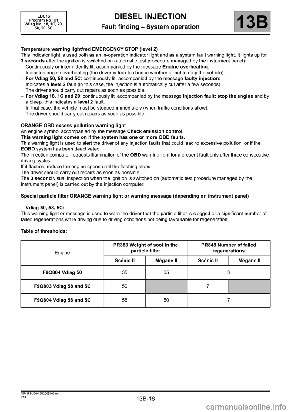
Temperature warning light/red EMERGENCY STOP (level 2)
This indicator light is used both as an in-operation indicator light and as a system fault warning light. It lights up for
3 seconds after the ignition is switched on (automatic test procedure managed by the instrument panel):
– Continuously or intermittently lit, accompanied by the message Engine overheating:
Indicates engine overheating (the driver is free to choose whether or not to stop the vehicle).
–For Vdiag 50, 58 and 5C: continuously lit, accompanied by the message faulty injection:
Indicates a level 2 fault (in this case, the injection is automatically cut after a few seconds).
The driver should carry out repairs as soon as possible.
–For Vdiag 18, 1C and 20: continuously lit, accompanied by the message Injection fault: stop the engine and by
a bleep, this indicates a level 2 fault.
In that case, the vehicle must be stopped immediately (when traffic conditions allow).
The driver should carry out repairs as soon as possible.
ORANGE OBD excess pollution warning light
An engine symbol accompanied by the message Check emission control.
This warning light comes on if the system has one or more OBD faults.
This warning light is used to alert the driver of any injection faults that could lead to excessive pollution, or if the
EOBD system has been deactivated.
The injection computer requests illumination of the OBD warning light for a present fault only after three consecutive
driving cycles.
If it flashes, reduce the engine speed until the flashing stops.
The driver should carry out repairs as soon as possible.
The 3 second visual inspection when the ignition is switched on (automatic test procedure managed by the
instrument panel) is carried out by the injection computer.
Special particle filter ORANGE warning light or warning message (depending on instrument panel)
– Vdiag 50, 58, 5C:
This warning light or message is used to warn the driver that the particle filter is clogged or a significant number of
failed regenerations while driving due to driving conditions not being favourable for regeneration.
Table of thresholds:
EnginePR383 Weight of soot in the
particle filterPR848 Number of failed
regenerations
Scénic II Mégane IIScénic II Mégane II
F9Q804 Vdiag 5035 35 3
F9Q803 Vdiag 58 and 5C50
7
F9Q804 Vdiag 58 and 5C58 50 7
Page 22 of 365
13B-22
MR-372-J84-13B200$144.mif
V13
DIESEL INJECTION
Fault finding – Replacement of components
EDC16
Program No: C1
Vdiag No: 18, 1C, 20,
50, 58, 5C
13B
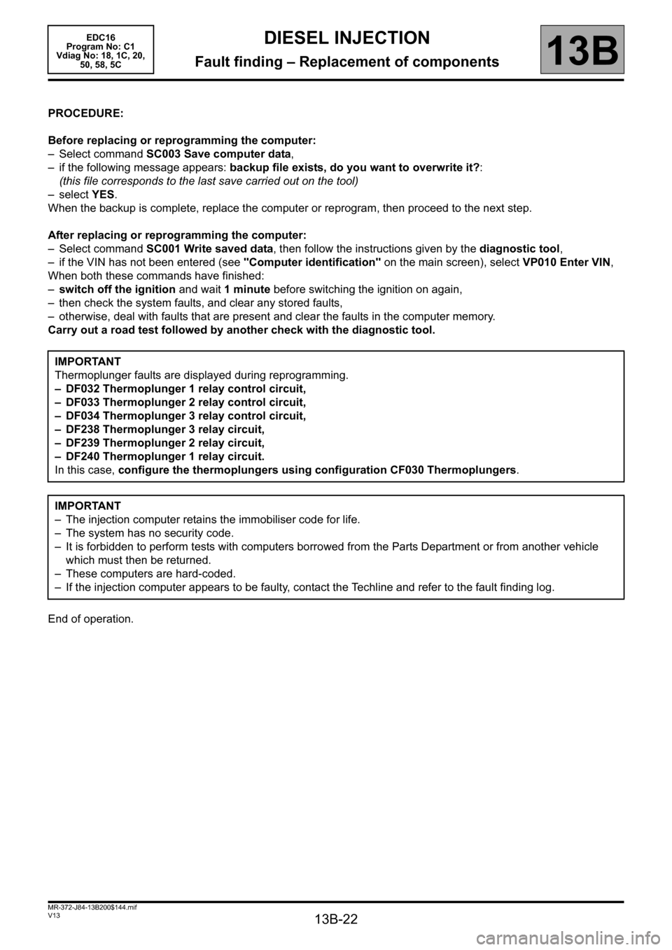
PROCEDURE:
Before replacing or reprogramming the computer:
– Select command SC003 Save computer data,
– if the following message appears: backup file exists, do you want to overwrite it?:
(this file corresponds to the last save carried out on the tool)
–select YES.
When the backup is complete, replace the computer or reprogram, then proceed to the next step.
After replacing or reprogramming the computer:
– Select command SC001 Write saved data, then follow the instructions given by the diagnostic tool,
– if the VIN has not been entered (see "Computer identification" on the main screen), select VP010 Enter VIN,
When both these commands have finished:
–switch off the ignition and wait 1minute before switching the ignition on again,
– then check the system faults, and clear any stored faults,
– otherwise, deal with faults that are present and clear the faults in the computer memory.
Carry out a road test followed by another check with the diagnostic tool.
End of operation.IMPORTANT
Thermoplunger faults are displayed during reprogramming.
– DF032 Thermoplunger 1 relay control circuit,
– DF033 Thermoplunger 2 relay control circuit,
– DF034 Thermoplunger 3 relay control circuit,
– DF238 Thermoplunger 3 relay circuit,
– DF239 Thermoplunger 2 relay circuit,
– DF240 Thermoplunger 1 relay circuit.
In this case, configure the thermoplungers using configuration CF030 Thermoplungers.
IMPORTANT
– The injection computer retains the immobiliser code for life.
– The system has no security code.
– It is forbidden to perform tests with computers borrowed from the Parts Department or from another vehicle
which must then be returned.
– These computers are hard-coded.
– If the injection computer appears to be faulty, contact the Techline and refer to the fault finding log.
Page 23 of 365
13B-23
MR-372-J84-13B200$144.mif
V13
DIESEL INJECTION
Fault finding – Replacement of components
EDC16
Program No: C1
Vdiag No: 18, 1C, 20,
50, 58, 5C
13B
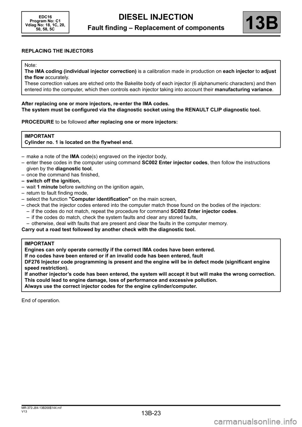
REPLACING THE INJECTORS
After replacing one or more injectors, re-enter the IMA codes.
The system must be configured via the diagnostic socket using the RENAULT CLIP diagnostic tool.
PROCEDURE to be followed after replacing one or more injectors:
– make a note of the IMA code(s) engraved on the injector body,
– enter these codes in the computer using command SC002 Enter injector codes, then follow the instructions
given by the diagnostic tool,
– once the command has finished,
– switch off the ignition,
–wait 1 minute before switching on the ignition again,
– return to fault finding mode,
– select the function "Computer identification" on the main screen,
– check that the injector codes entered into the computer match those found on the bodies of the injectors:
– if the codes do not match, repeat the procedure for command SC002 Enter injector codes.
– if the codes do match, check the system faults and clear any stored faults,
– otherwise, deal with faults that are present and clear the faults in the computer memory.
Carry out a road test followed by another check with the diagnostic tool.
End of operation.Note:
The IMA coding (individual injector correction) is a calibration made in production on each injector to adjust
the flow accurately.
These correction values are etched onto the Bakelite body of each injector (6 alphanumeric characters) and then
entered into the computer, which then controls each injector taking into account their manufacturing variance.
IMPORTANT
Cylinder no. 1 is located on the flywheel end.
IMPORTANT
Engines can only operate correctly if the correct IMA codes have been entered.
If no codes have been entered or if an invalid code has been entered, fault
DF276 Injector code programming is present and the engine will be in defect mode (significant engine
speed restriction).
If another injector’s code has been entered, the system will accept it but will make the wrong correction.
This could lead to engine damage, loss of performance and excessive pollution.
Always use the correct injector codes for the engine cylinder/computer.
Page 24 of 365
13B-24
MR-372-J84-13B200$144.mif
V13
DIESEL INJECTION
Fault finding – Replacement of components
EDC16
Program No: C1
Vdiag No: 18, 1C, 20,
50, 58, 5C
13B
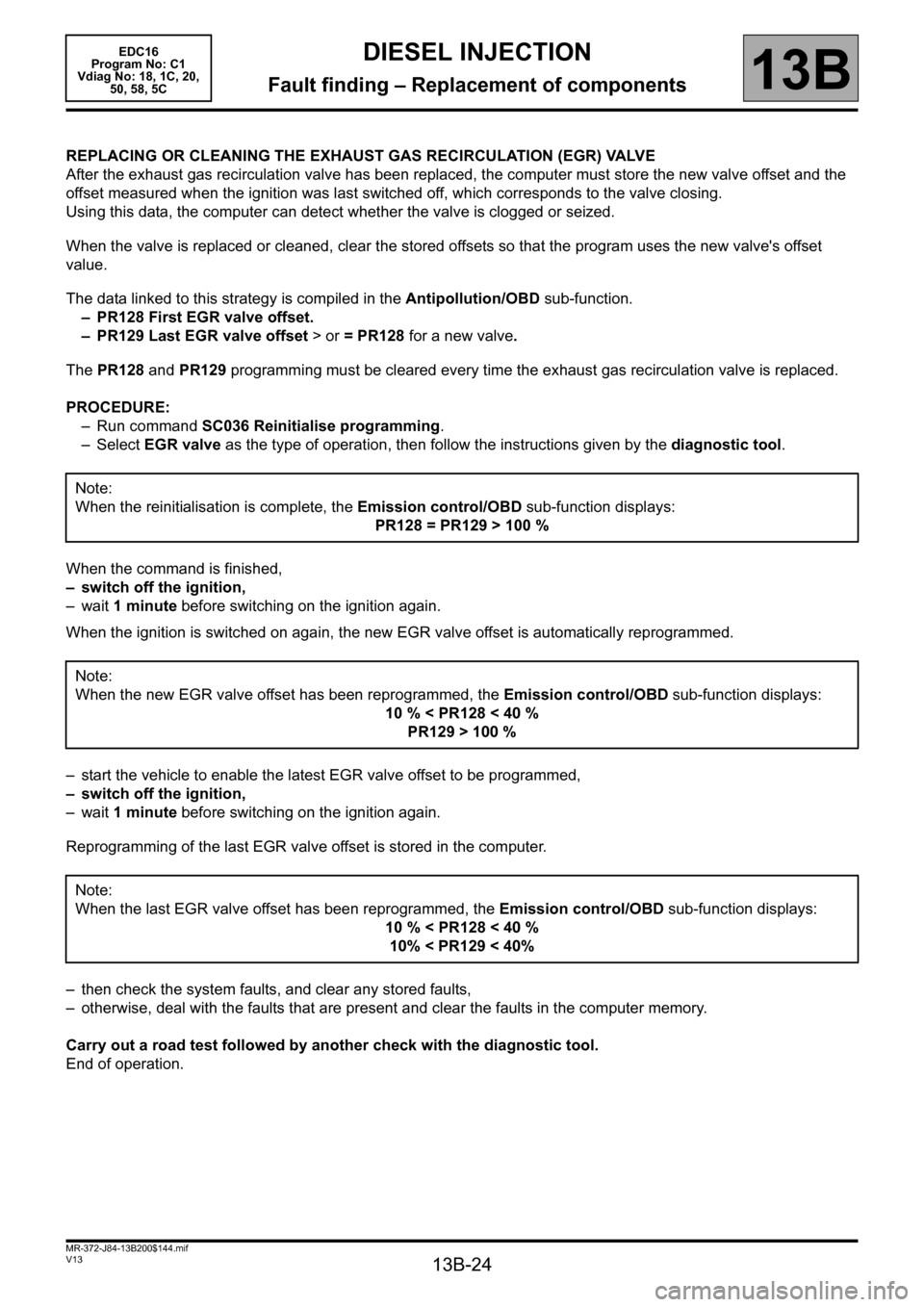
REPLACING OR CLEANING THE EXHAUST GAS RECIRCULATION (EGR) VALVE
After the exhaust gas recirculation valve has been replaced, the computer must store the new valve offset and the
offset measured when the ignition was last switched off, which corresponds to the valve closing.
Using this data, the computer can detect whether the valve is clogged or seized.
When the valve is replaced or cleaned, clear the stored offsets so that the program uses the new valve's offset
value.
The data linked to this strategy is compiled in the Antipollution/OBD sub-function.
– PR128 First EGR valve offset.
– PR129 Last EGR valve offset > or = PR128 for a new valve.
The PR128 and PR129 programming must be cleared every time the exhaust gas recirculation valve is replaced.
PROCEDURE:
– Run command SC036 Reinitialise programming.
–Select EGR valve as the type of operation, then follow the instructions given by the diagnostic tool.
When the command is finished,
– switch off the ignition,
–wait 1 minute before switching on the ignition again.
When the ignition is switched on again, the new EGR valve offset is automatically reprogrammed.
– start the vehicle to enable the latest EGR valve offset to be programmed,
– switch off the ignition,
–wait 1 minute before switching on the ignition again.
Reprogramming of the last EGR valve offset is stored in the computer.
– then check the system faults, and clear any stored faults,
– otherwise, deal with the faults that are present and clear the faults in the computer memory.
Carry out a road test followed by another check with the diagnostic tool.
End of operation.Note:
When the reinitialisation is complete, the Emission control/OBD sub-function displays:
PR128 = PR129 > 100 %
Note:
When the new EGR valve offset has been reprogrammed, the Emission control/OBD sub-function displays:
10 % < PR128 < 40 %
PR129 > 100 %
Note:
When the last EGR valve offset has been reprogrammed, the Emission control/OBD sub-function displays:
10 % < PR128 < 40 %
10% < PR129 < 40%
Page 25 of 365
13B-25
MR-372-J84-13B200$144.mif
V13
DIESEL INJECTION
Fault finding – Replacement of components
EDC16
Program No: C1
Vdiag No: 18, 1C, 20,
50, 58, 5C
13B
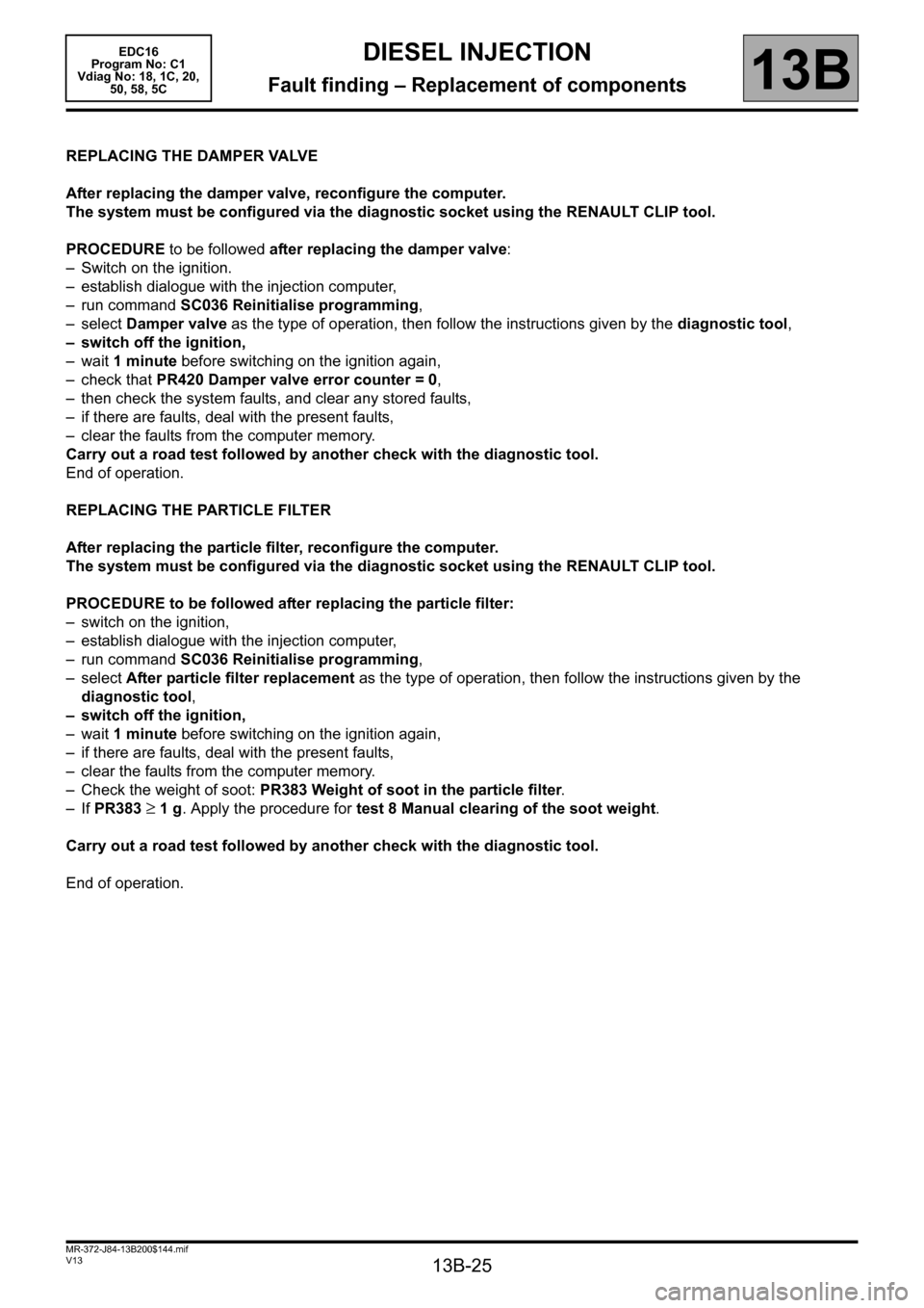
REPLACING THE DAMPER VALVE
After replacing the damper valve, reconfigure the computer.
The system must be configured via the diagnostic socket using the RENAULT CLIP tool.
PROCEDURE to be followed after replacing the damper valve:
– Switch on the ignition.
– establish dialogue with the injection computer,
– run command SC036 Reinitialise programming,
–select Damper valve as the type of operation, then follow the instructions given by the diagnostic tool,
– switch off the ignition,
–wait 1 minute before switching on the ignition again,
– check that PR420 Damper valve error counter = 0,
– then check the system faults, and clear any stored faults,
– if there are faults, deal with the present faults,
– clear the faults from the computer memory.
Carry out a road test followed by another check with the diagnostic tool.
End of operation.
REPLACING THE PARTICLE FILTER
After replacing the particle filter, reconfigure the computer.
The system must be configured via the diagnostic socket using the RENAULT CLIP tool.
PROCEDURE to be followed after replacing the particle filter:
– switch on the ignition,
– establish dialogue with the injection computer,
– run command SC036 Reinitialise programming,
–select After particle filter replacement as the type of operation, then follow the instructions given by the
diagnostic tool,
– switch off the ignition,
–wait 1 minute before switching on the ignition again,
– if there are faults, deal with the present faults,
– clear the faults from the computer memory.
– Check the weight of soot: PR383 Weight of soot in the particle filter.
– If PR383
≥ 1 g. Apply the procedure for test 8 Manual clearing of the soot weight.
Carry out a road test followed by another check with the diagnostic tool.
End of operation.
Page 33 of 365
13B-33
MR-372-J84-13B200$252.mif
V13
13B
DIESEL INJECTION
Fault finding – Interpretation of faults
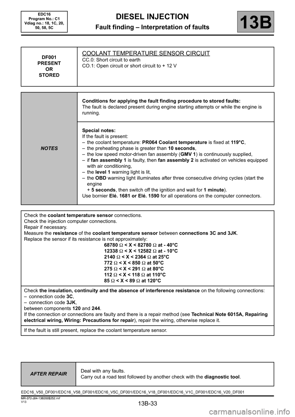
DF001
PRESENT
OR
STOREDCOOLANT TEMPERATURE SENSOR CIRCUIT
CC.0: Short circuit to earth
CO.1: Open circuit or short circuit to + 12 V
NOTESConditions for applying the fault finding procedure to stored faults:
The fault is declared present during engine starting attempts or while the engine is
running.
Special notes:
If the fault is present:
– the coolant temperature: PR064 Coolant temperature is fixed at 11 9 ° C,
– the preheating phase is greater than 10 seconds,
– the low speed motor-driven fan assembly (GMV 1) is continuously supplied,
–if fan assembly 1 is faulty, then fan assembly 2 is activated on vehicles equipped
with air conditioning,
– the level 1 warning light is lit,
– the OBD warning light illuminates after three consecutive driving cycles (start the
engine
+ 5 seconds, then switch off the ignition and wait for 1 minute).
Use bornier Elé. 1681 or Elé. 1590 for all operations on the computer connectors.
Check the coolant temperature sensor connections.
Check the injection computer connections.
Repair if necessary.
Measure the resistance of the coolant temperature sensor between connections 3C and 3JK.
Replace the sensor if its resistance is not approximately:
68780 Ω < X < 82780 Ω at - 40°C
12338 Ω < X < 12582 Ω at - 10°C
2140 Ω < X < 2364 Ω at 25°C
772 Ω < X < 850 Ω at 50°C
275 Ω < X < 291 Ω at 80°C
11 2 Ω < X < 118 Ω at 110°C
85 Ω < X < 89 Ω at 120°C
Check the insulation, continuity and the absence of interference resistance on the following connections:
– connection code3C,
– connection code 3JK,
between components 120 and 244.
If the connection or connections are faulty and there is a repair method (see Technical Note 6015A, Repairing
electrical wiring, Wiring: Precautions for repair), repair the wiring, otherwise replace it.
If the fault is still present, replace the coolant temperature sensor.
AFTER REPAIRDeal with any faults.
Carry out a road test followed by another check with the diagnostic tool.
EDC16_V50_DF001/EDC16_V58_DF001/EDC16_V5C_DF001/EDC16_V18_DF001/EDC16_V1C_DF001/EDC16_V20_DF001EDC16
Program No.: C1
Vdiag no.: 18, 1C, 20,
50, 58, 5C
MR-372-J84-13B200$252.mif