ESP RENAULT SCENIC 2011 J95 / 3.G Engine And Peripherals EDC16C36 Workshop Manual
[x] Cancel search | Manufacturer: RENAULT, Model Year: 2011, Model line: SCENIC, Model: RENAULT SCENIC 2011 J95 / 3.GPages: 431, PDF Size: 2.03 MB
Page 336 of 431
13B-336V9 MR-372-J84-13B450$152.mif
DIESEL INJECTION
Fault finding – Interpretation of parameters13B
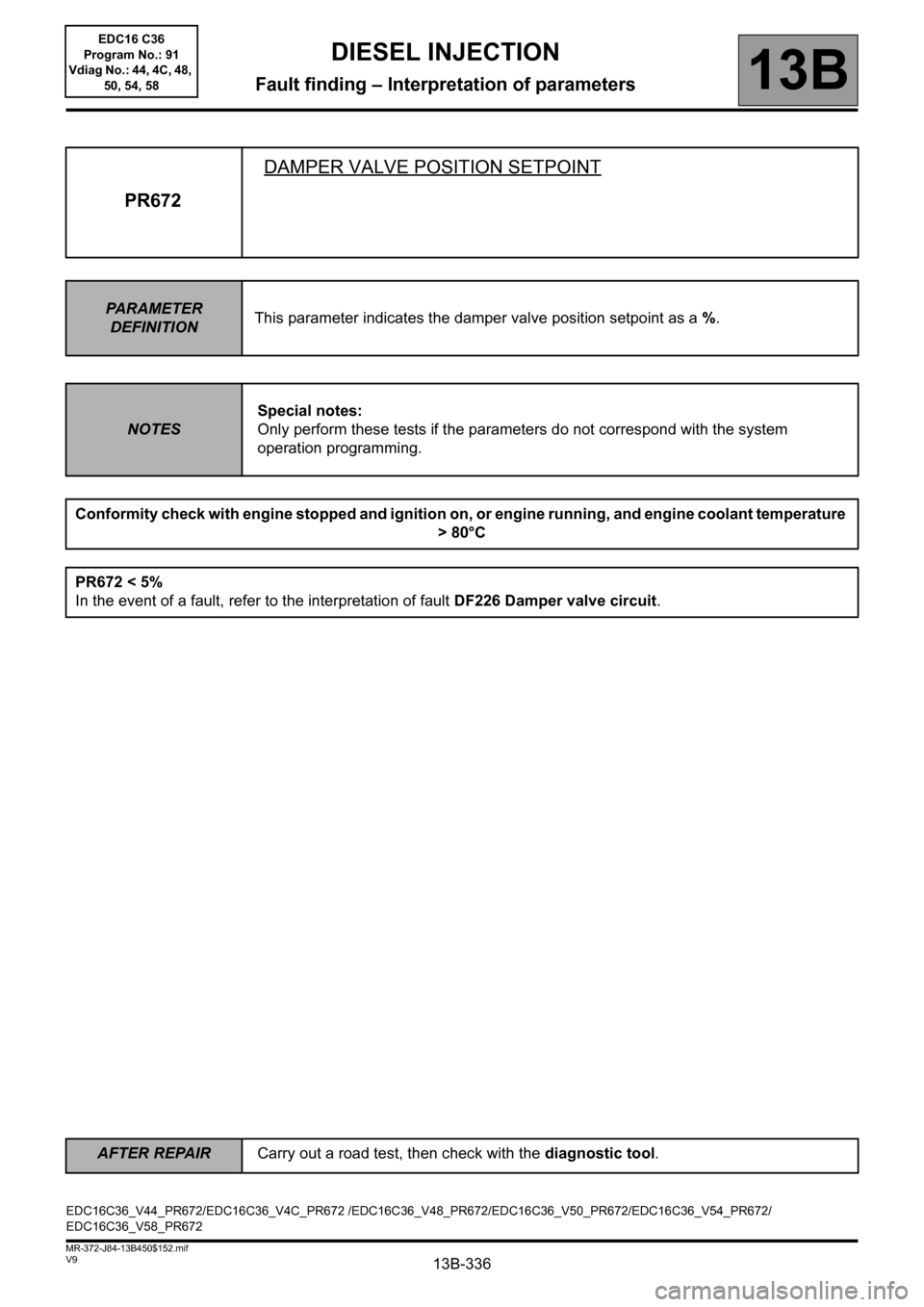
PR672DAMPER VALVE POSITION SETPOINT
PARAMETER
DEFINITIONThis parameter indicates the damper valve position setpoint as a %.
NOTESSpecial notes:
Only perform these tests if the parameters do not correspond with the system
operation programming.
Conformity check with engine stopped and ignition on, or engine running, and engine coolant temperature
> 80°C
PR672 < 5%
In the event of a fault, refer to the interpretation of fault DF226 Damper valve circuit.
EDC16C36_V44_PR672/EDC16C36_V4C_PR672 /EDC16C36_V48_PR672/EDC16C36_V50_PR672/EDC16C36_V54_PR672/
EDC16C36_V58_PR672
AFTER REPAIRCarry out a road test, then check with the diagnostic tool.
EDC16 C36
Program No.: 91
Vdiag No.: 44, 4C, 48,
50, 54, 58
Page 337 of 431
13B-337V9 MR-372-J84-13B450$152.mif
DIESEL INJECTION
Fault finding – Interpretation of parameters13B
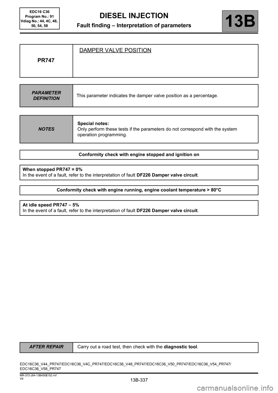
PR747DAMPER VALVE POSITION
PARAMETER
DEFINITIONThis parameter indicates the damper valve position as a percentage.
NOTESSpecial notes:
Only perform these tests if the parameters do not correspond with the system
operation programming.
Conformity check with engine stopped and ignition on
When stopped PR747 = 0%
In the event of a fault, refer to the interpretation of fault DF226 Damper valve circuit.
Conformity check with engine running, engine coolant temperature > 80°C
At idle speed PR747 ≈ 5%
In the event of a fault, refer to the interpretation of fault DF226 Damper valve circuit.
EDC16C36_V44_PR747/EDC16C36_V4C_PR747/EDC16C36_V48_PR747/EDC16C36_V50_PR747/EDC16C36_V54_PR747/
EDC16C36_V58_PR747
AFTER REPAIRCarry out a road test, then check with the diagnostic tool.
EDC16 C36
Program No.: 91
Vdiag No.: 44, 4C, 48,
50, 54, 58
Page 346 of 431
13B-346V9 MR-372-J84-13B450$152.mif
DIESEL INJECTION
Fault finding – Interpretation of parameters13B
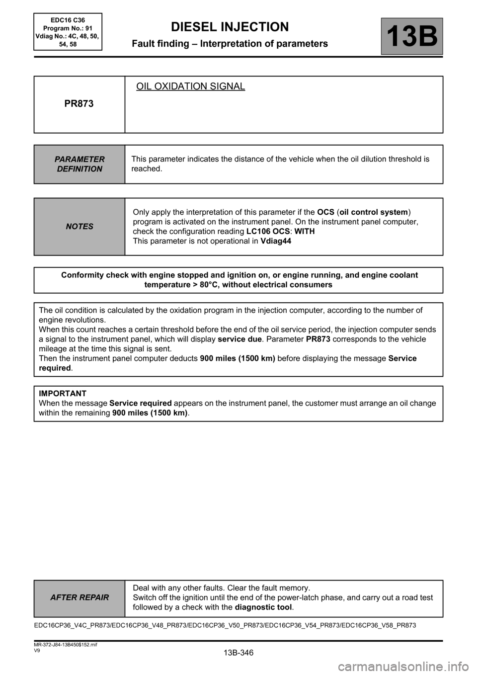
PR873OIL OXIDATION SIGNAL
PARAMETER
DEFINITIONThis parameter indicates the distance of the vehicle when the oil dilution threshold is
reached.
NOTESOnly apply the interpretation of this parameter if the OCS (oil control system)
program is activated on the instrument panel. On the instrument panel computer,
check the configuration reading LC106 OCS: WITH
This parameter is not operational in Vdiag44
Conformity check with engine stopped and ignition on, or engine running, and engine coolant
temperature > 80°C, without electrical consumers
The oil condition is calculated by the oxidation program in the injection computer, according to the number of
engine revolutions.
When this count reaches a certain threshold before the end of the oil service period, the injection computer sends
a signal to the instrument panel, which will display service due. Parameter PR873 corresponds to the vehicle
mileage at the time this signal is sent.
Then the instrument panel computer deducts 900 miles (1500 km) before displaying the message Service
required.
IMPORTANT
When the message Service required appears on the instrument panel, the customer must arrange an oil change
within the remaining 900 miles (1500 km).
EDC16CP36_V4C_PR873/EDC16CP36_V48_PR873/EDC16CP36_V50_PR873/EDC16CP36_V54_PR873/EDC16CP36_V58_PR873
AFTER REPAIRDeal with any other faults. Clear the fault memory.
Switch off the ignition until the end of the power-latch phase, and carry out a road test
followed by a check with the diagnostic tool.
EDC16 C36
Program No.: 91
Vdiag No.: 4C, 48, 50,
54, 58
Page 348 of 431
13B-348V9 MR-372-J84-13B450$152.mif
DIESEL INJECTION
Fault finding – Interpretation of parameters13B
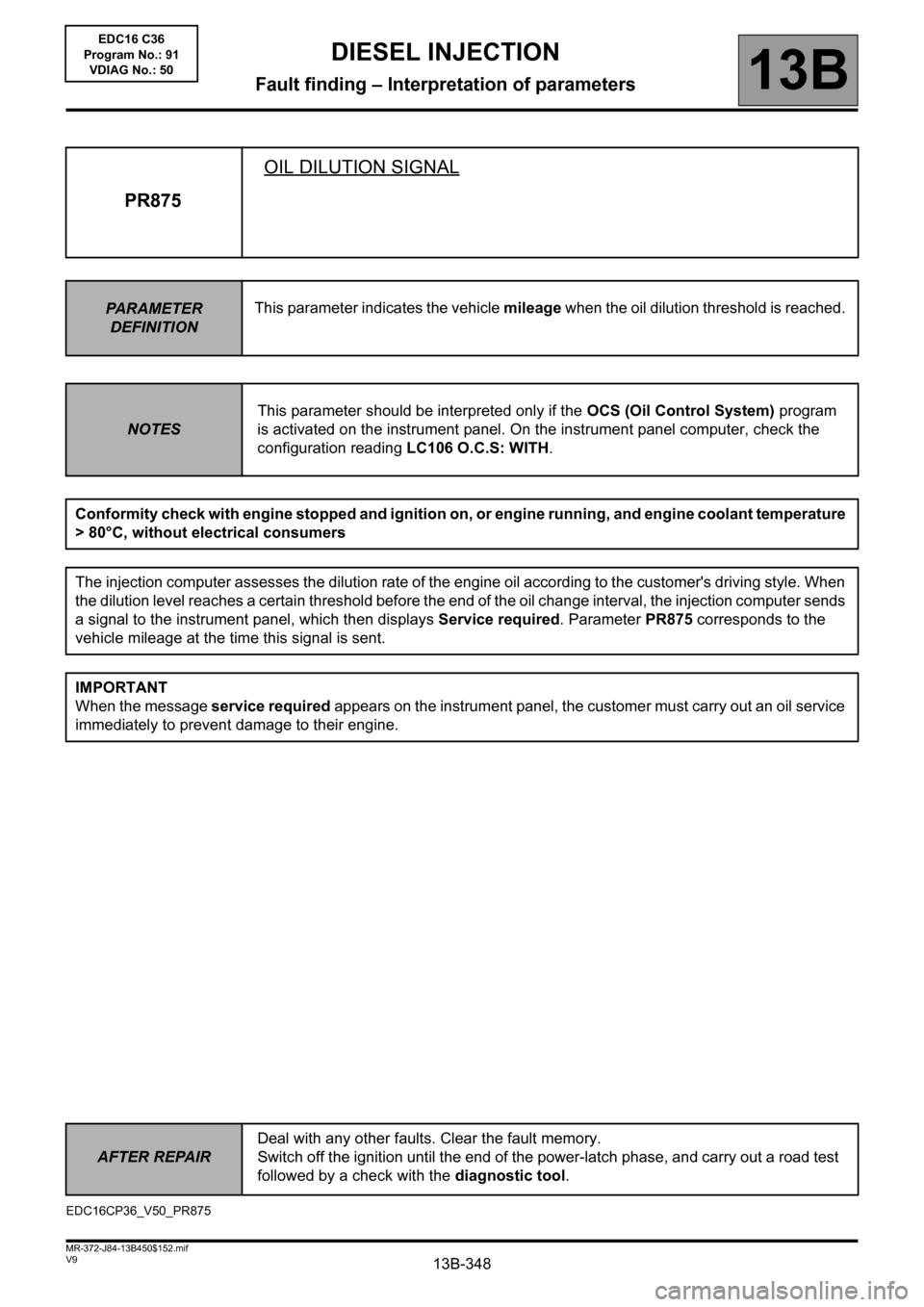
PR875OIL DILUTION SIGNAL
PARAMETER
DEFINITIONThis parameter indicates the vehicle mileage when the oil dilution threshold is reached.
NOTESThis parameter should be interpreted only if the OCS (Oil Control System) program
is activated on the instrument panel. On the instrument panel computer, check the
configuration reading LC106 O.C.S: WITH.
Conformity check with engine stopped and ignition on, or engine running, and engine coolant temperature
> 80°C, without electrical consumers
The injection computer assesses the dilution rate of the engine oil according to the customer's driving style. When
the dilution level reaches a certain threshold before the end of the oil change interval, the injection computer sends
a signal to the instrument panel, which then displays Service required. Parameter PR875 corresponds to the
vehicle mileage at the time this signal is sent.
IMPORTANT
When the message service required appears on the instrument panel, the customer must carry out an oil service
immediately to prevent damage to their engine.
EDC16CP36_V50_PR875EDC16 C36
Program No.: 91
VDIAG No.: 50
AFTER REPAIRDeal with any other faults. Clear the fault memory.
Switch off the ignition until the end of the power-latch phase, and carry out a road test
followed by a check with the diagnostic tool.
Page 352 of 431
13B-352
AFTER REPAIRRepeat the conformity check in the interpretation of statuses and parameters
V9 MR-372-J84-13B450$170.mif
DIESEL INJECTION
Fault finding – Interpretation of commands13B
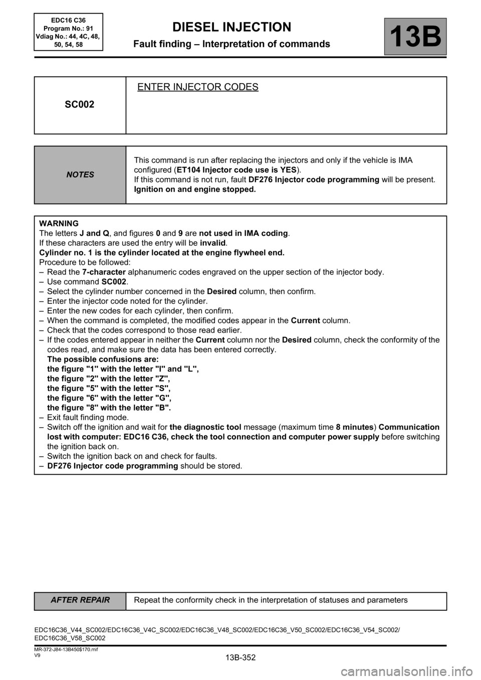
SC002ENTER INJECTOR CODES
NOTESThis command is run after replacing the injectors and only if the vehicle is IMA
configured (ET104 Injector code use is YES).
If this command is not run, fault DF276 Injector code programming will be present.
Ignition on and engine stopped.
WARNING
The letters J and Q, and figures 0 and 9 are not used in IMA coding.
If these characters are used the entry will be invalid.
Cylinder no. 1 is the cylinder located at the engine flywheel end.
Procedure to be followed:
– Read the 7-character alphanumeric codes engraved on the upper section of the injector body.
– Use command SC002.
– Select the cylinder number concerned in the Desired column, then confirm.
– Enter the injector code noted for the cylinder.
– Enter the new codes for each cylinder, then confirm.
– When the command is completed, the modified codes appear in the Current column.
– Check that the codes correspond to those read earlier.
– If the codes entered appear in neither the Current column nor the Desired column, check the conformity of the
codes read, and make sure the data has been entered correctly.
The possible confusions are:
the figure "1" with the letter "I" and "L",
the figure "2" with the letter "Z",
the figure "5" with the letter "S",
the figure "6" with the letter "G",
the figure "8" with the letter "B".
– Exit fault finding mode.
– Switch off the ignition and wait for the diagnostic tool message (maximum time 8minutes) Communication
lost with computer: EDC16 C36, check the tool connection and computer power supply before switching
the ignition back on.
– Switch the ignition back on and check for faults.
–DF276 Injector code programming should be stored.
EDC16C36_V44_SC002/EDC16C36_V4C_SC002/EDC16C36_V48_SC002/EDC16C36_V50_SC002/EDC16C36_V54_SC002/
EDC16C36_V58_SC002EDC16 C36
Program No.: 91
Vdiag No.: 44, 4C, 48,
50, 54, 58
Page 354 of 431
13B-354
AFTER REPAIRRepeat the conformity check in the interpretation of statuses and parameters
V9 MR-372-J84-13B450$170.mif
DIESEL INJECTION
Fault finding – Interpretation of commands13B
SC003SAVE COMPUTER DATA
NOTESThis save is performed before reprogramming or replacing the computer.
Ignition on and engine stopped.
On the CLIP tool, select scenario SC003 Save computer data.
If the following message appears:
"a saved file exists, do you want to overwrite this data?":
(this file corresponds to the last save made on thediagnostic tool)
select "YES".
Confirming this command saves the following vehicle-specific data:
– injector codes,
– the egr valve data programming;
– options available on the vehicle and managed by the computer (e.g.: air conditioning).
This information will be saved in the CLIP tool.
After saving has finished, use the command SC001 Enter saved data to be able to set the new computer
parameters, after programming and reprogramming.
EDC16C36_V44_SC003/EDC16C36_V4C_SC003/EDC16C36_V48_SC003/EDC16C36_V50_SC003/EDC16C36_V54_SC003/
EDC16C36_V58_SC003EDC16 C36
Program No.: 91
Vdiag No.: 44, 4C, 48,
50, 54, 58
Page 367 of 431
13B-367
AFTER REPAIRRepeat the conformity check in the interpretation of statuses and parameters
V9 MR-372-J84-13B450$170.mif
DIESEL INJECTION
Fault finding – Interpretation of commands13B
AC004TURBOCHARGING SOLENOID VALVE
NOTESPerform this fault finding procedure:
– following interpretation of an unresolved fault or
– after processing the interpretation of PR041 Turbocharging pressure or
– after a customer complaint (loss of power, smoke etc.).
Ignition on and engine stopped.
Use Wiring Diagram Technical Note, Mégane II ph2, Scénic II ph2.
1. The following procedure is for checking that the turbocharger and its control circuit are working
properly.
Check the sealing of the high pressure air circuit, run test 3 Low pressure circuit check
Pipe not joined or pierced, pressure sensor disconnected or poorly fitted (seal present), exchanger pierced.
To test the exchanger: stabilise the engine speed between 3500 and 4000 rpm with the vehicle stopped and check
that there are no leaks.
Measure the resistance of the turbocharging pressure solenoid valve between the following connections:
– Connection code 3MG,
– Connection code 3FB,
of component 1475.
Replace the solenoid valve if its resistance is not: 20 Ω ± 2 at +23°C.
Check the continuity, insulation, and the absence of interference resistance on the following connections:
– Connection code 3MG between components 1475 and 120.
– Connection code 3FB between components 1475 and 983.
Run command AC004, if a faint whistling noise is heard along with a clicking from the solenoid valve, go to step
2, otherwise check the operation of the computer output stage:
Vehicle under + after ignition feed, clear the faults displayed by the diagnostic tool.
With the voltmeter in the direct current position:
With the turbocharging solenoid valve connected, connect the voltmeter earth lead to connection 3MG of
component 1475 and the positive lead to connection3FB.
Run command AC004, the voltmeter should display four successive voltages of 2.4 V ± 0.2 V.
If the measurement is not correct, contact the Techline.
EDC16C36_V44_AC004/EDC16C36_V4C_AC004/EDC16C36_V48_AC004/EDC16C36_V50_AC004/EDC16C36_V54_AC004/
EDC16C36_V58_AC004EDC16 C36
Program No.: 91
Vdiag No.: 44, 4C, 48,
50, 54, 58
Page 369 of 431
13B-369
AFTER REPAIRRepeat the conformity check in the interpretation of statuses and parameters
V9 MR-372-J84-13B450$170.mif
DIESEL INJECTION
Fault finding – Interpretation of commands13B
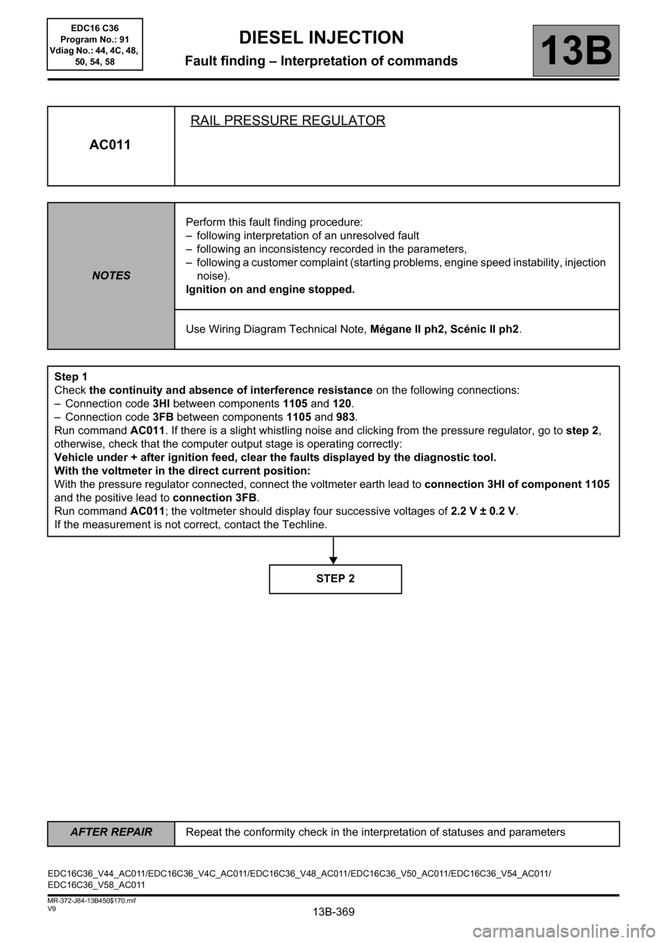
AC011RAIL PRESSURE REGULATOR
NOTESPerform this fault finding procedure:
– following interpretation of an unresolved fault
– following an inconsistency recorded in the parameters,
– following a customer complaint (starting problems, engine speed instability, injection
noise).
Ignition on and engine stopped.
Use Wiring Diagram Technical Note, Mégane II ph2, Scénic II ph2.
Step 1
Check the continuity and absence of interference resistance on the following connections:
– Connection code 3HI between components 1105 and 120.
– Connection code 3FB between components 1105 and 983.
Run command AC011. If there is a slight whistling noise and clicking from the pressure regulator, go to step 2,
otherwise, check that the computer output stage is operating correctly:
Vehicle under + after ignition feed, clear the faults displayed by the diagnostic tool.
With the voltmeter in the direct current position:
With the pressure regulator connected, connect the voltmeter earth lead to connection 3HI of component 1105
and the positive lead to connection 3FB.
Run command AC011; the voltmeter should display four successive voltages of 2.2 V ± 0.2 V.
If the measurement is not correct, contact the Techline.
STEP 2
EDC16C36_V44_AC011/EDC16C36_V4C_AC011/EDC16C36_V48_AC011/EDC16C36_V50_AC011/EDC16C36_V54_AC011/
EDC16C36_V58_AC011EDC16 C36
Program No.: 91
Vdiag No.: 44, 4C, 48,
50, 54, 58
Page 393 of 431
13B-393
AFTER REPAIRCarry out a road test followed by a complete check with the diagnostic tool.
V9 MR-372-J84-13B450$190.mif
DIESEL INJECTION
Fault finding – Fault Finding Chart13B
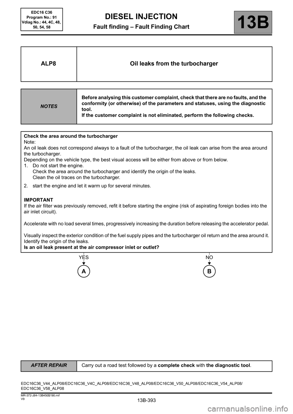
ALP8 Oil leaks from the turbocharger
NOTESBefore analysing this customer complaint, check that there are no faults, and the
conformity (or otherwise) of the parameters and statuses, using the diagnostic
tool.
If the customer complaint is not eliminated, perform the following checks.
Check the area around the turbocharger
Note:
An oil leak does not correspond always to a fault of the turbocharger, the oil leak can arise from the area around
the turbocharger.
Depending on the vehicle type, the best visual access will be either from above or from below.
1. Do not start the engine.
Check the area around the turbocharger and identify the origin of the leaks.
Clean the oil traces on the turbocharger.
2. start the engine and let it warm up for several minutes.
IMPORTANT
If the air filter was previously removed, refit it before starting the engine (risk of aspirating foreign bodies into the
air inlet circuit).
Accelerate with no load several times, progressively increasing the duration before releasing the accelerator pedal.
Visually inspect the exterior condition of the fuel supply pipes and the turbocharger oil return and the area around it.
Identify the origin of the leaks.
Is an oil leak present at the air compressor inlet or outlet?
YESNO
AB
EDC16C36_V44_ALP08/EDC16C36_V4C_ALP08/EDC16C36_V48_ALP08/EDC16C36_V50_ALP08/EDC16C36_V54_ALP08/
EDC16C36_V58_ALP08EDC16 C36
Program No.: 91
Vdiag No.: 44, 4C, 48,
50, 54, 58
Page 398 of 431
13B-398
AFTER REPAIRCarry out a road test followed by a complete check with the diagnostic tool.
V9 MR-372-J84-13B450$190.mif
DIESEL INJECTION
Fault finding – Fault Finding Chart13B
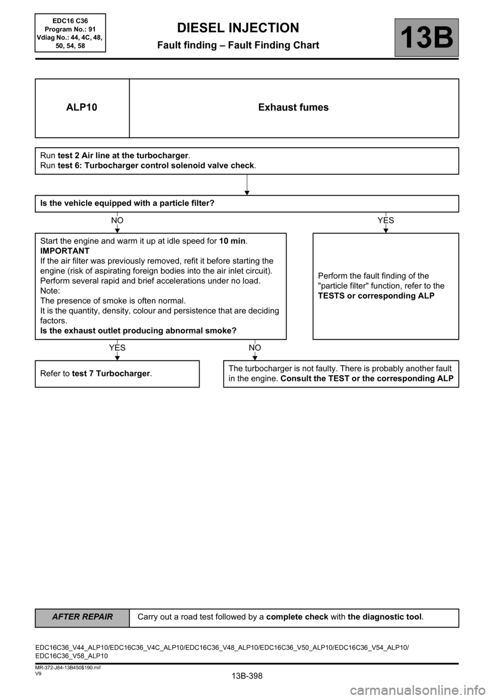
ALP10 Exhaust fumes
Run test 2 Air line at the turbocharger.
Run test 6: Turbocharger control solenoid valve check.
Is the vehicle equipped with a particle filter?
Start the engine and warm it up at idle speed for 10 min.
IMPORTANT
If the air filter was previously removed, refit it before starting the
engine (risk of aspirating foreign bodies into the air inlet circuit).
Perform several rapid and brief accelerations under no load.
Note:
The presence of smoke is often normal.
It is the quantity, density, colour and persistence that are deciding
factors.
Is the exhaust outlet producing abnormal smoke?Perform the fault finding of the
"particle filter" function, refer to the
TESTS or corresponding ALP
Refer to test 7 Turbocharger.The turbocharger is not faulty. There is probably another fault
in the engine. Consult the TEST or the corresponding ALP
NOYES
YESNO
EDC16C36_V44_ALP10/EDC16C36_V4C_ALP10/EDC16C36_V48_ALP10/EDC16C36_V50_ALP10/EDC16C36_V54_ALP10/
EDC16C36_V58_ALP10EDC16 C36
Program No.: 91
Vdiag No.: 44, 4C, 48,
50, 54, 58