edc16 RENAULT SCENIC 2011 J95 / 3.G Engine And Peripherals EDC16C36 Workshop Manual
[x] Cancel search | Manufacturer: RENAULT, Model Year: 2011, Model line: SCENIC, Model: RENAULT SCENIC 2011 J95 / 3.GPages: 431, PDF Size: 2.03 MB
Page 162 of 431

13B-162
AFTER REPAIRDeal with any other faults. Clear the fault memory.
Switch off the ignition until the end of the power-latch phase, and carry out a road test
followed by a check using the diagnostic tool.
V9 MR-372-J84-13B450$103.mif
DIESEL INJECTION
Fault finding – Interpretation of faults13B
DF308
CONTINUED
Check that there are no leaks or blockages in the exhaust pipe,
Repair if necessary
Carry out an After-Sales regeneration.
Run command SC017 "Particle filter regeneration" (see Interpretation of commands).
Clear fault DF308 Present or Stored.
Apply TEST 4 Turbocharged air inlet circuit check.
If the fault is still present, contact the Techline.
EDC16 C36
Program No.: 91
Vdiag No.: 48, 58
Page 163 of 431

13B-163
AFTER REPAIRDeal with any other faults. Clear the fault memory.
Switch off the ignition until the end of the power-latch phase, and carry out a road test
followed by a check using the diagnostic tool.
V9 MR-372-J84-13B450$103.mif
DIESEL INJECTION
Fault finding – Interpretation of faults13B
*temp: temperature
DF309
PRESENT
OR
STOREDPARTICLE FILTER DOWNSTREAM TEMP.* SENSOR
CO.1: Open circuit or short circuit to +12 V
CC.0: Short circuit to earth
NOTESConditions for applying fault finding procedures to stored faults:
The fault becomes present if:
– ignition is on (CC.0),
– following a road test, engine warm (CO.1).
IMPORTANT
The particle filter downstream temperature sensor only measures temperatures
greater than 50°C.
Use the Wiring Diagram Technical Note, Mégane II ph2, Scénic II ph2.
CC.0
NOTESNone.
Check the condition of the particle filter downstream temperature sensor connector.
Check the condition of the engine management computer connector.
If the connector or connectors are faulty and if there is a repair procedure (see Technical Note 6015A, Repairing
electrical wiring, Wiring: Precautions for repair), repair the connector, otherwise replace the wiring.
Check the insulation from earth of the following connections:
– connection code3TG,
– connection code3XU,
between components 120 and 1288.
If the connection or connections are faulty and there is a repair procedure (see Technical Note 6015A, Electrical
wiring repair, Wiring: Precautions for repair), repair the wiring, otherwise replace it.
If the fault is still present, replace the particle filter downstream temperature sensor.
EDC16C36_V48_DF309/EDC16C36_V58_DF309EDC16 C36
Program No.: 91
Vdiag No.: 48, 58
Page 164 of 431
13B-164
AFTER REPAIRDeal with any other faults. Clear the fault memory.
Switch off the ignition until the end of the power-latch phase, and carry out a road test
followed by a check using the diagnostic tool.
V9 MR-372-J84-13B450$103.mif
DIESEL INJECTION
Fault finding – Interpretation of faults13B
DF309
CONTINUED
CO.1NOTESNone.
Check the condition of the particle filter downstream temperature sensor connector.
Check the condition of the engine management computer connector.
If the connector or connectors are faulty and if there is a repair procedure (see Technical Note 6015A, Repairing
electrical wiring, Wiring: Precautions for repair), repair the connector, otherwise replace the wiring.
Check the continuity and insulation from + 12 V of the following connections:
– connection code3TG,
– connection code3XU,
between components 120 and 1288.
If the connection or connections are faulty and there is a repair procedure (see Technical Note 6015A, Electrical
wiring repair, Wiring: Precautions for repair), repair the wiring, otherwise replace it.
If the fault is still present, replace the particle filter downstream temperature sensor.
EDC16 C36
Program No.: 91
Vdiag No.: 48, 58
Page 165 of 431
13B-165
AFTER REPAIRDeal with any other faults. Clear the fault memory.
Switch off the ignition until the end of the power-latch phase, and carry out a road test
followed by a check using the diagnostic tool.
V9 MR-372-J84-13B450$103.mif
DIESEL INJECTION
Fault finding – Interpretation of faults13B
DF310
PRESENT
OR
STOREDPARTICLE FILTER UPSTREAM TEMP.* SENSOR
CO.1: Open circuit or short circuit to +12 V
CC.0: Short circuit to earth
NOTESConditions for applying fault finding procedures to stored faults:
The fault becomes present if:
– ignition is on (CC.0),
– following a road test, engine warm (CO.1).
Special notes:
If the fault is present:
– particle filter regeneration is inhibited,
–the level 1 warning light is lit,
–the OBD warning light comes on after three consecutive driving cycles (start
+5 seconds, switch off the ignition and wait 1 minute).
IMPORTANT
The particle filter upstream temperature sensor only measures temperatures
above 50°C.
Use the Wiring Diagram Technical Note, Mégane II ph2, Scénic II ph2.
EDC16C36_V48_DF310/EDC16C36_V50_DF310/EDC16C36_V58_DF310EDC16 C36
Program No.: 91
Vdiag No.: 48, 50, 58
Page 166 of 431
13B-166
AFTER REPAIRDeal with any other faults. Clear the fault memory.
Switch off the ignition until the end of the power-latch phase, and carry out a road test
followed by a check using the diagnostic tool.
V9 MR-372-J84-13B450$103.mif
DIESEL INJECTION
Fault finding – Interpretation of faults13B
*temp: temperature
DF310
CONTINUED 1
CC.0NOTESNone.
Check the condition of the particle filter upstream temperature sensor connector.
Check the condition of the engine management computer connector.
If the connector or connectors are faulty and if there is a repair procedure (see Technical Note 6015A, Repairing
electrical wiring, Wiring: Precautions for repair), repair the connector, otherwise replace the wiring.
Check the insulation from earth of the following connections:
– connection code3XT,
– connection code3TD,
between components 120 and 1287.
If the connection or connections are faulty and there is a repair procedure (see Technical Note 6015A, Electrical
wiring repair, Wiring: Precautions for repair), repair the wiring, otherwise replace it.
If the wiring of the particle filter downstream temperature sensor, component code 1288, is present (with or without
the sensor being present), check the electrical insulation in relation to + 12 V between the following connections:
•3XU between components 120 and 1288,
•3TG between components 120 and 1288.
If the connection or connections are faulty and there is a repair procedure (see Technical Note 6015A, Electrical
wiring repair, Wiring: Precautions for repair), repair the wiring, otherwise replace it.
If the fault is still present, replace the particle filter upstream temperature sensor.
EDC16 C36
Program No.: 91
Vdiag No.: 48, 50, 58
Page 167 of 431
13B-167
AFTER REPAIRDeal with any other faults. Clear the fault memory.
Switch off the ignition until the end of the power-latch phase, and carry out a road test
followed by a check using the diagnostic tool.
V9 MR-372-J84-13B450$103.mif
DIESEL INJECTION
Fault finding – Interpretation of faults13B
DF310
CONTINUED 2
CO.1NOTESNone.
Check the condition of the particle filter upstream temperature sensor connector.
Check the condition of the engine management computer connector.
If the connector or connectors are faulty and if there is a repair procedure (see Technical Note 6015A, Repairing
electrical wiring, Wiring: Precautions for repair), repair the connector, otherwise replace the wiring.
Check the continuity and insulation from + 12 V of the following connections:
– connection code3XT,
– connection code3TD,
between components 120 and 1287.
If the connection or connections are faulty and there is a repair procedure (see Technical Note 6015A, Electrical
wiring repair, Wiring: Precautions for repair), repair the wiring, otherwise replace it.
If the fault is still present, replace the particle filter upstream temperature sensor.
EDC16 C36
Program No.: 91
Vdiag No.: 48, 50, 58
Page 168 of 431
13B-168
AFTER REPAIRDeal with any other faults. Clear the fault memory.
Switch off the ignition, wait for the end of the power-latch phase and perform a road
test followed by a check using the diagnostic tool.
V9 MR-372-J84-13B450$104.mif
13B
* diff: differential
*temp: temperature
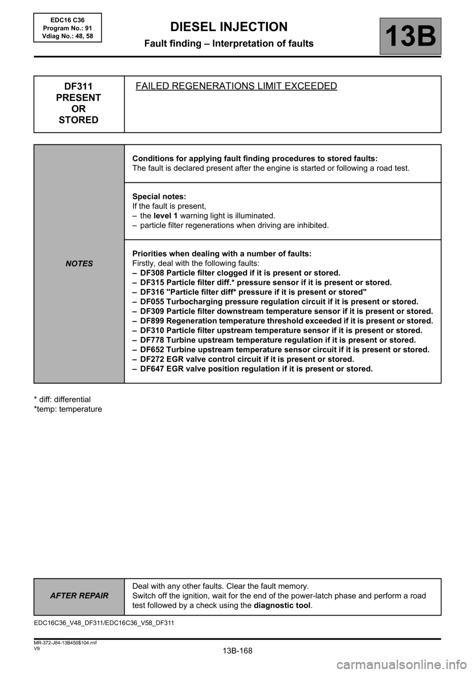
DF311
PRESENT
OR
STOREDFAILED REGENERATIONS LIMIT EXCEEDED
NOTESConditions for applying fault finding procedures to stored faults:
The fault is declared present after the engine is started or following a road test.
Special notes:
If the fault is present,
–the level 1 warning light is illuminated.
– particle filter regenerations when driving are inhibited.
Priorities when dealing with a number of faults:
Firstly, deal with the following faults:
– DF308 Particle filter clogged if it is present or stored.
– DF315 Particle filter diff.* pressure sensor if it is present or stored.
– DF316 "Particle filter diff* pressure if it is present or stored"
– DF055 Turbocharging pressure regulation circuit if it is present or stored.
– DF309 Particle filter downstream temperature sensor if it is present or stored.
– DF899 Regeneration temperature threshold exceeded if it is present or stored.
– DF310 Particle filter upstream temperature sensor if it is present or stored.
– DF778 Turbine upstream temperature regulation if it is present or stored.
– DF652 Turbine upstream temperature sensor circuit if it is present or stored.
– DF272 EGR valve control circuit if it is present or stored.
– DF647 EGR valve position regulation if it is present or stored.
EDC16C36_V48_DF311/EDC16C36_V58_DF311
DIESEL INJECTION
Fault finding – Interpretation of faults
EDC16 C36
Program No.: 91
Vdiag No.: 48, 58
Page 169 of 431

13B-169
AFTER REPAIRDeal with any other faults. Clear the fault memory.
Switch off the ignition until the end of the power-latch phase, and carry out a road test
followed by a check using the diagnostic tool.
V9 MR-372-J84-13B450$104.mif
DIESEL INJECTION
Fault finding – Interpretation of faults13B
DF311
CONTINUED
The fault appears after 11 failed regeneration attempts when driving.
Check that there are no leaks or blockages in the exhaust pipe,
Repair if necessary
– Carry out an After-Sales regeneration.
– Follow the procedure for command SC017 Particle filter regeneration (see Interpretation of commands).
– At the end of After-Sales regeneration, if the CLIP diagnostic tool indicates that you must replace the particle
filter, perform a oil change and replace the oil filter.
Explain to the customer the procedure for regeneration when driving to limit future garage repairs: see PART D in
the interpretation of DF312 Speed request.
If the fault is still present, contact the Techline.
EDC16 C36
Program No.: 91
Vdiag No.: 48, 58
Page 170 of 431

13B-170
AFTER REPAIRDeal with any other faults. Clear the fault memory.
Switch off the ignition until the end of the power-latch phase, and carry out a road test
followed by a check using the diagnostic tool.
V9 MR-372-J84-13B450$104.mif
DIESEL INJECTION
Fault finding – Interpretation of faults13B
* diff: differential
DF312
PRESENT
OR
STOREDSPEED REQUEST
NOTESConditions for applying fault finding procedures to stored faults:
The fault is declared present after the engine is started or following a road test.
Special notes:
If the fault is present:
– the special regenerate particle filter warning light is lit or a warning message is
displayed on the instrument panel.
– The vehicle needs to be driven specially to activate particle filter regeneration during
driving.
Priorities when dealing with a number of faults:
Firstly, deal with the following faults:
– DF308 Particle filter clogged if it is present or stored.
– DF311 Failed regenerations limit exceeded if it is present.
– DF315 Particle filter diff* pressure sensor if it is present or stored.
The fault appears after:
– 7 failed regeneration attempts when driving and the weight of soot in the particle filter is greater than
21 g.
– the weight of soot in the particle filter is greater than 58 g.
PART A:
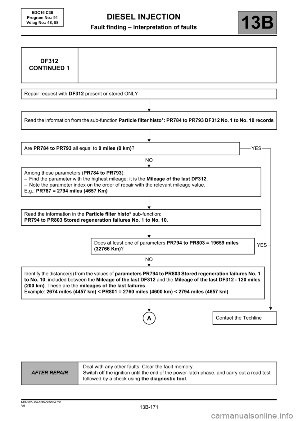
The flow chart on the following page can be used to analyse the driving profile and causes of the activation of this
fault.
EDC16C36_V48_DF312/EDC16C36_V58_DF312EDC16 C36
Program No.: 91
Vdiag No.: 48, 58
Page 171 of 431
13B-171
AFTER REPAIRDeal with any other faults. Clear the fault memory.
Switch off the ignition until the end of the power-latch phase, and carry out a road test
followed by a check using the diagnostic tool.
V9 MR-372-J84-13B450$104.mif
DIESEL INJECTION
Fault finding – Interpretation of faults13B
DF312
CONTINUED 1
Repair request with DF312 present or stored ONLY
Read the information from the sub-function Particle filter histo*: PR784 to PR793 DF312 No. 1 to No. 10 records
Are PR784 to PR793 all equal to 0 miles (0 km)?
Among these parameters (PR784 to PR793):
– Find the parameter with the highest mileage: it is the Mileage of the last DF312.
– Note the parameter index on the order of repair with the relevant mileage value.
E.g.: PR787 = 2794 miles (4657 Km)
Read the information in the Particle filter histo* sub-function:
PR794 to PR803 Stored regeneration failures No. 1 to No. 10.
Does at least one of parameters PR794 to PR803 = 19659 miles
(32766 Km)?
Identify the distance(s) from the values of parameters PR794 to PR803 Stored regeneration failures No. 1
to No. 10, included between the Mileage of the last DF312 and the Mileage of the last DF312 - 120 miles
(200 km). These are the mileages of the last failures.
Example: 2674 miles (4457 km) < PR801 = 2760 miles (4600 km) < 2794 miles (4657 km)
Contact the Techline
YES
YES
NO
NO
A
EDC16 C36
Program No.: 91
Vdiag No.: 48, 58