DF1 RENAULT SCENIC 2011 J95 / 3.G Engine And Peripherals EDC16C36 Owner's Guide
[x] Cancel search | Manufacturer: RENAULT, Model Year: 2011, Model line: SCENIC, Model: RENAULT SCENIC 2011 J95 / 3.GPages: 431, PDF Size: 2.03 MB
Page 205 of 431
13B-205V9 MR-372-J84-13B450$131.mif
13B
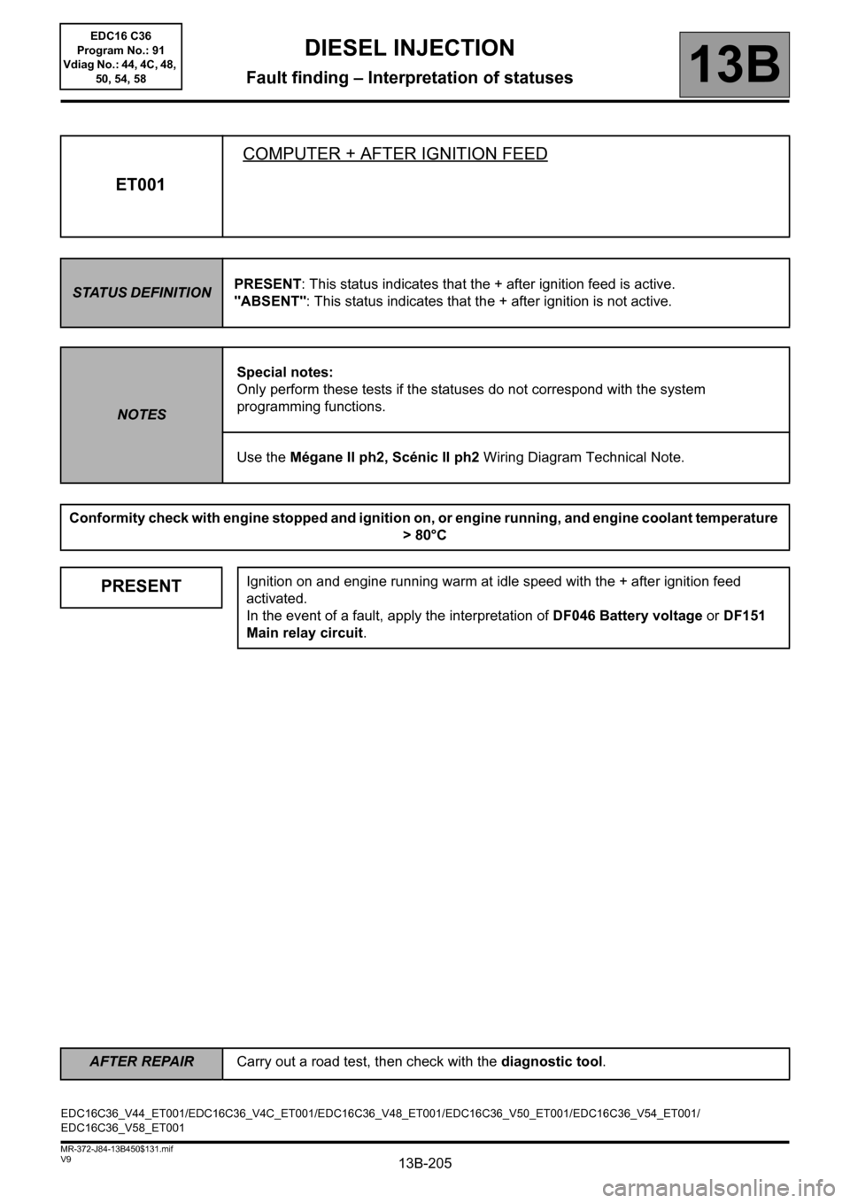
ET001COMPUTER + AFTER IGNITION FEED
STATUS DEFINITIONPRESENT: This status indicates that the + after ignition feed is active.
"ABSENT": This status indicates that the + after ignition is not active.
NOTESSpecial notes:
Only perform these tests if the statuses do not correspond with the system
programming functions.
Use the Mégane II ph2, Scénic II ph2 Wiring Diagram Technical Note.
Conformity check with engine stopped and ignition on, or engine running, and engine coolant temperature
> 80°C
PRESENTIgnition on and engine running warm at idle speed with the + after ignition feed
activated.
In the event of a fault, apply the interpretation of DF046 Battery voltage or DF151
Main relay circuit.
EDC16C36_V44_ET001/EDC16C36_V4C_ET001/EDC16C36_V48_ET001/EDC16C36_V50_ET001/EDC16C36_V54_ET001/
EDC16C36_V58_ET001
DIESEL INJECTION
Fault finding – Interpretation of statuses
AFTER REPAIRCarry out a road test, then check with the diagnostic tool.
EDC16 C36
Program No.: 91
Vdiag No.: 44, 4C, 48,
50, 54, 58
Page 235 of 431
13B-235V9 MR-372-J84-13B450$131.mif
DIESEL INJECTION
Fault finding – Interpretation of statuses13B
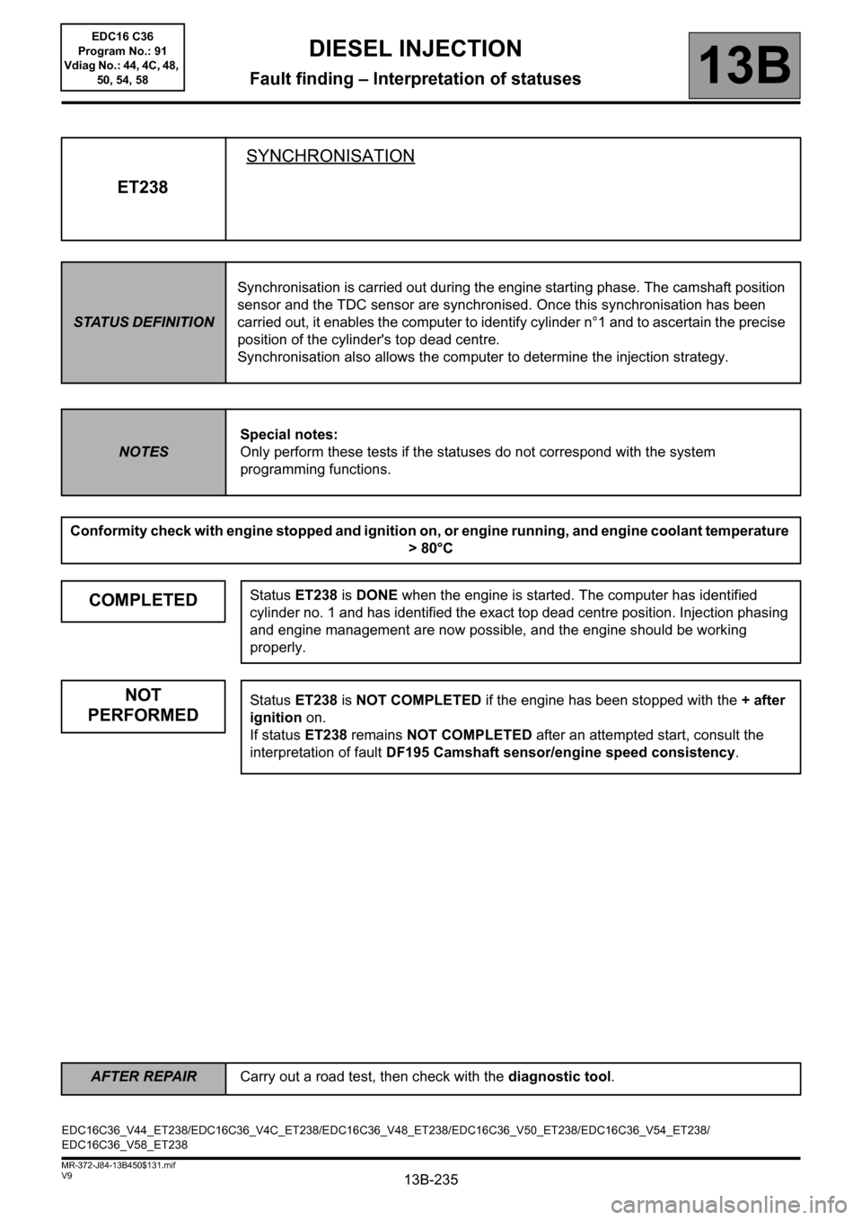
ET238SYNCHRONISATION
STATUS DEFINITIONSynchronisation is carried out during the engine starting phase. The camshaft position
sensor and the TDC sensor are synchronised. Once this synchronisation has been
carried out, it enables the computer to identify cylinder n°1 and to ascertain the precise
position of the cylinder's top dead centre.
Synchronisation also allows the computer to determine the injection strategy.
NOTESSpecial notes:
Only perform these tests if the statuses do not correspond with the system
programming functions.
Conformity check with engine stopped and ignition on, or engine running, and engine coolant temperature
> 80°C
COMPLETEDStatus ET238 is DONE when the engine is started. The computer has identified
cylinder no. 1 and has identified the exact top dead centre position. Injection phasing
and engine management are now possible, and the engine should be working
properly.
NOT
PERFORMEDStatus ET238 is NOT COMPLETED if the engine has been stopped with the + after
ignition on.
If status ET238 remains NOT COMPLETED after an attempted start, consult the
interpretation of fault DF195 Camshaft sensor/engine speed consistency.
EDC16C36_V44_ET238/EDC16C36_V4C_ET238/EDC16C36_V48_ET238/EDC16C36_V50_ET238/EDC16C36_V54_ET238/
EDC16C36_V58_ET238
AFTER REPAIRCarry out a road test, then check with the diagnostic tool.
EDC16 C36
Program No.: 91
Vdiag No.: 44, 4C, 48,
50, 54, 58
Page 272 of 431
13B-272
AFTER REPAIRCarry out a road test, then check with the diagnostic tool.
V9 MR-372-J84-13B450$151.mif
DIESEL INJECTION
Fault finding – Interpretation of parameters13B
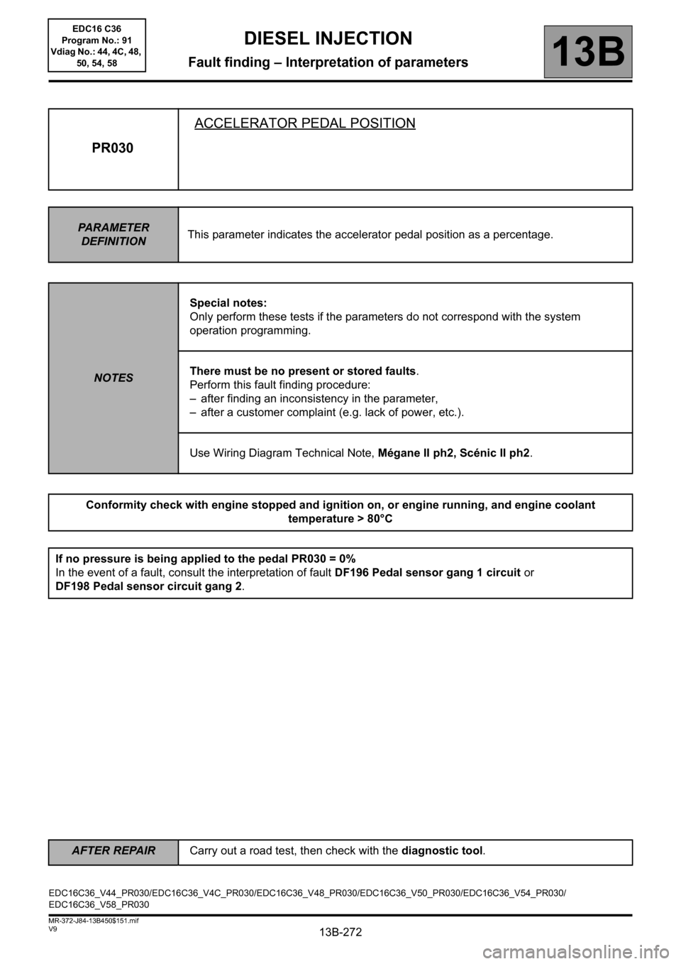
PR030ACCELERATOR PEDAL POSITION
PARAMETER
DEFINITIONThis parameter indicates the accelerator pedal position as a percentage.
NOTESSpecial notes:
Only perform these tests if the parameters do not correspond with the system
operation programming.
There must be no present or stored faults.
Perform this fault finding procedure:
– after finding an inconsistency in the parameter,
– after a customer complaint (e.g. lack of power, etc.).
Use Wiring Diagram Technical Note, Mégane II ph2, Scénic II ph2.
Conformity check with engine stopped and ignition on, or engine running, and engine coolant
temperature > 80°C
If no pressure is being applied to the pedal PR030 = 0%
In the event of a fault, consult the interpretation of fault DF196 Pedal sensor gang 1 circuit or
DF198 Pedal sensor circuit gang 2.
EDC16C36_V44_PR030/EDC16C36_V4C_PR030/EDC16C36_V48_PR030/EDC16C36_V50_PR030/EDC16C36_V54_PR030/
EDC16C36_V58_PR030EDC16 C36
Program No.: 91
Vdiag No.: 44, 4C, 48,
50, 54, 58
Page 285 of 431
13B-285
AFTER REPAIRCarry out a road test, then check with the diagnostic tool.
V9 MR-372-J84-13B450$151.mif
DIESEL INJECTION
Fault finding – Interpretation of parameters13B
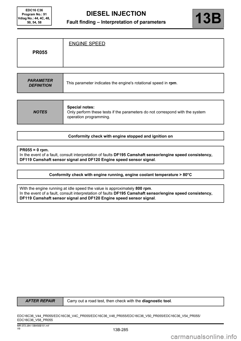
PR055ENGINE SPEED
PARAMETER
DEFINITIONThis parameter indicates the engine's rotational speed in rpm.
NOTESSpecial notes:
Only perform these tests if the parameters do not correspond with the system
operation programming.
Conformity check with engine stopped and ignition on
PR055 = 0 rpm.
In the event of a fault, consult interpretation of faults DF195 Camshaft sensor/engine speed consistency,
DF119 Camshaft sensor signal and DF120 Engine speed sensor signal.
Conformity check with engine running, engine coolant temperature > 80°C
With the engine running at idle speed the value is approximately 800 rpm.
In the event of a fault, consult interpretation of faults DF195 Camshaft sensor/engine speed consistency,
DF119 Camshaft sensor signal and DF120 Engine speed sensor signal.
EDC16C36_V44_PR055/EDC16C36_V4C_PR055/EDC16C36_V48_PR055/EDC16C36_V50_PR055/EDC16C36_V54_PR055/
EDC16C36_V58_PR055EDC16 C36
Program No.: 91
Vdiag No.: 44, 4C, 48,
50, 54, 58
Page 313 of 431
13B-313V9 MR-372-J84-13B450$152.mif
DIESEL INJECTION
Fault finding – Interpretation of parameters13B
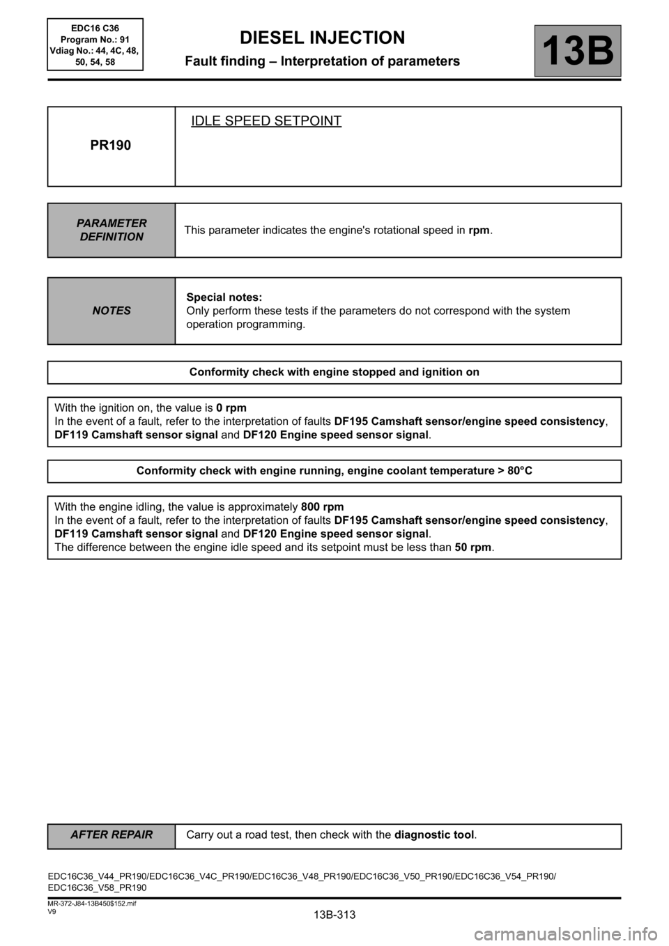
PR190IDLE SPEED SETPOINT
PARAMETER
DEFINITIONThis parameter indicates the engine's rotational speed in rpm.
NOTESSpecial notes:
Only perform these tests if the parameters do not correspond with the system
operation programming.
Conformity check with engine stopped and ignition on
With the ignition on, the value is 0 rpm
In the event of a fault, refer to the interpretation of faults DF195 Camshaft sensor/engine speed consistency,
DF119 Camshaft sensor signal and DF120 Engine speed sensor signal.
Conformity check with engine running, engine coolant temperature > 80°C
With the engine idling, the value is approximately 800 rpm
In the event of a fault, refer to the interpretation of faults DF195 Camshaft sensor/engine speed consistency,
DF119 Camshaft sensor signal and DF120 Engine speed sensor signal.
The difference between the engine idle speed and its setpoint must be less than 50 rpm.
EDC16C36_V44_PR190/EDC16C36_V4C_PR190/EDC16C36_V48_PR190/EDC16C36_V50_PR190/EDC16C36_V54_PR190/
EDC16C36_V58_PR190
AFTER REPAIRCarry out a road test, then check with the diagnostic tool.
EDC16 C36
Program No.: 91
Vdiag No.: 44, 4C, 48,
50, 54, 58
Page 366 of 431
13B-366
AFTER REPAIRRepeat the conformity check in the interpretation of statuses and parameters
V9 MR-372-J84-13B450$170.mif
DIESEL INJECTION
Fault finding – Interpretation of commands13B
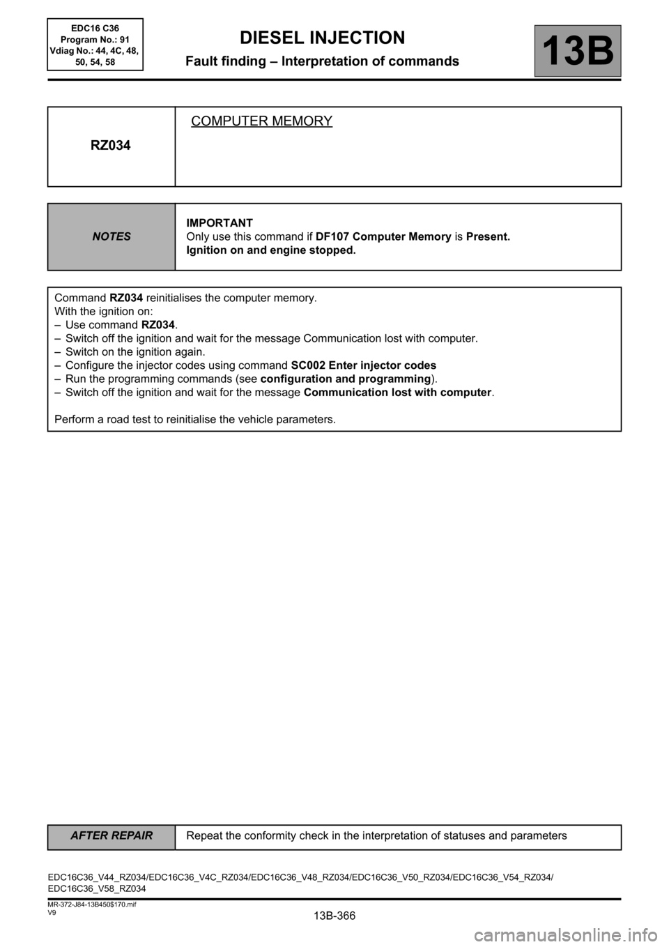
RZ034COMPUTER MEMORY
NOTESIMPORTANT
Only use this command if DF107 Computer Memory is Present.
Ignition on and engine stopped.
Command RZ034 reinitialises the computer memory.
With the ignition on:
– Use command RZ034.
– Switch off the ignition and wait for the message Communication lost with computer.
– Switch on the ignition again.
– Configure the injector codes using command SC002 Enter injector codes
– Run the programming commands (see configuration and programming).
– Switch off the ignition and wait for the message Communication lost with computer.
Perform a road test to reinitialise the vehicle parameters.
EDC16C36_V44_RZ034/EDC16C36_V4C_RZ034/EDC16C36_V48_RZ034/EDC16C36_V50_RZ034/EDC16C36_V54_RZ034/
EDC16C36_V58_RZ034EDC16 C36
Program No.: 91
Vdiag No.: 44, 4C, 48,
50, 54, 58
Page 383 of 431
13B-383
AFTER REPAIRCarry out a road test followed by a complete check with the diagnostic tool.
V9 MR-372-J84-13B450$190.mif
DIESEL INJECTION
Fault finding – Fault Finding Chart13B
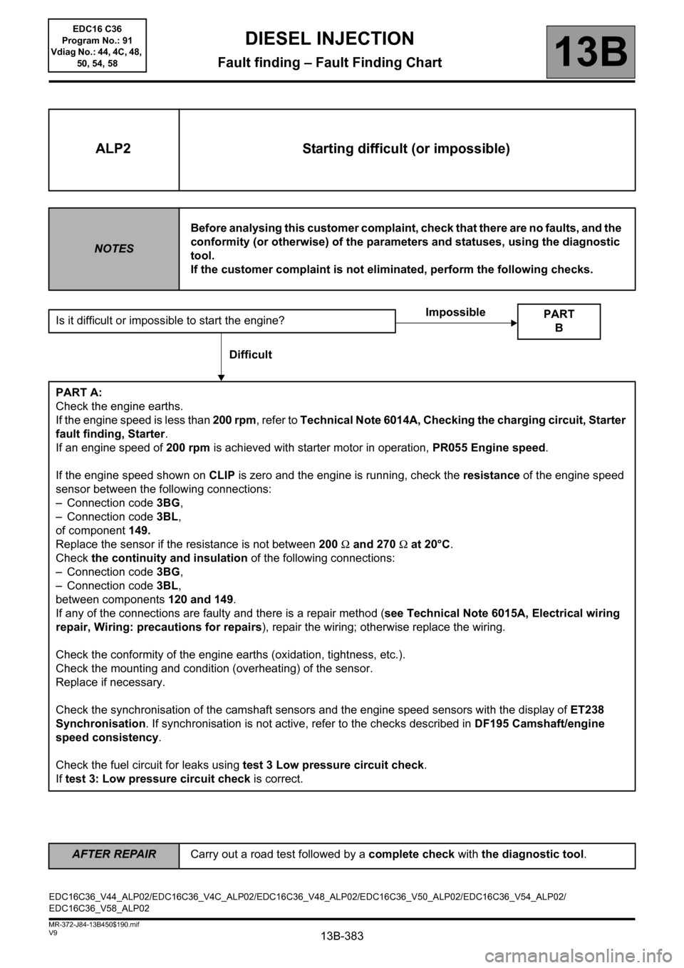
ALP2 Starting difficult (or impossible)
NOTESBefore analysing this customer complaint, check that there are no faults, and the
conformity (or otherwise) of the parameters and statuses, using the diagnostic
tool.
If the customer complaint is not eliminated, perform the following checks.
Is it difficult or impossible to start the engine?
PART A:
Check the engine earths.
If the engine speed is less than 200 rpm, refer to Technical Note 6014A, Checking the charging circuit, Starter
fault finding, Starter.
If an engine speed of 200 rpm is achieved with starter motor in operation, PR055 Engine speed.
If the engine speed shown on CLIP is zero and the engine is running, check the resistance of the engine speed
sensor between the following connections:
– Connection code 3BG,
– Connection code 3BL,
of component 149.
Replace the sensor if the resistance is not between 200 Ω and 270 Ω at 20°C.
Check the continuity and insulation of the following connections:
– Connection code 3BG,
– Connection code 3BL,
between components 120 and 149.
If any of the connections are faulty and there is a repair method (see Technical Note 6015A, Electrical wiring
repair, Wiring: precautions for repairs), repair the wiring; otherwise replace the wiring.
Check the conformity of the engine earths (oxidation, tightness, etc.).
Check the mounting and condition (overheating) of the sensor.
Replace if necessary.
Check the synchronisation of the camshaft sensors and the engine speed sensors with the display of ET238
Synchronisation. If synchronisation is not active, refer to the checks described in DF195 Camshaft/engine
speed consistency.
Check the fuel circuit for leaks using test 3 Low pressure circuit check.
If test 3: Low pressure circuit check is correct.
PART
B
Impossible
Difficult
EDC16C36_V44_ALP02/EDC16C36_V4C_ALP02/EDC16C36_V48_ALP02/EDC16C36_V50_ALP02/EDC16C36_V54_ALP02/
EDC16C36_V58_ALP02EDC16 C36
Program No.: 91
Vdiag No.: 44, 4C, 48,
50, 54, 58
Page 387 of 431
13B-387
AFTER REPAIRCarry out a road test followed by a complete check with the diagnostic tool.
V9 MR-372-J84-13B450$190.mif
DIESEL INJECTION
Fault finding – Fault Finding Chart13B
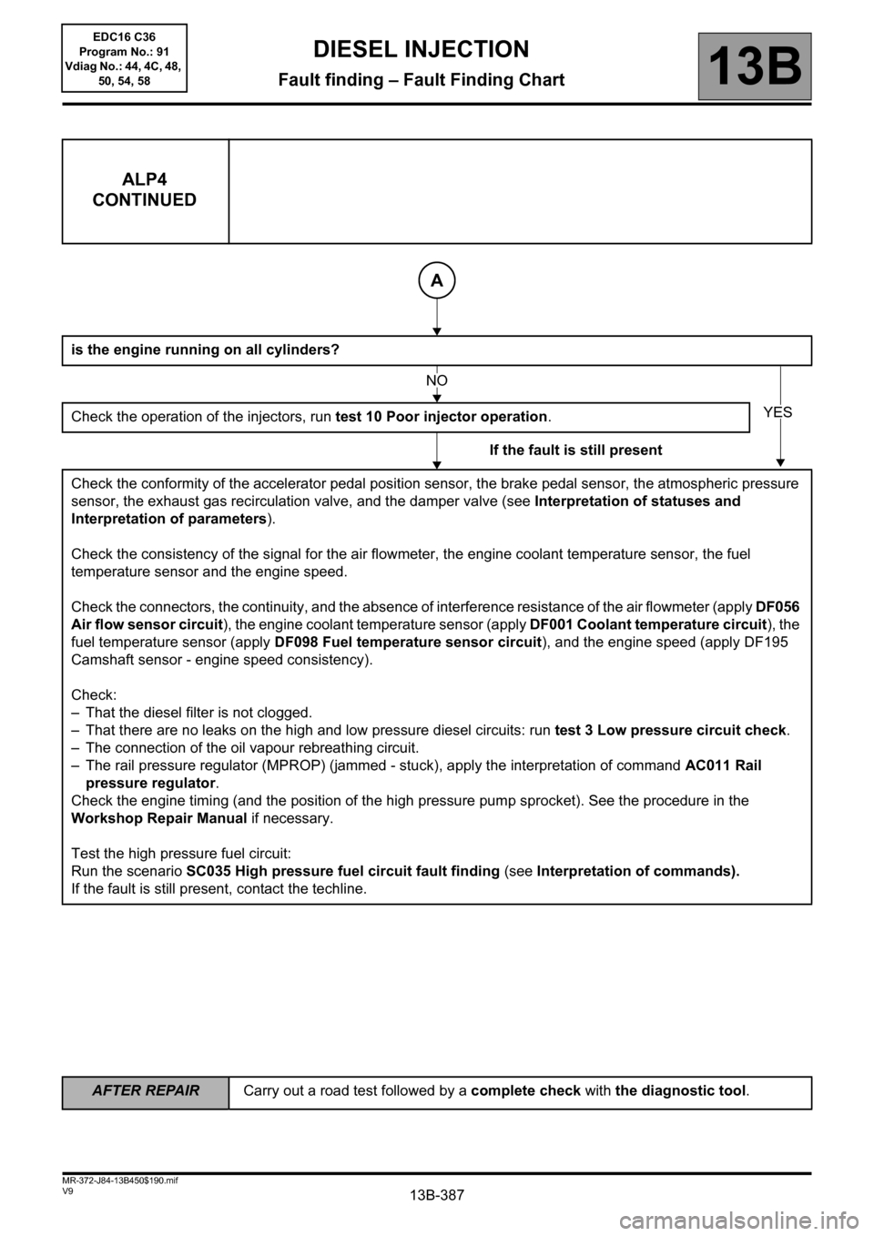
ALP4
CONTINUED
is the engine running on all cylinders?
Check the operation of the injectors, run test 10 Poor injector operation.
If the fault is still present
Check the conformity of the accelerator pedal position sensor, the brake pedal sensor, the atmospheric pressure
sensor, the exhaust gas recirculation valve, and the damper valve (see Interpretation of statuses and
Interpretation of parameters).
Check the consistency of the signal for the air flowmeter, the engine coolant temperature sensor, the fuel
temperature sensor and the engine speed.
Check the connectors, the continuity, and the absence of interference resistance of the air flowmeter (apply DF056
Air flow sensor circuit), the engine coolant temperature sensor (apply DF001 Coolant temperature circuit), the
fuel temperature sensor (apply DF098 Fuel temperature sensor circuit), and the engine speed (apply DF195
Camshaft sensor - engine speed consistency).
Check:
– That the diesel filter is not clogged.
– That there are no leaks on the high and low pressure diesel circuits: run test 3 Low pressure circuit check.
– The connection of the oil vapour rebreathing circuit.
– The rail pressure regulator (MPROP) (jammed - stuck), apply the interpretation of command AC011 Rail
pressure regulator.
Check the engine timing (and the position of the high pressure pump sprocket). See the procedure in the
Workshop Repair Manual if necessary.
Test the high pressure fuel circuit:
Run the scenario SC035 High pressure fuel circuit fault finding (see Interpretation of commands).
If the fault is still present, contact the techline.
A
NO
YES
EDC16 C36
Program No.: 91
Vdiag No.: 44, 4C, 48,
50, 54, 58