heating RENAULT SCENIC 2011 J95 / 3.G Engine And Peripherals EDC16C36 Owner's Guide
[x] Cancel search | Manufacturer: RENAULT, Model Year: 2011, Model line: SCENIC, Model: RENAULT SCENIC 2011 J95 / 3.GPages: 431, PDF Size: 2.03 MB
Page 350 of 431

13B-350V9 MR-372-J84-13B450$160.mif
13B
EDC16 C36
Program No.: 91
Vdiag No.: 44, 4C, 48,
50, 54, 58
Tool
commandDiagnostic tool title comments
SC001Write saved data See Interpretation of commands.
SC002Enter injector codes See Interpretation of commands.
SC003Save computer data See Interpretation of commands.
SC017Particle filter regeneration See Interpretation of commands.
SC031Operational fault finding of cylinders See Interpretation of commands.
SC035High pressure fuel circuit fault finding See Interpretation of commands.
SC036Reinitialise programming See Interpretation of commands.
RZ001Fault memory See Interpretation of commands.
RZ005Programming See Interpretation of commands.
RZ034Computer memory See Interpretation of commands.
LC009Air conditioning See configuration and programming.
LC056Heating elements See configuration and programming.
LC065Water in diesel fuel sensor See configuration and programming.
LC120Cruise control See configuration and programming.
LC121Speed limiter See configuration and programming.
AC004Turbocharging solenoid valve See Interpretation of commands.
AC011Rail pressure regulator See Interpretation of commands.
AC012Damper valve See Interpretation of commands.
AC037Preheating relay See Interpretation of commands.
AC038Low speed GMV relay See Interpretation of commands.
AC039High speed GMV relay See Interpretation of commands.
AC103EGR by-pass See Interpretation of commands.
AC231Richness ratio sensor heating See Interpretation of commands.
VP010Write VIN See Interpretation of commands.
VP036Fuel supply inhibited See
Interpretation of commands.
VP037Lift fuel supply inhibition See Interpretation of commands.
DIESEL INJECTION
Fault finding – Command summary table
Page 356 of 431

13B-356
AFTER REPAIRRepeat the conformity check in the interpretation of statuses and parameters
V9 MR-372-J84-13B450$170.mif
DIESEL INJECTION
Fault finding – Interpretation of commands13B
SC017
CONTINUED 1
DESCRIPTION OF THE PROCESS
Particle filter regeneration takes place in 3 stages (values given as a guide only):
–Heating phase: the engine speed is fixed or fluctuating around 2000 rpm.
This phase lasts between 8 and 14 minutes, until the coolant temperature exceeds 70°C.
–Regeneration phase: the speed is fixed or varies around 2000 rpm. Engine injection is retarded. The exhaust
fumes rise in temperature and burn the soot retained in the particle filter. Then the combustion of the soot stored
in the particle filter causes the particle filter upstream temperature to increase, possibly reaching 600°C
depending on the amount of soot in the particle filter. This phase lasts 28 minutes.
–Cooling phase: the engine speed decreases to 1250 rpm then increases to 1750 rpm.
Engine injection returns to normal and the exhaust gases cool the particle filter.
This phase lasts 3 minutes.
The procedure lasts at least 40 minutes, and varies depending on the time taken to reach a coolant temperature
of 70°C.
VALIDATING THE REGENERATION PROCESS:
At the end of regeneration, a message appears to announce whether the regeneration was successful:
●Particle filter regeneration finished:
Consult PR1012 Weight of soot after regeneration. If PR1012 is less than 15 g, the particle filter regeneration
completed correctly. If PR1012 is greater than 15 g, a second particle filter regeneration must be performed using
the command in the diagnostic tool and choose command SC017.
EDC16 C36
Program No.: 91
Vdiag No.: 48, 50, 58
Page 372 of 431

13B-372
AFTER REPAIRRepeat the conformity check in the interpretation of statuses and parameters
V9 MR-372-J84-13B450$170.mif
DIESEL INJECTION
Fault finding – Interpretation of commands13B
AC037PREHEATING RELAY
NOTESThis command is only run if fault DF025 Preheating unit diagnostic connection or
DF017 Preheating unit control circuit is present or stored and if no other fault is
present.
Ignition on and engine stopped.
Use Wiring Diagram Technical Note, Mégane II ph2, Scénic II ph2.
Before applying the following fault finding procedure, check that the battery voltage is not below 12 V.
Otherwise, recharge the battery.
Check the connections on the preheating unit, heater plugs and injection computer.
If there is a repair method (see Technical Note 6015A, Repairing electrical wiring, Wiring: Precautions for
repair), repair the wiring, otherwise replace it.
Measure the resistance of the heater plugs. If this resistance is > 2 Ω, replace the defective plug(s).
Check the continuity and the absence of interference resistance on the following connections:
– Connection code 37AA between components257 and 681.
– Connection code 37AB between components 257 and 682.
– Connection code 37AC between components 257 and 683.
– Connection code 37AZ between components 257 and 680.
Check the condition of fuse FM12 (70 A) of the preheating unit supply. Replace it if necessary.
Then check for +12 V on connection BP35 of component 257.
Check the continuity, insulation, and the absence of interference resistance of the following connections:
– Connection code 3FF,
– Connection code 3FY,
Between components 257 and 120.
If the fault is still present, replace the pre-postheating unit.
EDC16C36_V44_AC037/EDC16C36_V4C_AC037/EDC16C36_V48_AC037/EDC16C36_V50_AC037/EDC16C36_V54_AC037/
EDC16C36_V58_AC037EDC16 C36
Program No.: 91
Vdiag No.: 44, 4C, 48,
50, 54, 58
Page 383 of 431

13B-383
AFTER REPAIRCarry out a road test followed by a complete check with the diagnostic tool.
V9 MR-372-J84-13B450$190.mif
DIESEL INJECTION
Fault finding – Fault Finding Chart13B
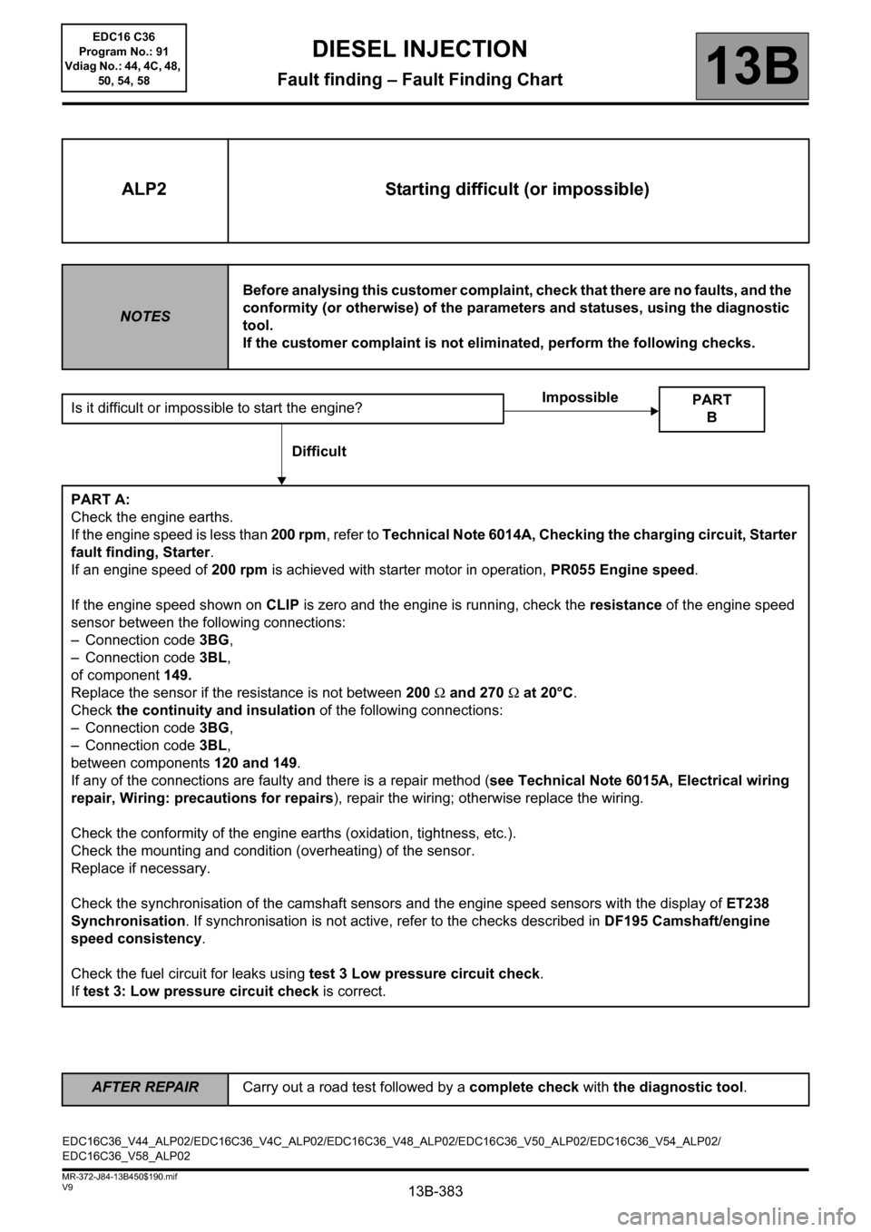
ALP2 Starting difficult (or impossible)
NOTESBefore analysing this customer complaint, check that there are no faults, and the
conformity (or otherwise) of the parameters and statuses, using the diagnostic
tool.
If the customer complaint is not eliminated, perform the following checks.
Is it difficult or impossible to start the engine?
PART A:
Check the engine earths.
If the engine speed is less than 200 rpm, refer to Technical Note 6014A, Checking the charging circuit, Starter
fault finding, Starter.
If an engine speed of 200 rpm is achieved with starter motor in operation, PR055 Engine speed.
If the engine speed shown on CLIP is zero and the engine is running, check the resistance of the engine speed
sensor between the following connections:
– Connection code 3BG,
– Connection code 3BL,
of component 149.
Replace the sensor if the resistance is not between 200 Ω and 270 Ω at 20°C.
Check the continuity and insulation of the following connections:
– Connection code 3BG,
– Connection code 3BL,
between components 120 and 149.
If any of the connections are faulty and there is a repair method (see Technical Note 6015A, Electrical wiring
repair, Wiring: precautions for repairs), repair the wiring; otherwise replace the wiring.
Check the conformity of the engine earths (oxidation, tightness, etc.).
Check the mounting and condition (overheating) of the sensor.
Replace if necessary.
Check the synchronisation of the camshaft sensors and the engine speed sensors with the display of ET238
Synchronisation. If synchronisation is not active, refer to the checks described in DF195 Camshaft/engine
speed consistency.
Check the fuel circuit for leaks using test 3 Low pressure circuit check.
If test 3: Low pressure circuit check is correct.
PART
B
Impossible
Difficult
EDC16C36_V44_ALP02/EDC16C36_V4C_ALP02/EDC16C36_V48_ALP02/EDC16C36_V50_ALP02/EDC16C36_V54_ALP02/
EDC16C36_V58_ALP02EDC16 C36
Program No.: 91
Vdiag No.: 44, 4C, 48,
50, 54, 58
Page 384 of 431

13B-384
AFTER REPAIRCarry out a road test followed by a complete check with the diagnostic tool.
V9 MR-372-J84-13B450$190.mif
DIESEL INJECTION
Fault finding – Fault Finding Chart13B
ALP2
CONTINUED 1
Test the high pressure fuel circuit:
Run the scenario SC035 High pressure fuel circuit fault finding (see Interpretation of commands).
Check that the heater plugs are actuated using the AC037 Preheating relay command.
Check the tightness and the condition of the inlet circuit: run test 4: Turbocharged air inlet circuit check and
follow the procedure.
Check that the exhaust is not blocked, run test 1 Exhaust system check and follow the procedure.
Check the consistency of the signal from the engine coolant temperature sensor.
Check the operation of the rail pressure regulator (DRV) using command AC011 Rail pressure regulator.
Check the timing setting.
End of part A
EDC16 C36
Program No.: 91
Vdiag No.: 44, 4C, 48,
50, 54, 58
Page 386 of 431

13B-386
AFTER REPAIRCarry out a road test followed by a complete check with the diagnostic tool.
V9 MR-372-J84-13B450$190.mif
DIESEL INJECTION
Fault finding – Fault Finding Chart13B
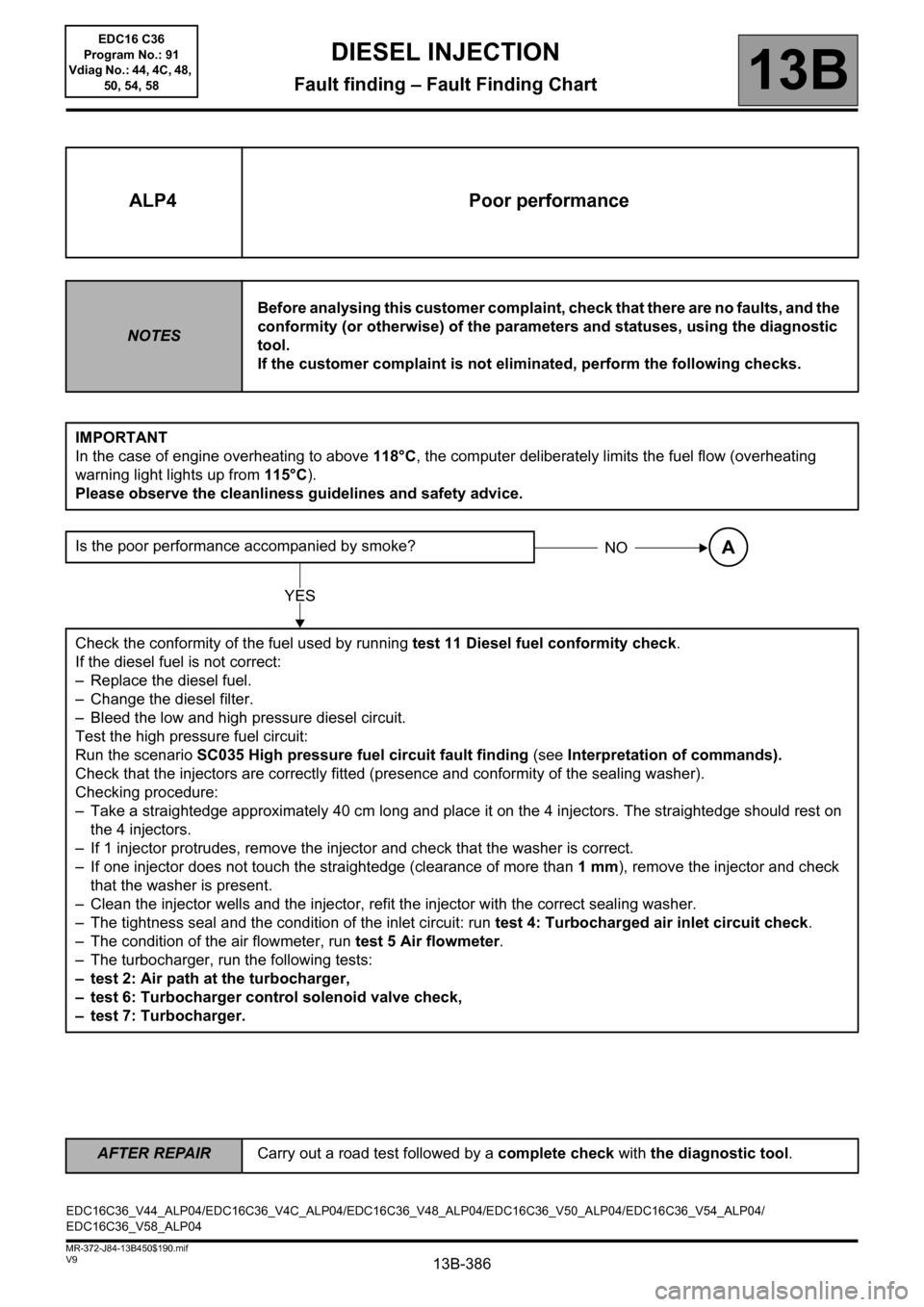
ALP4 Poor performance
NOTESBefore analysing this customer complaint, check that there are no faults, and the
conformity (or otherwise) of the parameters and statuses, using the diagnostic
tool.
If the customer complaint is not eliminated, perform the following checks.
IMPORTANT
In the case of engine overheating to above 118°C, the computer deliberately limits the fuel flow (overheating
warning light lights up from 115°C).
Please observe the cleanliness guidelines and safety advice.
Is the poor performance accompanied by smoke?
Check the conformity of the fuel used by running test 11 Diesel fuel conformity check.
If the diesel fuel is not correct:
– Replace the diesel fuel.
– Change the diesel filter.
– Bleed the low and high pressure diesel circuit.
Test the high pressure fuel circuit:
Run the scenario SC035 High pressure fuel circuit fault finding (see Interpretation of commands).
Check that the injectors are correctly fitted (presence and conformity of the sealing washer).
Checking procedure:
– Take a straightedge approximately 40 cm long and place it on the 4 injectors. The straightedge should rest on
the 4 injectors.
– If 1 injector protrudes, remove the injector and check that the washer is correct.
– If one injector does not touch the straightedge (clearance of more than 1 mm), remove the injector and check
that the washer is present.
– Clean the injector wells and the injector, refit the injector with the correct sealing washer.
– The tightness seal and the condition of the inlet circuit: run test 4: Turbocharged air inlet circuit check.
– The condition of the air flowmeter, run test 5 Air flowmeter.
– The turbocharger, run the following tests:
– test 2: Air path at the turbocharger,
– test 6: Turbocharger control solenoid valve check,
– test 7: Turbocharger.
NOA
YES
EDC16C36_V44_ALP04/EDC16C36_V4C_ALP04/EDC16C36_V48_ALP04/EDC16C36_V50_ALP04/EDC16C36_V54_ALP04/
EDC16C36_V58_ALP04EDC16 C36
Program No.: 91
Vdiag No.: 44, 4C, 48,
50, 54, 58
Page 388 of 431

13B-388
AFTER REPAIRCarry out a road test followed by a complete check with the diagnostic tool.
V9 MR-372-J84-13B450$190.mif
DIESEL INJECTION
Fault finding – Fault Finding Chart13B
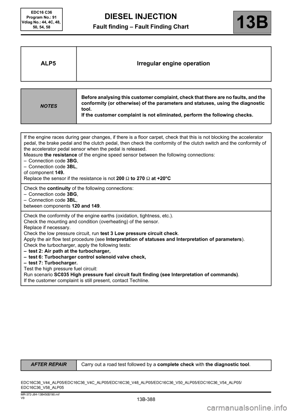
ALP5 Irregular engine operation
NOTESBefore analysing this customer complaint, check that there are no faults, and the
conformity (or otherwise) of the parameters and statuses, using the diagnostic
tool.
If the customer complaint is not eliminated, perform the following checks.
If the engine races during gear changes, if there is a floor carpet, check that this is not blocking the accelerator
pedal, the brake pedal and the clutch pedal, then check the conformity of the clutch switch and the conformity of
the accelerator pedal sensor when the pedal is released.
Measure the resistance of the engine speed sensor between the following connections:
– Connection code 3BG,
– Connection code 3BL,
of component 149.
Replace the sensor if the resistance is not 200 Ω to 270 Ω at +20°C
Check the continuity of the following connections:
– Connection code 3BG,
– Connection code 3BL,
between components120 and 149.
Check the conformity of the engine earths (oxidation, tightness, etc.).
Check the mounting and condition (overheating) of the sensor.
Replace if necessary.
Check the low pressure circuit, run test 3 Low pressure circuit check.
Apply the air flow test procedure (see Interpretation of statuses and Interpretation of parameters).
Check the turbocharger, apply the following tests:
– test 2: Air path at the turbocharger,
– test 6: Turbocharger control solenoid valve check,
– test 7: Turbocharger.
Test the high pressure fuel circuit:
Run scenario SC035 High pressure fuel circuit fault finding (see Interpretation of commands).
If the customer complaint is still present, contact Techline.
EDC16C36_V44_ALP05/EDC16C36_V4C_ALP05/EDC16C36_V48_ALP05/EDC16C36_V50_ALP05/EDC16C36_V54_ALP05/
EDC16C36_V58_ALP05EDC16 C36
Program No.: 91
Vdiag No.: 44, 4C, 48,
50, 54, 58