oil filter RENAULT SCENIC 2011 J95 / 3.G Engine And Peripherals EDC16C36 Workshop Manual
[x] Cancel search | Manufacturer: RENAULT, Model Year: 2011, Model line: SCENIC, Model: RENAULT SCENIC 2011 J95 / 3.GPages: 431, PDF Size: 2.03 MB
Page 8 of 431

13B-8V9 MR-372-J84-13B450$020.mif
13B
EDC16 C36
Program No.: 91
Vdiag No.: 44, 4C, 48,
50, 54, 58
1. HAZARDS ASSOCIATED WITH CONTAMINATION
The high pressure direct injection system is highly sensitive to contamination. The risks caused by the introduction of
contamination are:
– damage to or destruction of the high pressure injection system,
– a component seizing up,
– a component losing its sealing.
All After-Sales operations must be performed under very clean conditions. This means that no impurities (particles
a few microns in size) should have penetrated the system during dismantling.
The cleanliness guidelines must be applied from the filter through to the injectors.
What are the sources of contamination?
– metal or plastic swarf,
– paint,
–fibres:
– from cardboard,
– from brushes,
– from paper,
– from clothing,
– from cloths,
– foreign bodies such as hair,
– the ambient atmosphere,
–etc.
2. INSTRUCTIONS TO BE FOLLOWED PRIOR TO ALL OPERATIONS
Check that you have plugs for the unions to be opened (set of plugs available from the Parts Department). The plugs
are single-use only. After use, they must be discarded (once used they are soiled and cleaning is not sufficient to
make them reusable). Unused plugs must be discarded.IMPORTANT
Cleaning the engine using a high pressure washer is prohibited because of the risk of damaging connections.
In addition, moisture may collect in the connectors and create faults in the electrical connections.
IMPORTANT
Before carrying out any work on the high pressure injection system, protect:
– the accessories and timing belts,
– the electrical accessories, (starter, alternator, electric power-assisted steering pump),
– the flywheel surface, to prevent any diesel from running onto the clutch friction plate.
DIESEL INJECTION
Fault finding – Cleanliness guidelines
Page 22 of 431

13B-22V9 MR-372-J84-13B450$050.mif
DIESEL INJECTION
Fault finding – Features13B
EDC16 C36
Program No.: 91
Vdiag No.: 44, 4C, 48,
50, 54, 58
If all the criteria are met, the computer enters regeneration mode. The injection programming is adjusted in order to
raise the target exhaust gas temperature between 550 and 650°C.
This temperature allows the particles accumulated in the filter to be partially or completely burnt (regenerated).
Regeneration efficiency depends on the particle filter inlet temperature and the time spent in regeneration mode.
Regeneration can be carried out automatically when driving if the weight of soot is less than 70 g and if the number
of regeneration attempts when driving is less than 11 (only for Vdiag 48).
If the weight of soot is greater than 70 g, the user will have to request an After-sales regeneration.
This regeneration is carried out in the workshop. Always follow the instructions written in the interpretation of
commands (SC017 Particle filter regeneration) to perform regeneration in complete safety.
After an After-sales regeneration, always reconfigure certain parameters in the computer using command SC036
Reinitialise programming (see "interpretation of commands").
Warning light management:
Instrument panel display
The computer displays certain information on the instrument panel relating to engine operation. This involves six
functions:
– the pre-postheating warning light,
– the coolant temperature warning message,
– the level 1 fault warning light (non-critical fault),
– the level 2 fault warning light (emergency stop),
– the OBD warning light (European On Board Diagnostic),
– the particle filter specific warning light (F9Q816 engine only).
These six functions are represented by 6 warning lights and/or messages displayed by the on-board computer.
In addition, certain warning lights are, when lit, accompanied by a spoken message on vehicles fitted with a voice
synthesiser (refer to the driver's handbook).
A 3 second visual inspection (automatic test procedure managed by the instrument panel) is carried out by the
injection computer when the ignition is switched on.IMPORTANT
The particle filter must be replaced after a period of time which largely depends on the grade of engine oil used -
this information is in the driver's handbook.
After replacing it, always reconfigure certain parameters in the computer using command SC036 Reinitialise
programming (see "interpretation of commands").
Page 29 of 431

13B-29V9 MR-372-J84-13B450$080.mif
13B
EDC16 C36
Program No.: 91
Vdiag No.: 44, 4C, 48,
50, 54, 58
COMPUTER REPLACEMENT OR REPROGRAMMING
Two operations must be performed when replacing or reprogramming the computer:
SC003 Save computer data and SC001 Enter saved data.
–Run SC003 Save computer data before replacing or reprogramming the computer. This enables certain data
to be saved in the diagnostic tool so that the new computer* can be reconfigured like the old one. The saved data
are: injector codes, EGR programming, vehicle options.
–Run SC001 Enter saved data after replacing or reprogramming the computer. This enables the data (saved by
the command SC003 Save computer data) to be rewritten in the new computer*.
If you cannot establish dialogue with the computer being replaced: you will not be able to save anything.
After replacing the computer, write the IMA codes of each injector manually using command SC002 Enter injector
codes by reading the code on each injector (see Replacing the injectors).
Only on F9Q816 engines:
– Enter the data specific to particle filter operation by running SC036 Reinitialise programming and selecting after
replacing injection computer with no save option.
Exhaust gas recirculation valve data is programmed automatically the 1st time the new computer is turned on*.
* New computer or reprogrammed computer.
Specific to the cruise control/speed limiter operation to be carried out before reprogramming of the computer:
Before reprogramming the injection computer, move the main Cruise control/Speed limiter switch to the rest
position. The information about the cruise control or the speed limiter displayed on the instrument panel
disappears.
Otherwise, if the main switch remains in the cruise control or speed limiter position during and after reprogramming,
the Cruise control/Speed limiter function will not be operational.
The procedure for resetting the function is as follows:
– Vehicle ignition on.
– Position the main switch in rest position (the computer then detects the rest position).
– Position the switch in Cruise control position to activate the Cruise control function.
– Position the switch in Speed limiter position to activate the Speed limiter function. IMPORTANT
– Switch on the diagnostic tool (mains or cigarette lighter supply).
– Connect a battery charger.
– Cut off all the electrical consumers (lights, interior lighting, air conditioning, radio CD, etc.).
– Wait for the engine to cool (engine coolant temperature < 60° and air temperature < 50°).
– During (re)programming, the instrument panel screen displays "Oil pressure fault".
Ignore this message and do not take any action in connection with it.
DIESEL INJECTION
Fault finding – Replacement of components
Page 39 of 431

13B-39V9 MR-372-J84-13B450$090.mif
DIESEL INJECTION
Fault finding – Fault summary table13B
EDC16 C36
Program No.: 91
Vdiag No.: 44, 4C, 48,
50, 54, 58
* regener: regenerationFaultDTC code in
hexadecimalLevel 1 fault
warning light
(orange
SERVICE
warning light)Level 2 fault
warning light
(red STOP
warning light)No fault
warning
light litOBD
warning
light lit
DF890 Movement during
particle filter regener.* 297 - - X -
DF891 Group 1 injectors feed 2146 - 1.DEF/2.DEF - -
DF892 Group 2 injectors feed 2149 - 1.DEF/2.DEF - -
DF899 Regeneration
temperature threshold limit
exceeded 3031 1.DEF
DF953 Particle filter absent 2002 - - X
DF967 Richness ratio sensor
circuit130 - -CC.0/CC.1/
CO/1.DEF/
2.DEF/
3.DEF-
DF970 Richness ratio sensor
heater circuit135 - -CC.0/CC.1/
CO/1.DEF/
2.DEF/
3.DEF-
DF980 Richness ratio sensor
function2A00 - -1.DEF/
2.DEF/
3.DEF-
DF1020 Engine oil dilution 253F 1.DEF - - -
Page 116 of 431

13B-116V9 MR-372-J84-13B450$102.mif
DIESEL INJECTION
Fault finding – Interpretation of faults13B
DF107
CONTINUED
Only for F9Q816:
If the vehicle is not new (mileage greater than 10 km):
Check that there are no leaks or blockages in the exhaust pipe,
Repair if necessary
– Do an after-sales regeneration using the control SC017 Particle filter regeneration.
– Perform an oil change (see MR 364 (Mégane II) or MR 370 (Scénic II), Mechanical, 10A Engine and
peripherals, Engine oil: Draining – Filling).
If the fault is still present, contact the Techline.
Page 169 of 431
13B-169
AFTER REPAIRDeal with any other faults. Clear the fault memory.
Switch off the ignition until the end of the power-latch phase, and carry out a road test
followed by a check using the diagnostic tool.
V9 MR-372-J84-13B450$104.mif
DIESEL INJECTION
Fault finding – Interpretation of faults13B
DF311
CONTINUED
The fault appears after 11 failed regeneration attempts when driving.
Check that there are no leaks or blockages in the exhaust pipe,
Repair if necessary
– Carry out an After-Sales regeneration.
– Follow the procedure for command SC017 Particle filter regeneration (see Interpretation of commands).
– At the end of After-Sales regeneration, if the CLIP diagnostic tool indicates that you must replace the particle
filter, perform a oil change and replace the oil filter.
Explain to the customer the procedure for regeneration when driving to limit future garage repairs: see PART D in
the interpretation of DF312 Speed request.
If the fault is still present, contact the Techline.
EDC16 C36
Program No.: 91
Vdiag No.: 48, 58
Page 201 of 431
13B-201
AFTER REPAIRDeal with any other faults. Clear the fault memory.
Switch off the ignition until the end of the power-latch phase, and carry out a road test
followed by a check using the diagnostic tool.
V9 MR-372-J84-13B450$104.mif
DIESEL INJECTION
Fault finding – Interpretation of faults13B
*ADAC: Trip Computer
DF1020
PRESENT
OR
STOREDENGINE OIL DILUTION
1. DEF: Above maximum threshold
NOTESConditions for applying the fault finding procedure to a stored fault:
The fault is declared present after:
– the engine is started.
– a road test.
Special notes:
If the fault is present:
– particle filter regeneration is inhibited.
Use bornier Elé. 1681 for any operations on the injection computer connectors.
Use Wiring Diagram Technical Note, Mégane II ph2, Scénic II ph2.
Note:
This fault is activated in case of considerable oil dilution due to a significant number of particle filter regenerations.
Carry out the following:
– An oil change (see MR 364 (Mégane II) or MR 370 (Scénic II), Mechanical, 10A Engine and peripherals,
Engine oil: Draining – Filling),
– reset the oil wear meter,
– clear the faults.
Reset the oil wear meter after the oil change:
It will be necessary to reinitialise the display of the trip computer.
With the ignition on:
– hold down the TC* button for 5 s.
Re-initialisation has worked when the on-board computer no longer displays the key.
If this is not the case, restart the procedure.
Specific case:
If an oil change is performed before the oil service interval warning is exceeded, reinitialise the display.
EDC16C36_V50_DF1020/EDC16C36_V58_DF1020EDC16 C36
Program No.: 91
Vdiag No.: 50, 58
Page 309 of 431
13B-309V9 MR-372-J84-13B450$152.mif
DIESEL INJECTION
Fault finding – Interpretation of parameters13B
PR132
CONTINUED
Sensor electrical conformity
Test the air inlet circuit (from the air filter inlet to the inlet manifold,
apply test 4 Turbocharged air inlet circuit check):
– air filter unit inlet not blocked and filter not clogged,
–visual inspection only, run test 4 of ALP2: Starting fault or starting impossible,
– oil vapour recirculation circuit connection conformity.
–absence of leaks or blockages in the low and high pressure air circuits: pipes, presence and tightness of the
mounting clips, mounting of the turbocharger pressure sensor, intercooler, etc.,
– check that the damper valve is not jammed closed.
Carry out the necessary repairs.
Check the electrical conformity of the air flowmeter:
Check the + 5 V feed to the air flowmeter.
– connection 3KJ of component 799.
Check the +12 V after relay feed to the air flowmeter.
– connection 3FB of component 799.
Check for continuity and absence of interference resistance of the following connections:
– connection code3DV,
– connection code3DW,
between components 120 and 799.
With the flowmeter connected, the vehicle ignition on and engine stopped:
Check the voltage between connections 3DW and 3DV of component 799.
– If the voltage is not approximately 0.6 V ± 0.1 V, replace the air flowmeter.
AFTER REPAIRCarry out a road test, then check with the diagnostic tool.
EDC16 C36
Program No.: 91
Vdiag No.: 44, 4C, 48,
50, 54, 58
Page 349 of 431
13B-349V9 MR-372-J84-13B450$152.mif
DIESEL INJECTION
Fault finding – Interpretation of parameters13B
PR1012WEIGHT OF SOOT AFTER REGENERATION
PARAMETER
DEFINITIONThis parameter indicates the weight of soot, in g, in the particle filter after a
regeneration.
NOTESConsult this parameter after using SC017 Particle filter regeneration.
Conformity check: Engine stopped and the ignition on, or the engine running and the engine coolant
temperature > 80°C without electrical consumers.
If PR1012 is less than 15 g, the particle filter regeneration completed correctly.
If PR1012 is greater than 15 g, it is necessary to perform a second particle filter regeneration using command
SC017 Particle filter regeneration (see interpretation of commands).
IMPORTANT:
Before performing a second After-Sales regeneration of the particle filter, the engine must be allowed to cool down
for 2 hours with the bonnet open.
Do not carry out the usual engine oil change before a second After-Sales regeneration (see SC017 Particle filter
regeneration).
EDC16C36_V48_PR1012/EDC16C36_V50_PR1012/EDC16C36_V58_PR1012EDC16 C36
Program No.: 91
Vdiag No.: 48, 50, 58
Page 355 of 431
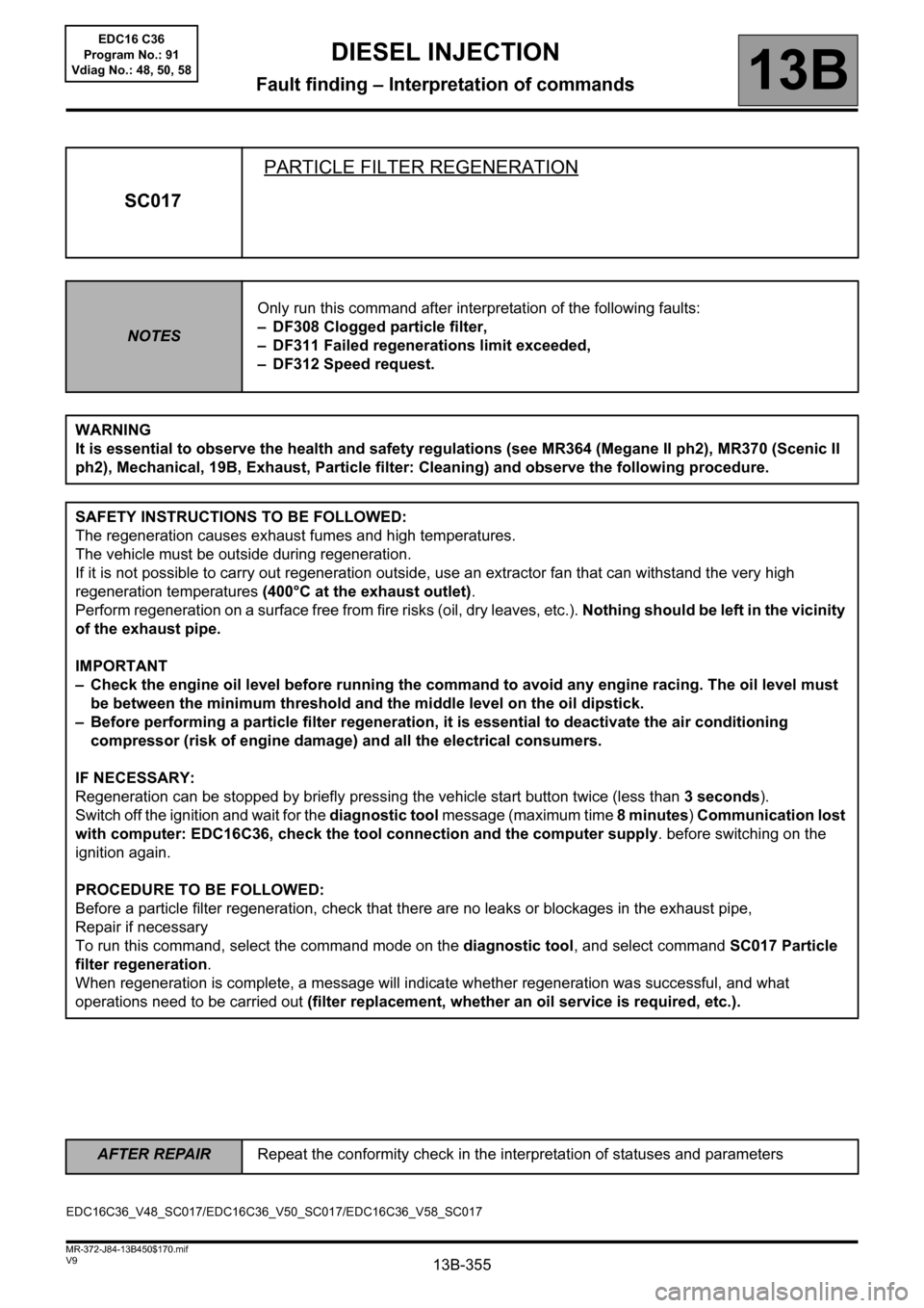
13B-355
AFTER REPAIRRepeat the conformity check in the interpretation of statuses and parameters
V9 MR-372-J84-13B450$170.mif
DIESEL INJECTION
Fault finding – Interpretation of commands13B
SC017PARTICLE FILTER REGENERATION
NOTESOnly run this command after interpretation of the following faults:
– DF308 Clogged particle filter,
– DF311 Failed regenerations limit exceeded,
– DF312 Speed request.
WARNING
It is essential to observe the health and safety regulations (see MR364 (Megane II ph2), MR370 (Scenic II
ph2), Mechanical, 19B, Exhaust, Particle filter: Cleaning) and observe the following procedure.
SAFETY INSTRUCTIONS TO BE FOLLOWED:
The regeneration causes exhaust fumes and high temperatures.
The vehicle must be outside during regeneration.
If it is not possible to carry out regeneration outside, use an extractor fan that can withstand the very high
regeneration temperatures (400°C at the exhaust outlet).
Perform regeneration on a surface free from fire risks (oil, dry leaves, etc.). Nothing should be left in the vicinity
of the exhaust pipe.
IMPORTANT
– Check the engine oil level before running the command to avoid any engine racing. The oil level must
be between the minimum threshold and the middle level on the oil dipstick.
– Before performing a particle filter regeneration, it is essential to deactivate the air conditioning
compressor (risk of engine damage) and all the electrical consumers.
IF NECESSARY:
Regeneration can be stopped by briefly pressing the vehicle start button twice (less than 3 seconds).
Switch off the ignition and wait for the diagnostic tool message (maximum time 8 minutes) Communication lost
with computer: EDC16C36, check the tool connection and the computer supply. before switching on the
ignition again.
PROCEDURE TO BE FOLLOWED:
Before a particle filter regeneration, check that there are no leaks or blockages in the exhaust pipe,
Repair if necessary
To run this command, select the command mode on the diagnostic tool, and select command SC017 Particle
filter regeneration.
When regeneration is complete, a message will indicate whether regeneration was successful, and what
operations need to be carried out (filter replacement, whether an oil service is required, etc.).
EDC16C36_V48_SC017/EDC16C36_V50_SC017/EDC16C36_V58_SC017EDC16 C36
Program No.: 91
Vdiag No.: 48, 50, 58