engine oil RENAULT SCENIC 2011 J95 / 3.G Engine And Peripherals Siemens Injection User Guide
[x] Cancel search | Manufacturer: RENAULT, Model Year: 2011, Model line: SCENIC, Model: RENAULT SCENIC 2011 J95 / 3.GPages: 329, PDF Size: 1.71 MB
Page 272 of 329
13B-272
MR-372-J84-13B050$858.mif
V17
Siemens Injection
SID301 and 304
Vdiag No.: 44-45-48-49-4D-4C
Program No.: B1 and B2DIESEL INJECTION
Fault finding – Customer complaints13B
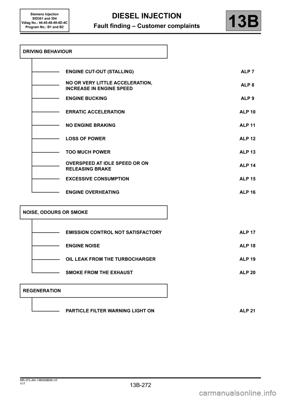
DRIVING BEHAVIOUR
ENGINE CUT-OUT (STALLING) ALP 7
NO OR VERY LITTLE ACCELERATION,
INCREASE IN ENGINE SPEEDALP 8
ENGINE BUCKING ALP 9
ERRATIC ACCELERATION ALP 10
NO ENGINE BRAKING ALP 11
LOSS OF POWER ALP 12
TOO MUCH POWER ALP 13
OVERSPEED AT IDLE SPEED OR ON
RELEASING BRAKEALP 14
EXCESSIVE CONSUMPTION ALP 15
ENGINE OVERHEATING ALP 16
NOISE, ODOURS OR SMOKE
EMISSION CONTROL NOT SATISFACTORY ALP 17
ENGINE NOISE ALP 18
OIL LEAK FROM THE TURBOCHARGER ALP 19
SMOKE FROM THE EXHAUST ALP 20
REGENERATION
PARTICLE FILTER WARNING LIGHT ON ALP 21
Page 275 of 329
13B-275
MR-372-J84-13B050$897.mif
V17
DIESEL INJECTION
Fault finding – Fault Finding Chart
Siemens Injection
SID301 and 304
Vdiag No.: 44-45-48-49-4D-4C
Program No.: B1 and B2
13B
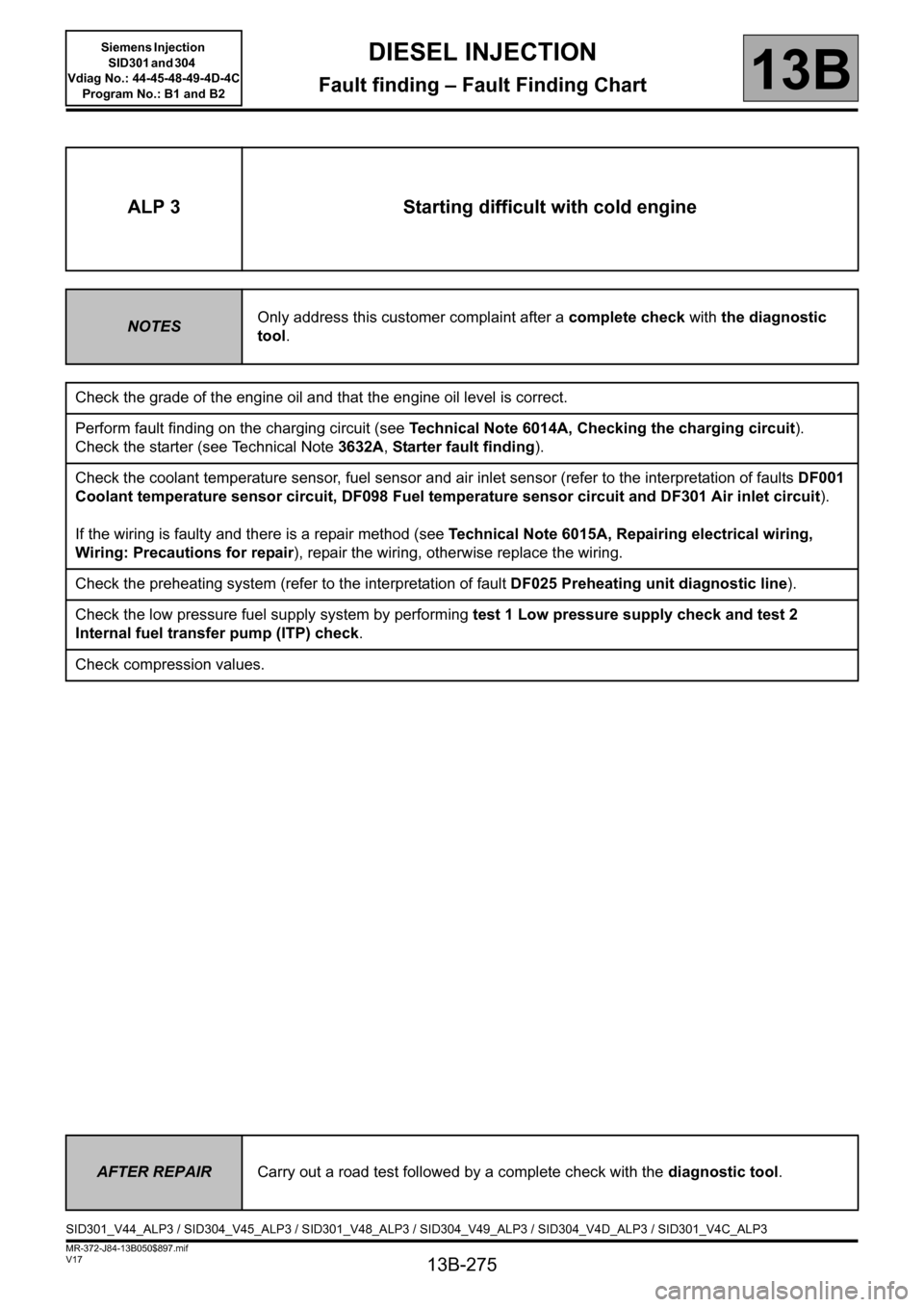
ALP 3 Starting difficult with cold engine
NOTESOnly address this customer complaint after a complete check with the diagnostic
tool.
Check the grade of the engine oil and that the engine oil level is correct.
Perform fault finding on the charging circuit (see Technical Note 6014A, Checking the charging circuit).
Check the starter (see Technical Note 3632A, Starter fault finding).
Check the coolant temperature sensor, fuel sensor and air inlet sensor (refer to the interpretation of faults DF001
Coolant temperature sensor circuit, DF098 Fuel temperature sensor circuit and DF301 Air inlet circuit).
If the wiring is faulty and there is a repair method (see Technical Note 6015A, Repairing electrical wiring,
Wiring: Precautions for repair), repair the wiring, otherwise replace the wiring.
Check the preheating system (refer to the interpretation of fault DF025 Preheating unit diagnostic line).
Check the low pressure fuel supply system by performing test 1 Low pressure supply check and test 2
Internal fuel transfer pump (ITP) check.
Check compression values.
AFTER REPAIRCarry out a road test followed by a complete check with the diagnostic tool.
SID301_V44_ALP3 / SID304_V45_ALP3 / SID301_V48_ALP3 / SID304_V49_ALP3 / SID304_V4D_ALP3 / SID301_V4C_ALP3
Page 284 of 329
13B-284
MR-372-J84-13B050$897.mif
V17
DIESEL INJECTION
Fault finding – Fault Finding Chart
Siemens Injection
SID301 and 304
Vdiag No.: 44-45-48-49-4D-4C
Program No.: B1 and B2
13B
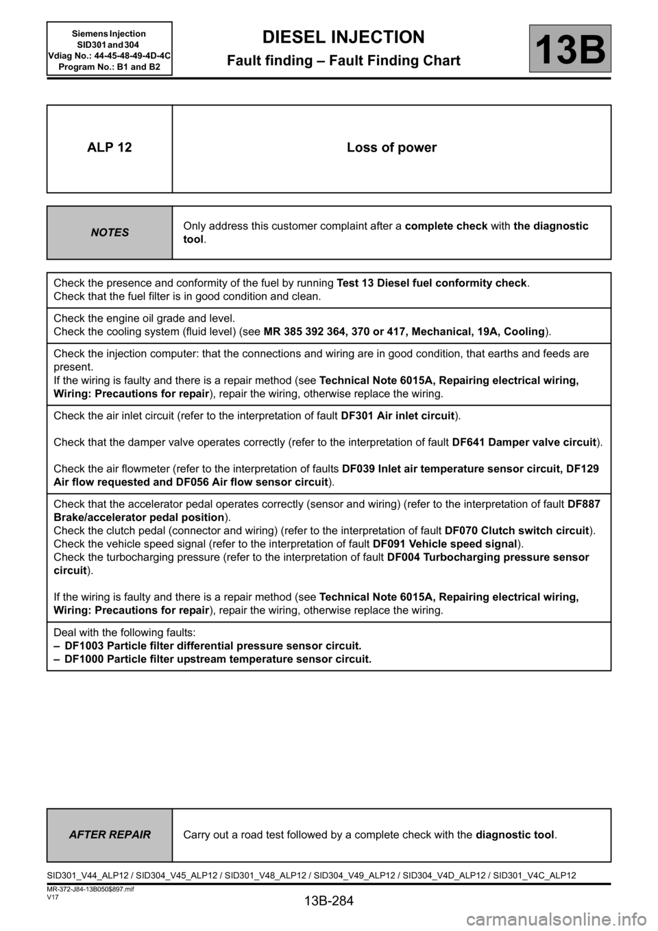
ALP 12 Loss of power
NOTESOnly address this customer complaint after a complete check with the diagnostic
tool.
Check the presence and conformity of the fuel by running Test 13 Diesel fuel conformity check.
Check that the fuel filter is in good condition and clean.
Check the engine oil grade and level.
Check the cooling system (fluid level) (see MR 385 392 364, 370 or 417, Mechanical, 19A, Cooling).
Check the injection computer: that the connections and wiring are in good condition, that earths and feeds are
present.
If the wiring is faulty and there is a repair method (see Technical Note 6015A, Repairing electrical wiring,
Wiring: Precautions for repair), repair the wiring, otherwise replace the wiring.
Check the air inlet circuit (refer to the interpretation of fault DF301 Air inlet circuit).
Check that the damper valve operates correctly (refer to the interpretation of fault DF641 Damper valve circuit).
Check the air flowmeter (refer to the interpretation of faults DF039 Inlet air temperature sensor circuit, DF129
Air flow requested and DF056 Air flow sensor circuit).
Check that the accelerator pedal operates correctly (sensor and wiring) (refer to the interpretation of fault DF887
Brake/accelerator pedal position).
Check the clutch pedal (connector and wiring) (refer to the interpretation of fault DF070 Clutch switch circuit).
Check the vehicle speed signal (refer to the interpretation of fault DF091 Vehicle speed signal).
Check the turbocharging pressure (refer to the interpretation of fault DF004 Turbocharging pressure sensor
circuit).
If the wiring is faulty and there is a repair method (see Technical Note 6015A, Repairing electrical wiring,
Wiring: Precautions for repair), repair the wiring, otherwise replace the wiring.
Deal with the following faults:
– DF1003 Particle filter differential pressure sensor circuit.
– DF1000 Particle filter upstream temperature sensor circuit.
AFTER REPAIRCarry out a road test followed by a complete check with the diagnostic tool.
SID301_V44_ALP12 / SID304_V45_ALP12 / SID301_V48_ALP12 / SID304_V49_ALP12 / SID304_V4D_ALP12 / SID301_V4C_ALP12
Page 287 of 329
13B-287
MR-372-J84-13B050$897.mif
V17
DIESEL INJECTION
Fault finding – Fault Finding Chart
Siemens Injection
SID301 and 304
Vdiag No.: 44-45-48-49-4D-4C
Program No.: B1 and B2
13B
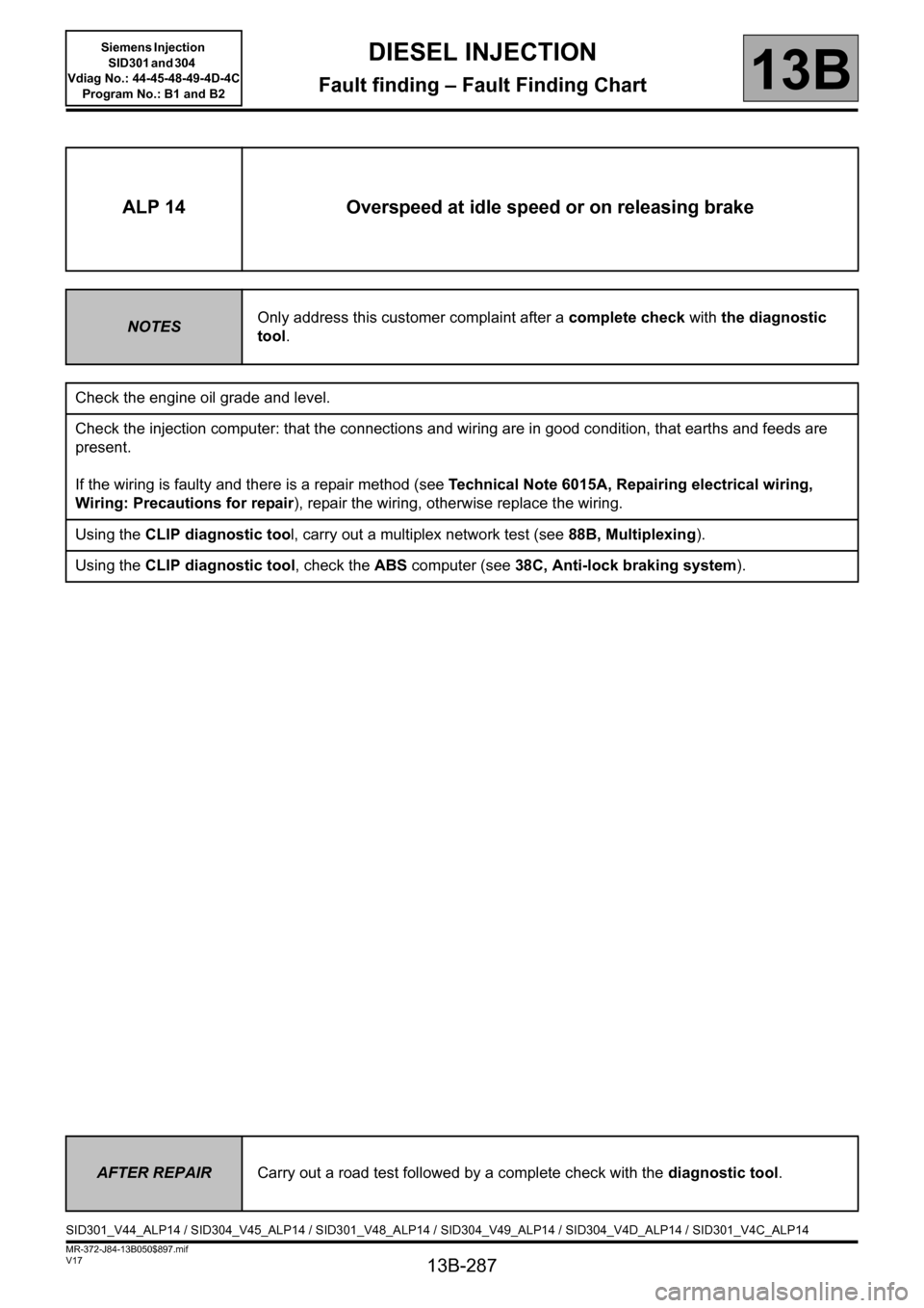
ALP 14 Overspeed at idle speed or on releasing brake
NOTESOnly address this customer complaint after a complete check with the diagnostic
tool.
Check the engine oil grade and level.
Check the injection computer: that the connections and wiring are in good condition, that earths and feeds are
present.
If the wiring is faulty and there is a repair method (see Technical Note 6015A, Repairing electrical wiring,
Wiring: Precautions for repair), repair the wiring, otherwise replace the wiring.
Using the CLIP diagnostic tool, carry out a multiplex network test (see 88B, Multiplexing).
Using the CLIP diagnostic tool, check the ABS computer (see 38C, Anti-lock braking system).
AFTER REPAIRCarry out a road test followed by a complete check with the diagnostic tool.
SID301_V44_ALP14 / SID304_V45_ALP14 / SID301_V48_ALP14 / SID304_V49_ALP14 / SID304_V4D_ALP14 / SID301_V4C_ALP14
Page 291 of 329
13B-291
MR-372-J84-13B050$897.mif
V17
Siemens Injection
SID301 and 304
Vdiag No.: 44-45-48-49-4D-4C
Program No.: B1 and B2DIESEL INJECTION
Fault finding – Fault Finding Chart13B
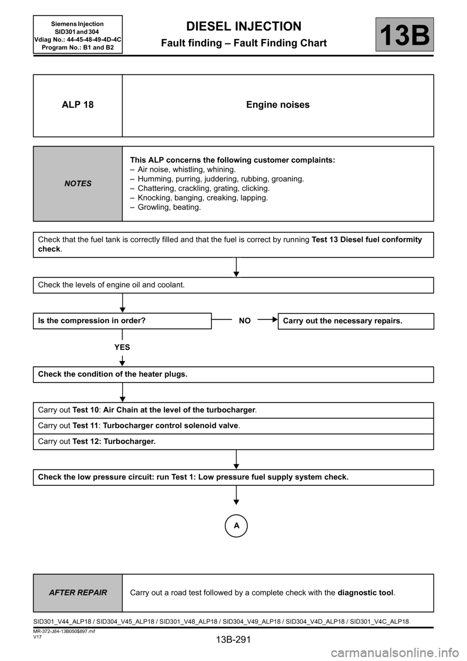
ALP 18 Engine noises
NOTESThis ALP concerns the following customer complaints:
– Air noise, whistling, whining.
– Humming, purring, juddering, rubbing, groaning.
– Chattering, crackling, grating, clicking.
– Knocking, banging, creaking, lapping.
– Growling, beating.
Check that the fuel tank is correctly filled and that the fuel is correct by running Test 13 Diesel fuel conformity
check.
Check the levels of engine oil and coolant.
Is the compression in order?
YES
Check the condition of the heater plugs.
Carry out Te s t 1 0: Air Chain at the level of the turbocharger.
Carry out Te s t 11: Turbocharger control solenoid valve.
Carry out Test 12: Turbocharger.
Check the low pressure circuit: run Test 1: Low pressure fuel supply system check.
NO Carry out the necessary repairs.
AFTER REPAIRCarry out a road test followed by a complete check with the diagnostic tool.
SID301_V44_ALP18 / SID304_V45_ALP18 / SID301_V48_ALP18 / SID304_V49_ALP18 / SID304_V4D_ALP18 / SID301_V4C_ALP18
A
Page 293 of 329
13B-293
MR-372-J84-13B050$897.mif
V17
Siemens Injection
SID301 and 304
Vdiag No.: 44-45-48-49-4D-4C
Program No.: B1 and B2DIESEL INJECTION
Fault finding – Fault Finding Chart13B
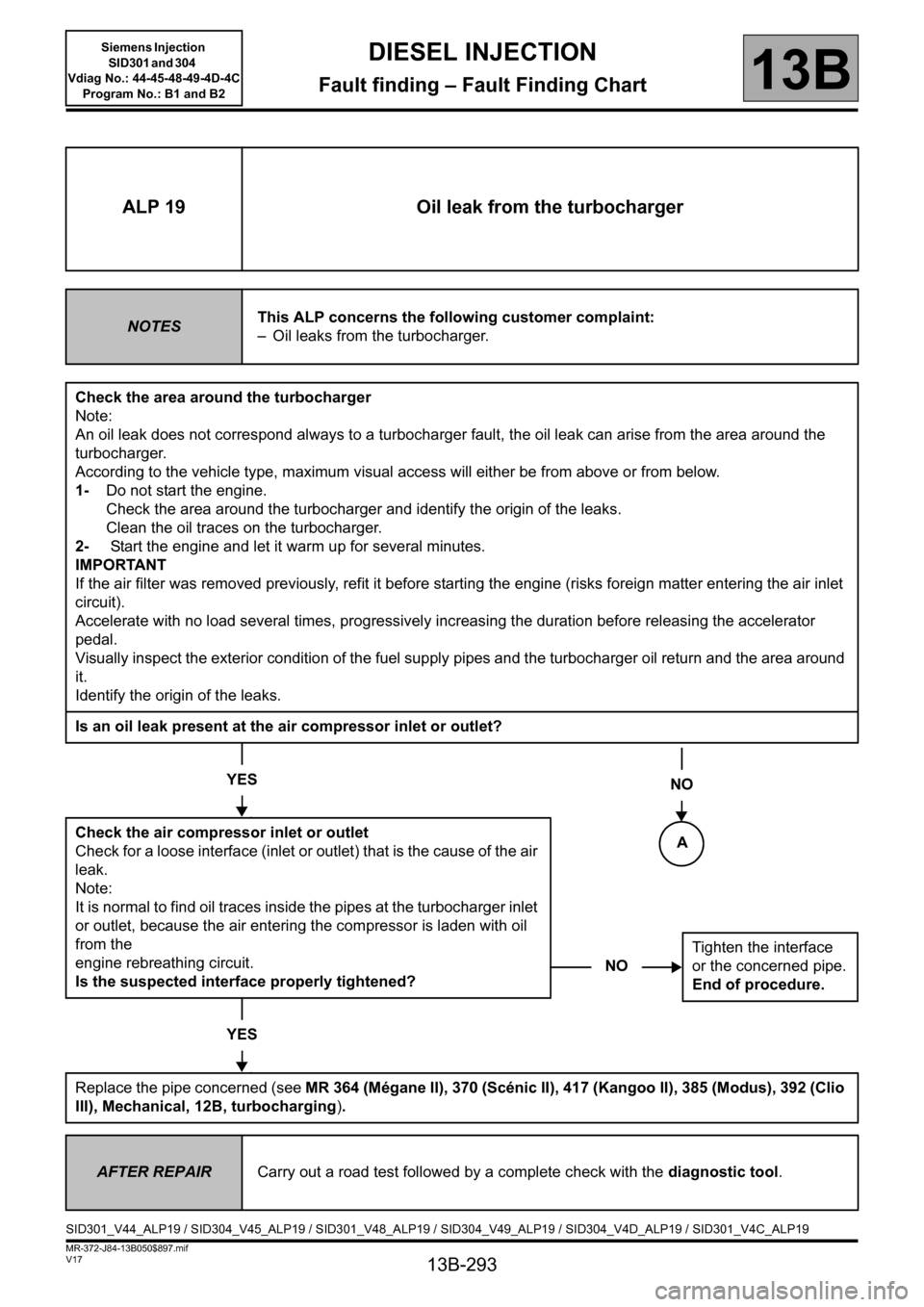
NOTighten the interface
or the concerned pipe.
End of procedure.
ALP 19 Oil leak from the turbocharger
NOTESThis ALP concerns the following customer complaint:
– Oil leaks from the turbocharger.
Check the area around the turbocharger
Note:
An oil leak does not correspond always to a turbocharger fault, the oil leak can arise from the area around the
turbocharger.
According to the vehicle type, maximum visual access will either be from above or from below.
1-Do not start the engine.
Check the area around the turbocharger and identify the origin of the leaks.
Clean the oil traces on the turbocharger.
2- Start the engine and let it warm up for several minutes.
IMPORTANT
If the air filter was removed previously, refit it before starting the engine (risks foreign matter entering the air inlet
circuit).
Accelerate with no load several times, progressively increasing the duration before releasing the accelerator
pedal.
Visually inspect the exterior condition of the fuel supply pipes and the turbocharger oil return and the area around
it.
Identify the origin of the leaks.
Is an oil leak present at the air compressor inlet or outlet?
YES
Check the air compressor inlet or outlet
Check for a loose interface (inlet or outlet) that is the cause of the air
leak.
Note:
It is normal to find oil traces inside the pipes at the turbocharger inlet
or outlet, because the air entering the compressor is laden with oil
from the
engine rebreathing circuit.
Is the suspected interface properly tightened?
YES
Replace the pipe concerned (see MR 364 (Mégane II), 370 (Scénic II), 417 (Kangoo II), 385 (Modus), 392 (Clio
III), Mechanical, 12B, turbocharging).
NO
AFTER REPAIRCarry out a road test followed by a complete check with the diagnostic tool.
SID301_V44_ALP19 / SID304_V45_ALP19 / SID301_V48_ALP19 / SID304_V49_ALP19 / SID304_V4D_ALP19 / SID301_V4C_ALP19
A
Page 294 of 329

13B-294
MR-372-J84-13B050$897.mif
V17
DIESEL INJECTION
Fault finding – Fault Finding Chart
Siemens Injection
SID301 and 304
Vdiag No.: 44-45-48-49-4D-4C
Program No.: B1 and B2
13B
ALP 19
CONTINUED 1
Is an oil leak present only at the casing of the compressor section?
YES NO
The turbocharger is not faulty. The oil leak is
from another engine component and the oil is
flowing onto the turbocharger.
AFTER REPAIRCarry out a road test followed by a complete check with the diagnostic tool.
A
B
Page 295 of 329

13B-295
MR-372-J84-13B050$897.mif
V17
Siemens Injection
SID301 and 304
Vdiag No.: 44-45-48-49-4D-4C
Program No.: B1 and B2DIESEL INJECTION
Fault finding – Fault Finding Chart13B
NO
End of procedure.
ALP 19
CONTINUED 2
Is an oil leak present at the turbocharger oil supply inlet or outlet?
YESNO
Check the turbocharger oil supply inlet and
outlet
Check for a loose interface (inlet or outlet) that is
the cause of the oil leak.
Is the suspected interface properly
tightened?
YES
Only replace the seal or pipe of the part concerned (see MR 364 (Mégane II), 370 (Scénic II), 417
(Kangoo II), 385 (Modus), 392 (Clio III), Mechanical, 12B, turbocharging).
Is an oil leak present at the interfaces of the turbine casing and the exhaust pipes?
YES
The turbocharger is not faulty. There is probably another fault in the engine.
Mark the component from which arises the leak and refer to the repair manual (see MR 364 (Mégane II), 370
(Scénic II), 417 (Kangoo II), 385 (Modus), 392 (Clio III), 10A Engine and Peripherals).
NOTighten the pipe concerned.
End of procedure.
AFTER REPAIRCarry out a road test followed by a complete check with the diagnostic tool.
B
Page 296 of 329
13B-296
MR-372-J84-13B050$897.mif
V17
Siemens Injection
SID301 and 304
Vdiag No.: 44-45-48-49-4D-4C
Program No.: B1 and B2DIESEL INJECTION
Fault finding – Fault Finding Chart13B
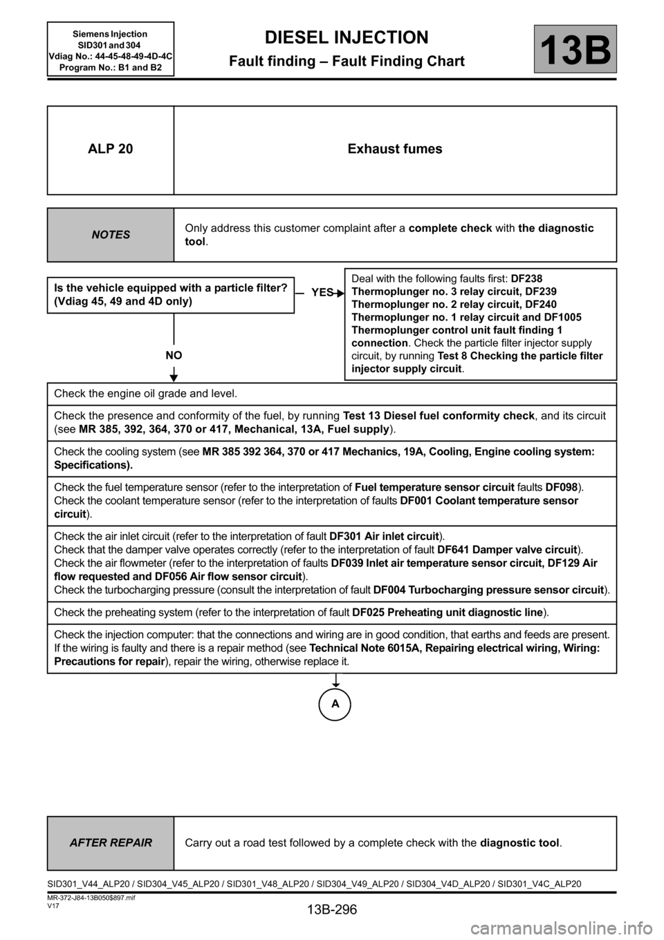
ALP 20 Exhaust fumes
NOTESOnly address this customer complaint after a complete check with the diagnostic
tool.
Is the vehicle equipped with a particle filter?
(Vdiag 45, 49 and 4D only)
NO
Check the engine oil grade and level.
Check the presence and conformity of the fuel, by running Test 13 Diesel fuel conformity check, and its circuit
(see MR 385, 392, 364, 370 or 417, Mechanical, 13A, Fuel supply).
Check the cooling system (see MR 385 392 364, 370 or 417 Mechanics, 19A, Cooling, Engine cooling system:
Specifications).
Check the fuel temperature sensor (refer to the interpretation of Fuel temperature sensor circuit faults DF098).
Check the coolant temperature sensor (refer to the interpretation of faults DF001 Coolant temperature sensor
circuit).
Check the air inlet circuit (refer to the interpretation of fault DF301 Air inlet circuit).
Check that the damper valve operates correctly (refer to the interpretation of fault DF641 Damper valve circuit).
Check the air flowmeter (refer to the interpretation of faults DF039 Inlet air temperature sensor circuit, DF129 Air
flow requested and DF056 Air flow sensor circuit).
Check the turbocharging pressure (consult the interpretation of fault DF004 Turbocharging pressure sensor circuit).
Check the preheating system (refer to the interpretation of fault DF025 Preheating unit diagnostic line).
Check the injection computer: that the connections and wiring are in good condition, that earths and feeds are present.
If the wiring is faulty and there is a repair method (see Technical Note 6015A, Repairing electrical wiring, Wiring:
Precautions for repair), repair the wiring, otherwise replace it.
YES
Deal with the following faults first: DF238
Thermoplunger no. 3 relay circuit, DF239
Thermoplunger no. 2 relay circuit, DF240
Thermoplunger no. 1 relay circuit and DF1005
Thermoplunger control unit fault finding 1
connection. Check the particle filter injector supply
circuit, by running Test 8 Checking the particle filter
injector supply circuit.
AFTER REPAIRCarry out a road test followed by a complete check with the diagnostic tool.
SID301_V44_ALP20 / SID304_V45_ALP20 / SID301_V48_ALP20 / SID304_V49_ALP20 / SID304_V4D_ALP20 / SID301_V4C_ALP20
A
Page 307 of 329
13B-307
MR-372-J84-13B050$936.mif
V17
Siemens Injection
SID301 and 304
Vdiag No.: 44-45-48-49-4D-4C
Program No.: B1 and B2DIESEL INJECTION
Fault finding – Tests13B
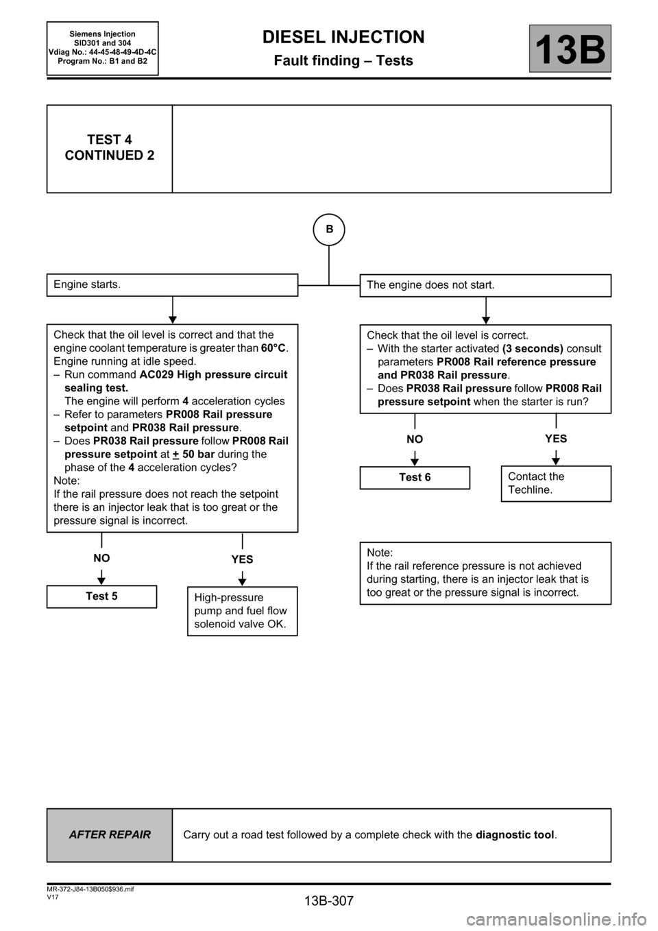
TEST 4
CONTINUED 2
Engine starts.
Check that the oil level is correct and that the
engine coolant temperature is greater than 60°C.
Engine running at idle speed.
– Run command AC029 High pressure circuit
sealing test.
The engine will perform 4acceleration cycles
– Refer to parameters PR008 Rail pressure
setpoint and PR038 Rail pressure.
–Does PR038 Rail pressure follow PR008 Rail
pressure setpoint at +
50 bar during the
phase of the 4 acceleration cycles?
Note:
If the rail pressure does not reach the setpoint
there is an injector leak that is too great or the
pressure signal is incorrect.
NO
Test 5
YES
High-pressure
pump and fuel flow
solenoid valve OK.
The engine does not start.
Check that the oil level is correct.
– With the starter activated (3 seconds) consult
parameters PR008 Rail reference pressure
and PR038 Rail pressure.
–Does PR038 Rail pressure follow PR008 Rail
pressure setpoint when the starter is run?
NO
Test 6
YES
Contact the
Techline.
Note:
If the rail reference pressure is not achieved
during starting, there is an injector leak that is
too great or the pressure signal is incorrect.
AFTER REPAIRCarry out a road test followed by a complete check with the diagnostic tool.
B