oil filter RENAULT SCENIC 2011 J95 / 3.G Engine And Peripherals Siemens Injection User Guide
[x] Cancel search | Manufacturer: RENAULT, Model Year: 2011, Model line: SCENIC, Model: RENAULT SCENIC 2011 J95 / 3.GPages: 329, PDF Size: 1.71 MB
Page 284 of 329
13B-284
MR-372-J84-13B050$897.mif
V17
DIESEL INJECTION
Fault finding – Fault Finding Chart
Siemens Injection
SID301 and 304
Vdiag No.: 44-45-48-49-4D-4C
Program No.: B1 and B2
13B
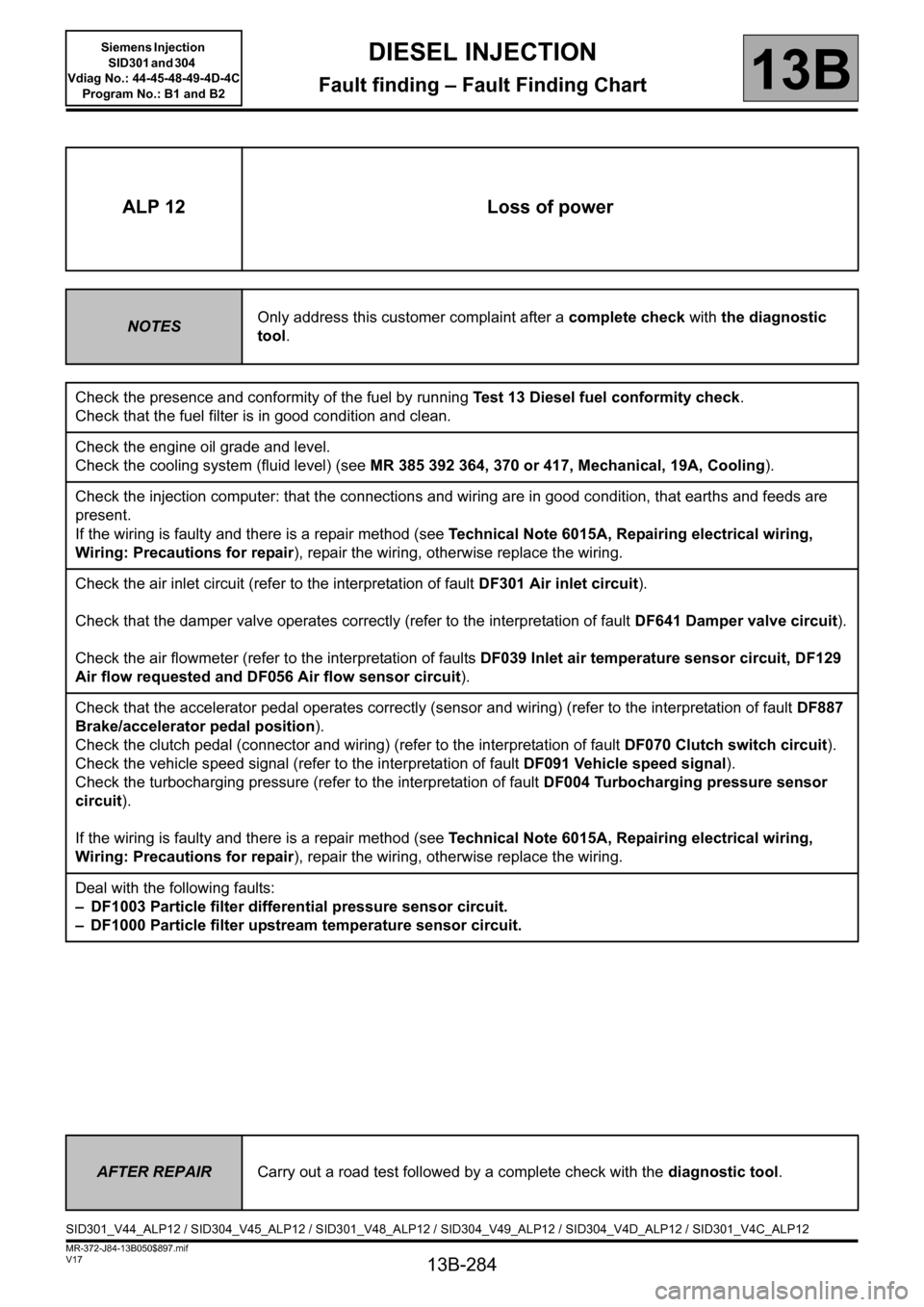
ALP 12 Loss of power
NOTESOnly address this customer complaint after a complete check with the diagnostic
tool.
Check the presence and conformity of the fuel by running Test 13 Diesel fuel conformity check.
Check that the fuel filter is in good condition and clean.
Check the engine oil grade and level.
Check the cooling system (fluid level) (see MR 385 392 364, 370 or 417, Mechanical, 19A, Cooling).
Check the injection computer: that the connections and wiring are in good condition, that earths and feeds are
present.
If the wiring is faulty and there is a repair method (see Technical Note 6015A, Repairing electrical wiring,
Wiring: Precautions for repair), repair the wiring, otherwise replace the wiring.
Check the air inlet circuit (refer to the interpretation of fault DF301 Air inlet circuit).
Check that the damper valve operates correctly (refer to the interpretation of fault DF641 Damper valve circuit).
Check the air flowmeter (refer to the interpretation of faults DF039 Inlet air temperature sensor circuit, DF129
Air flow requested and DF056 Air flow sensor circuit).
Check that the accelerator pedal operates correctly (sensor and wiring) (refer to the interpretation of fault DF887
Brake/accelerator pedal position).
Check the clutch pedal (connector and wiring) (refer to the interpretation of fault DF070 Clutch switch circuit).
Check the vehicle speed signal (refer to the interpretation of fault DF091 Vehicle speed signal).
Check the turbocharging pressure (refer to the interpretation of fault DF004 Turbocharging pressure sensor
circuit).
If the wiring is faulty and there is a repair method (see Technical Note 6015A, Repairing electrical wiring,
Wiring: Precautions for repair), repair the wiring, otherwise replace the wiring.
Deal with the following faults:
– DF1003 Particle filter differential pressure sensor circuit.
– DF1000 Particle filter upstream temperature sensor circuit.
AFTER REPAIRCarry out a road test followed by a complete check with the diagnostic tool.
SID301_V44_ALP12 / SID304_V45_ALP12 / SID301_V48_ALP12 / SID304_V49_ALP12 / SID304_V4D_ALP12 / SID301_V4C_ALP12
Page 293 of 329
13B-293
MR-372-J84-13B050$897.mif
V17
Siemens Injection
SID301 and 304
Vdiag No.: 44-45-48-49-4D-4C
Program No.: B1 and B2DIESEL INJECTION
Fault finding – Fault Finding Chart13B
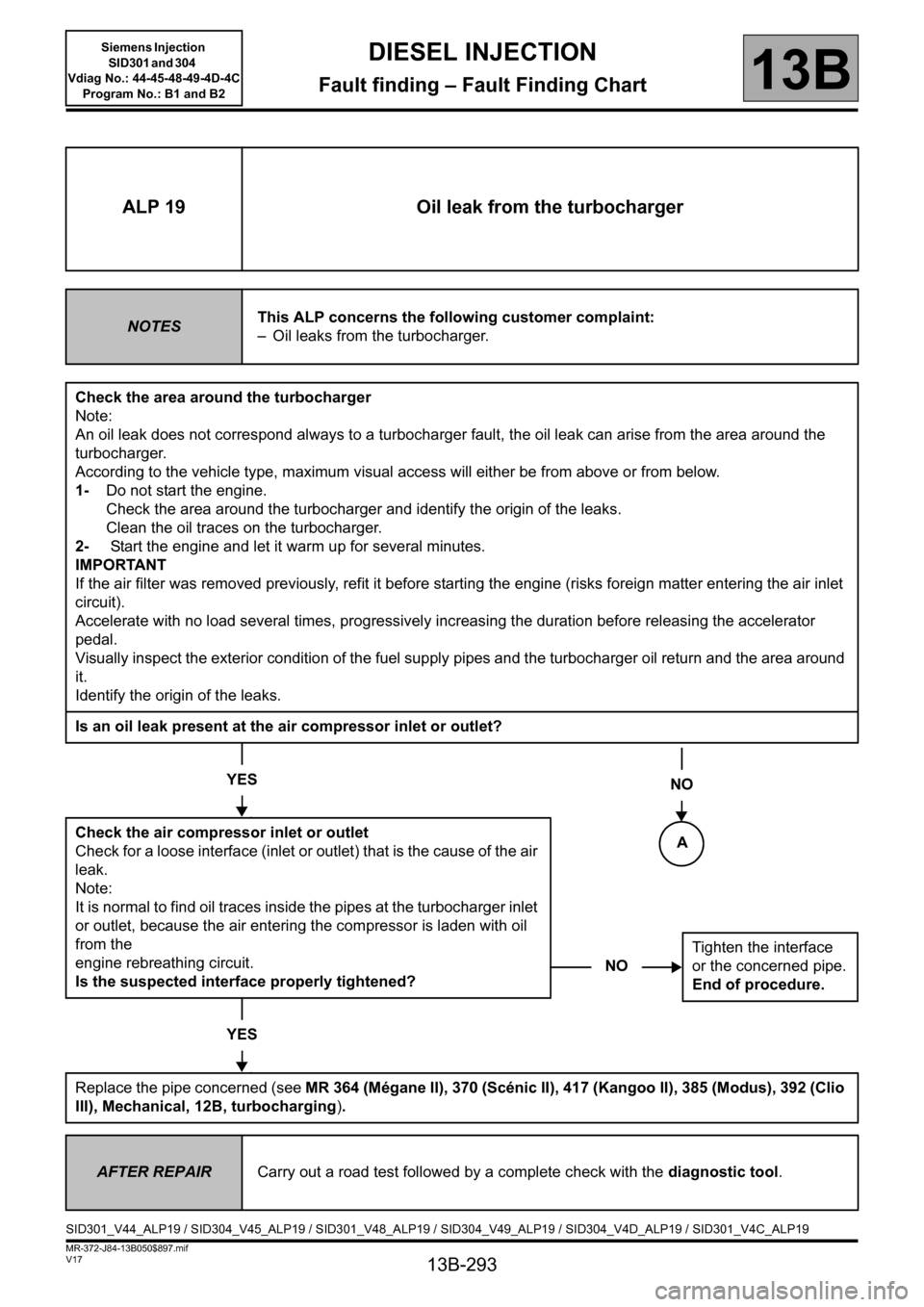
NOTighten the interface
or the concerned pipe.
End of procedure.
ALP 19 Oil leak from the turbocharger
NOTESThis ALP concerns the following customer complaint:
– Oil leaks from the turbocharger.
Check the area around the turbocharger
Note:
An oil leak does not correspond always to a turbocharger fault, the oil leak can arise from the area around the
turbocharger.
According to the vehicle type, maximum visual access will either be from above or from below.
1-Do not start the engine.
Check the area around the turbocharger and identify the origin of the leaks.
Clean the oil traces on the turbocharger.
2- Start the engine and let it warm up for several minutes.
IMPORTANT
If the air filter was removed previously, refit it before starting the engine (risks foreign matter entering the air inlet
circuit).
Accelerate with no load several times, progressively increasing the duration before releasing the accelerator
pedal.
Visually inspect the exterior condition of the fuel supply pipes and the turbocharger oil return and the area around
it.
Identify the origin of the leaks.
Is an oil leak present at the air compressor inlet or outlet?
YES
Check the air compressor inlet or outlet
Check for a loose interface (inlet or outlet) that is the cause of the air
leak.
Note:
It is normal to find oil traces inside the pipes at the turbocharger inlet
or outlet, because the air entering the compressor is laden with oil
from the
engine rebreathing circuit.
Is the suspected interface properly tightened?
YES
Replace the pipe concerned (see MR 364 (Mégane II), 370 (Scénic II), 417 (Kangoo II), 385 (Modus), 392 (Clio
III), Mechanical, 12B, turbocharging).
NO
AFTER REPAIRCarry out a road test followed by a complete check with the diagnostic tool.
SID301_V44_ALP19 / SID304_V45_ALP19 / SID301_V48_ALP19 / SID304_V49_ALP19 / SID304_V4D_ALP19 / SID301_V4C_ALP19
A
Page 296 of 329
13B-296
MR-372-J84-13B050$897.mif
V17
Siemens Injection
SID301 and 304
Vdiag No.: 44-45-48-49-4D-4C
Program No.: B1 and B2DIESEL INJECTION
Fault finding – Fault Finding Chart13B
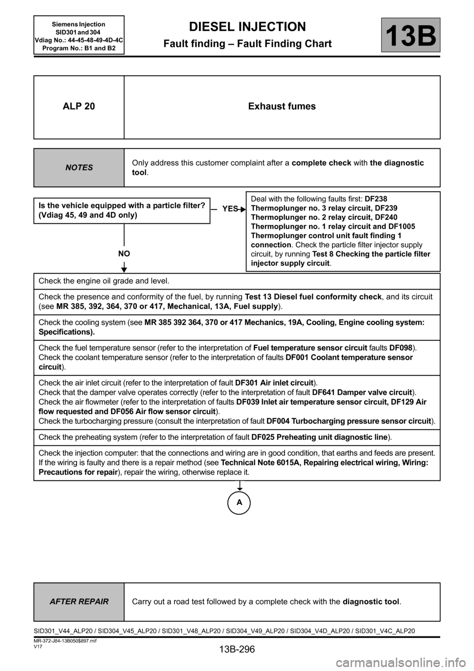
ALP 20 Exhaust fumes
NOTESOnly address this customer complaint after a complete check with the diagnostic
tool.
Is the vehicle equipped with a particle filter?
(Vdiag 45, 49 and 4D only)
NO
Check the engine oil grade and level.
Check the presence and conformity of the fuel, by running Test 13 Diesel fuel conformity check, and its circuit
(see MR 385, 392, 364, 370 or 417, Mechanical, 13A, Fuel supply).
Check the cooling system (see MR 385 392 364, 370 or 417 Mechanics, 19A, Cooling, Engine cooling system:
Specifications).
Check the fuel temperature sensor (refer to the interpretation of Fuel temperature sensor circuit faults DF098).
Check the coolant temperature sensor (refer to the interpretation of faults DF001 Coolant temperature sensor
circuit).
Check the air inlet circuit (refer to the interpretation of fault DF301 Air inlet circuit).
Check that the damper valve operates correctly (refer to the interpretation of fault DF641 Damper valve circuit).
Check the air flowmeter (refer to the interpretation of faults DF039 Inlet air temperature sensor circuit, DF129 Air
flow requested and DF056 Air flow sensor circuit).
Check the turbocharging pressure (consult the interpretation of fault DF004 Turbocharging pressure sensor circuit).
Check the preheating system (refer to the interpretation of fault DF025 Preheating unit diagnostic line).
Check the injection computer: that the connections and wiring are in good condition, that earths and feeds are present.
If the wiring is faulty and there is a repair method (see Technical Note 6015A, Repairing electrical wiring, Wiring:
Precautions for repair), repair the wiring, otherwise replace it.
YES
Deal with the following faults first: DF238
Thermoplunger no. 3 relay circuit, DF239
Thermoplunger no. 2 relay circuit, DF240
Thermoplunger no. 1 relay circuit and DF1005
Thermoplunger control unit fault finding 1
connection. Check the particle filter injector supply
circuit, by running Test 8 Checking the particle filter
injector supply circuit.
AFTER REPAIRCarry out a road test followed by a complete check with the diagnostic tool.
SID301_V44_ALP20 / SID304_V45_ALP20 / SID301_V48_ALP20 / SID304_V49_ALP20 / SID304_V4D_ALP20 / SID301_V4C_ALP20
A
Page 323 of 329
13B-323
MR-372-J84-13B050$936.mif
V17
DIESEL INJECTION
Fault finding – Tests
Siemens Injection
SID301 and 304
Vdiag No.: 44-45-48-49-4D-4C
Program No.: B1 and B2
13B
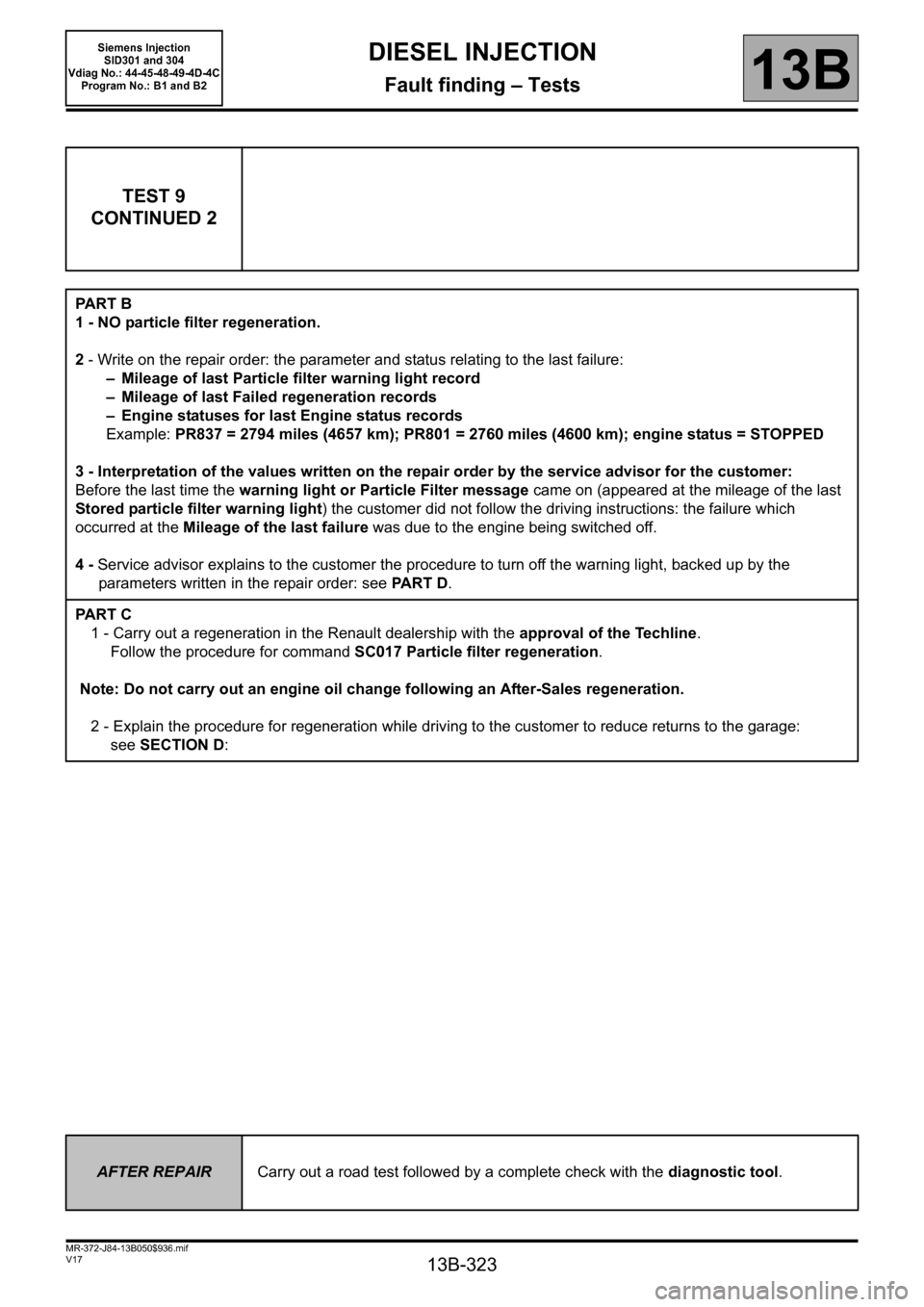
TEST 9
CONTINUED 2
PA R T B
1 - NO particle filter regeneration.
2 - Write on the repair order: the parameter and status relating to the last failure:
– Mileage of last Particle filter warning light record
– Mileage of last Failed regeneration records
– Engine statuses for last Engine status records
Example: PR837 = 2794 miles (4657 km); PR801 = 2760 miles (4600 km); engine status = STOPPED
3 - Interpretation of the values written on the repair order by the service advisor for the customer:
Before the last time the warning light or Particle Filter message came on (appeared at the mileage of the last
Stored particle filter warning light) the customer did not follow the driving instructions: the failure which
occurred at the Mileage of the last failure was due to the engine being switched off.
4 - Service advisor explains to the customer the procedure to turn off the warning light, backed up by the
parameters written in the repair order: see PA R T D.
PA R T C
1 - Carry out a regeneration in the Renault dealership with the approval of the Techline.
Follow the procedure for command SC017 Particle filter regeneration.
Note: Do not carry out an engine oil change following an After-Sales regeneration.
2 - Explain the procedure for regeneration while driving to the customer to reduce returns to the garage:
see SECTION D:
AFTER REPAIRCarry out a road test followed by a complete check with the diagnostic tool.
Page 324 of 329
13B-324
MR-372-J84-13B050$936.mif
V17
DIESEL INJECTION
Fault finding – Tests
Siemens Injection
SID301 and 304
Vdiag No.: 44-45-48-49-4D-4C
Program No.: B1 and B2
13B
TEST 9
CONTINUED 3
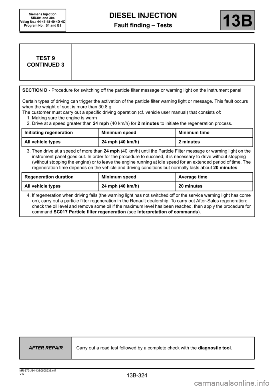
SECTION D - Procedure for switching off the particle filter message or warning light on the instrument panel
Certain types of driving can trigger the activation of the particle filter warning light or message. This fault occurs
when the weight of soot is more than 30.8 g.
The customer must carry out a specific driving operation (cf. vehicle user manual) that consists of:
1. Making sure the engine is warm
2. Drive at a speed greater than 24 mph (40 km/h) for 2 minutes to initiate the regeneration process.
Initiating regeneration Minimum speed Minimum time
All vehicle types 24 mph (40 km/h) 2 minutes
3. Then drive at a speed of more than 24 mph (40 km/h) until the Particle Filter message or warning light on the
instrument panel goes out. In order for the procedure to succeed, it is necessary to drive without stopping
(without stopping the engine) or to leave the engine running at idle speed for an extended period of time. The
regeneration time depends on the vehicle and driving conditions but normally lasts about 20 minutes.
Regeneration duration Minimum speed Average time
All vehicle types 24 mph (40 km/h) 20 minutes
4. If regeneration when driving fails (the warning light has not switched off or the service warning light has come
on), carry out a particle filter regeneration in the Renault dealership. To carry out After-Sales regeneration:
check the oil level and remove some oil if the maximum level has been reached, then apply the procedure for
command SC017 Particle filter regeneration (see Interpretation of commands).
AFTER REPAIRCarry out a road test followed by a complete check with the diagnostic tool.