DF773 RENAULT SCENIC 2011 J95 / 3.G Engine And Peripherals Siemens Injection Workshop Manual
[x] Cancel search | Manufacturer: RENAULT, Model Year: 2011, Model line: SCENIC, Model: RENAULT SCENIC 2011 J95 / 3.GPages: 329, PDF Size: 1.71 MB
Page 33 of 329

13B-33
MR-372-J84-13B050$351.mif
V17
Siemens Injection
SID301 and 304
Vdiag No.: 44-45-48-49-4D-4C
Program No.: B1 and B2DIESEL INJECTION
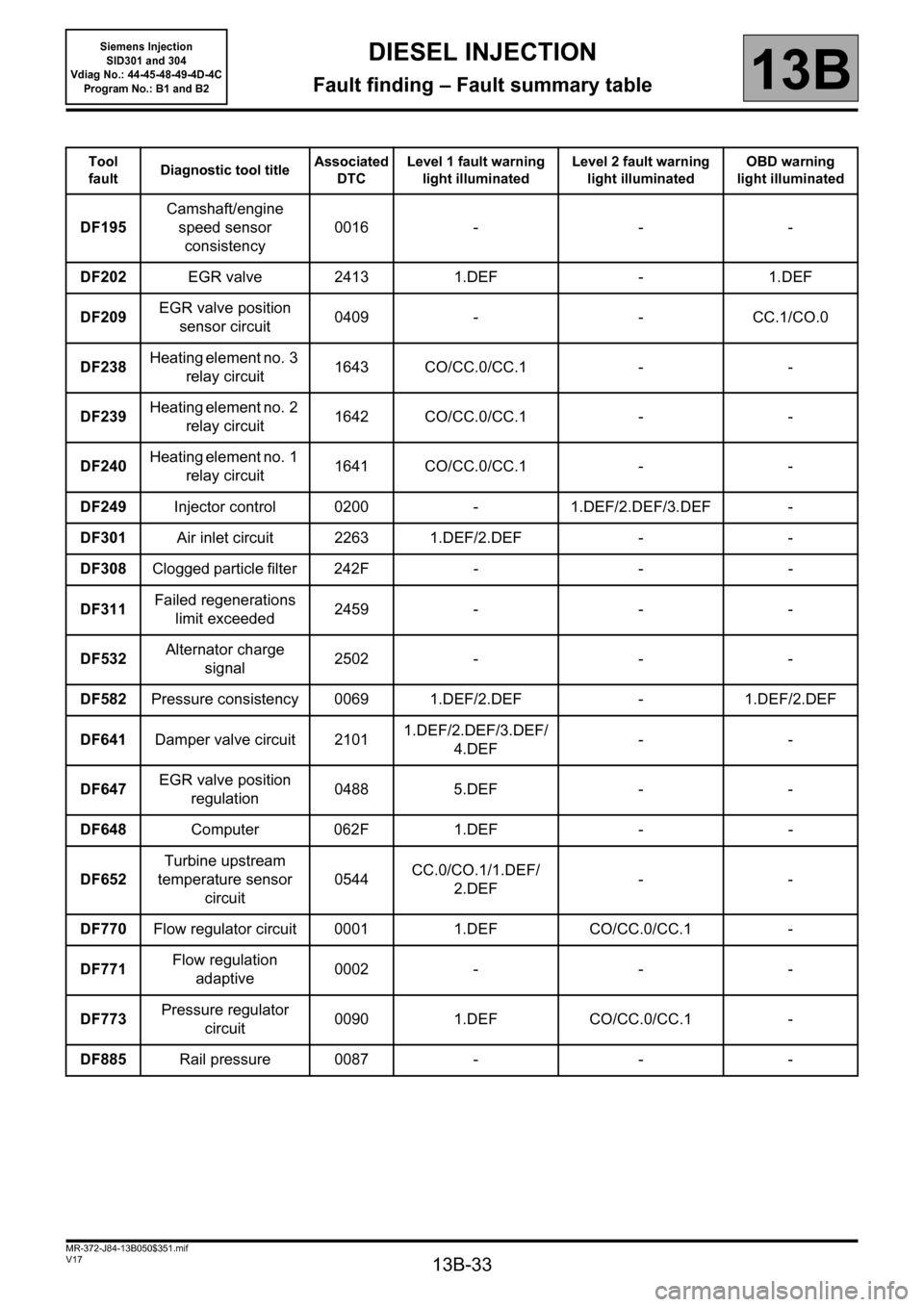
Fault finding – Fault summary table13B
Tool
faultDiagnostic tool titleAssociated
DTCLevel 1 fault warning
light illuminatedLevel 2 fault warning
light illuminatedOBD warning
light illuminated
DF195Camshaft/engine
speed sensor
consistency0016 - - -
DF202EGR valve 2413 1.DEF - 1.DEF
DF209EGR valve position
sensor circuit0409 - - CC.1/CO.0
DF238Heating element no. 3
relay circuit 1643 CO/CC.0/CC.1 - -
DF239Heating element no. 2
relay circuit 1642 CO/CC.0/CC.1 - -
DF240Heating element no. 1
relay circuit 1641 CO/CC.0/CC.1 - -
DF249Injector control 0200 - 1.DEF/2.DEF/3.DEF -
DF301Air inlet circuit 2263 1.DEF/2.DEF - -
DF308Clogged particle filter 242F - - -
DF311Failed regenerations
limit exceeded 2459 - - -
DF532Alternator charge
signal2502 - - -
DF582Pressure consistency 0069 1.DEF/2.DEF - 1.DEF/2.DEF
DF641Damper valve circuit 21011.DEF/2.DEF/3.DEF/
4.DEF--
DF647EGR valve position
regulation0488 5.DEF - -
DF648Computer 062F 1.DEF - -
DF652Turbine upstream
temperature sensor
circuit 0544CC.0/CO.1/1.DEF/
2.DEF--
DF770Flow regulator circuit 0001 1.DEF CO/CC.0/CC.1 -
DF771Flow regulation
adaptive0002 - - -
DF773Pressure regulator
circuit0090 1.DEF CO/CC.0/CC.1 -
DF885Rail pressure 0087 - - -
Page 98 of 329

13B-98
MR-372-J84-13B050$468.mif
V17
DIESEL INJECTION
Fault finding – Interpretation of faults
Siemens Injection
SID301 and 304
Vdiag No.: 44-45-48-49-4D-4C
Program No.: B1 and B2
13B
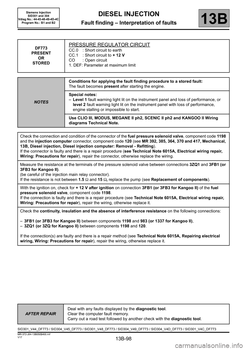
DF773
PRESENT
OR
STOREDPRESSURE REGULATOR CIRCUIT
CC.0 : Short circuit to earth
CC.1 : Short circuit to + 12 V
CO : Open circuit
1. DEF: Parameter at maximum limit
NOTESConditions for applying the fault finding procedure to a stored fault:
The fault becomes present after starting the engine.
Special notes:
–Level 1 fault warning light lit on the instrument panel and loss of performance, or
level 2 fault warning light lit on the instrument panel with loss of performance,
engine stalling or impossible to start.
Use CLIO III, MODUS, MEGANE II ph2, SCENIC II ph2 and KANGOO II Wiring
diagrams Technical Note.
Check the connection and condition of the connector of the fuel pressure solenoid valve, component code 119 8
and the injection computer connector, component code 120 (see MR 392, 385, 364, 370 and 417, Mechanical,
13B, Diesel injection, Diesel injection computer: Removal - Refitting).
If the connector is faulty and there is a repair procedure (see Technical Note 6015A, Electrical wiring repair,
Wiring: Precautions for repair), repair the connector, otherwise replace the wiring.
Measure the resistance at the terminals of the pressure solenoid valve between connections 3ZQ1 and 3FB1 (or
3FB3 for Kangoo II).
(be careful of the injection main relay connector).
If the resistance is not between 1.5 Ω and 15 Ω, replace the pump (see Replacement of components).
With the ignition on, check for + 12 V after ignition on connection 3FB1 (or 3FB3 for Kangoo II) of the fuel
pressure solenoid valve, component code 1198.
If the connection is faulty and there is a repair procedure (see Technical Note 6015A, Electrical wiring repair,
Wiring: Precautions for repair), repair the wiring, otherwise replace it.
Check the continuity, insulation and the absence of interference resistance on the following connections:
–3FB1 (or 3FB3 for Kangoo II) between components 1198 and 983 (or 1337 for Kangoo II),
–3ZQ1 (or 3ZQ for Kangoo II) between components 1198 and 120.
If the connection(s) are faulty and there is a repair method (see Technical Note 6015A, Repairing electrical
wiring, Wiring: Precautions for repair), repair the wiring, otherwise replace it.
AFTER REPAIRDeal with any faults displayed by the diagnostic tool.
Clear the computer fault memory.
Carry out a road test followed by another check with the diagnostic tool.
SID301_V44_DF773 / SID304_V45_DF773 / SID301_V48_DF773 / SID304_V49_DF773 / SID304_V4D_DF773 / SID301_V4C_DF773
Page 99 of 329

13B-99
MR-372-J84-13B050$468.mif
V17
DIESEL INJECTION
Fault finding – Interpretation of faults
Siemens Injection
SID301 and 304
Vdiag No.: 44-45-48-49-4D-4C
Program No.: B1 and B2
13B
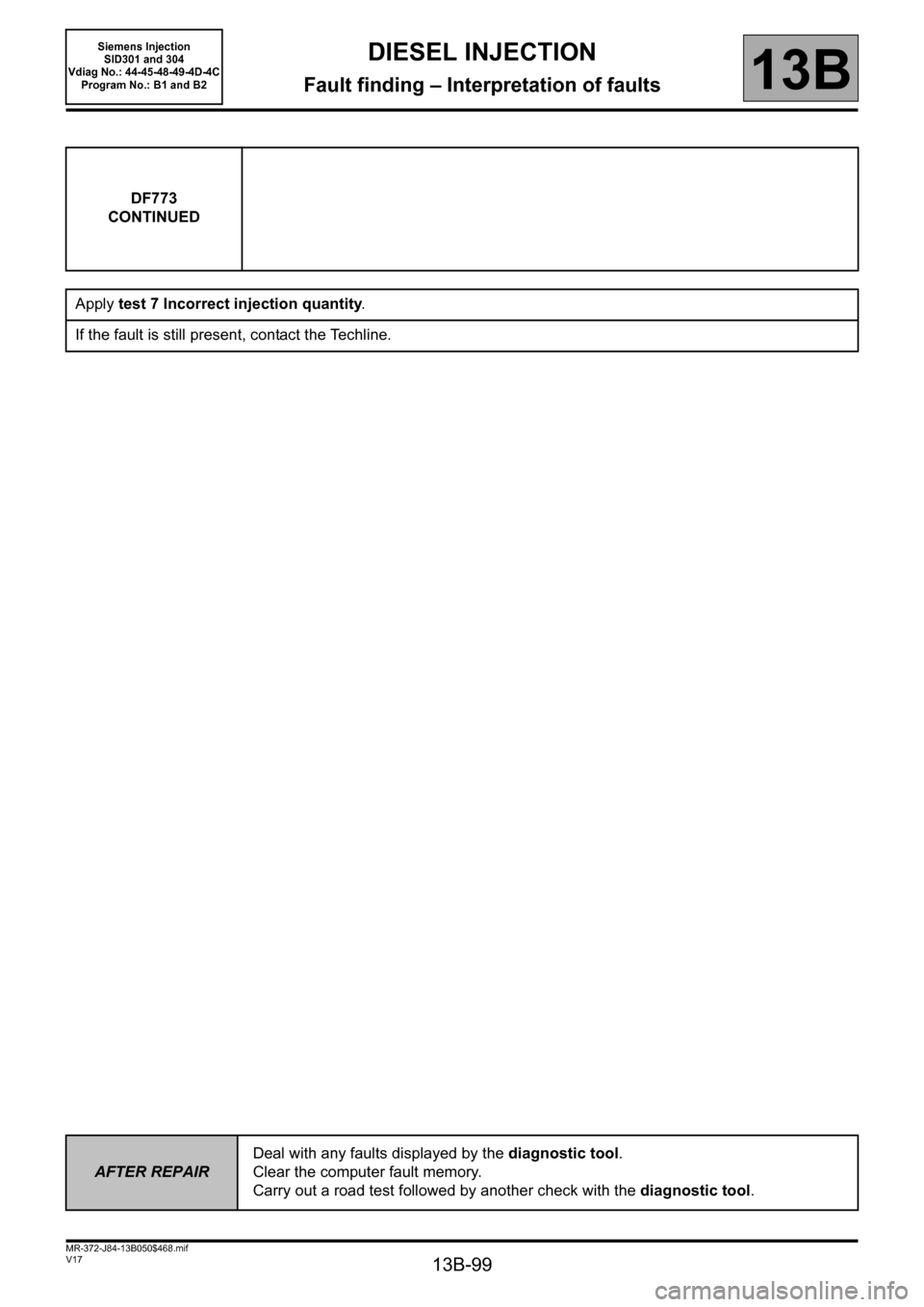
DF773
CONTINUED
Apply test 7 Incorrect injection quantity.
If the fault is still present, contact the Techline.
AFTER REPAIRDeal with any faults displayed by the diagnostic tool.
Clear the computer fault memory.
Carry out a road test followed by another check with the diagnostic tool.
Page 169 of 329

13B-169
MR-372-J84-13B050$624.mif
V17
Siemens Injection
SID301 and 304
Vdiag No.: 44-45-48-49-4D-4C
Program No.: B1 and B2DIESEL INJECTION
Fault finding – Interpretation of statuses13B
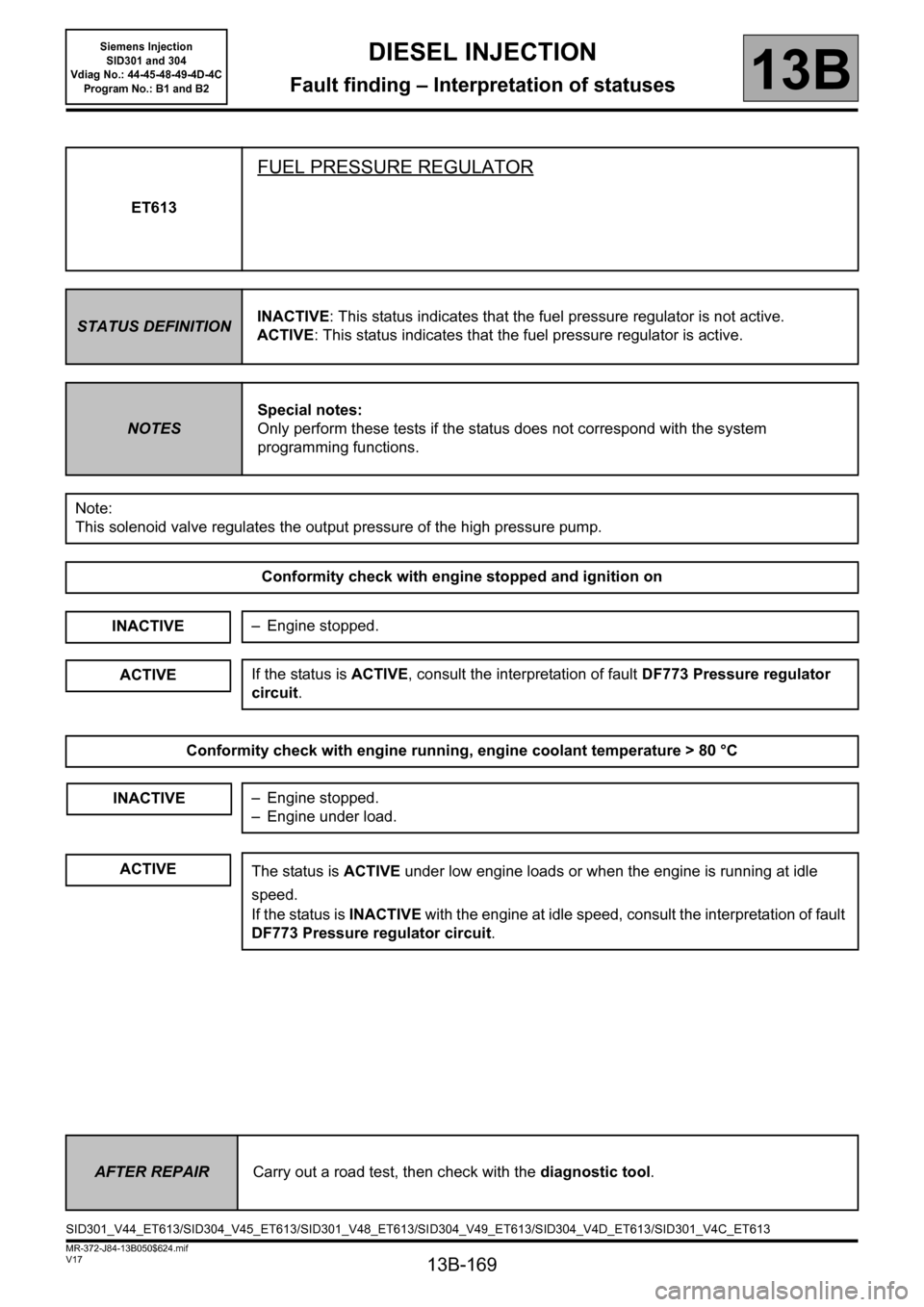
ET613
FUEL PRESSURE REGULATOR
STATUS DEFINITIONINACTIVE: This status indicates that the fuel pressure regulator is not active.
ACTIVE: This status indicates that the fuel pressure regulator is active.
NOTESSpecial notes:
Only perform these tests if the status does not correspond with the system
programming functions.
Note:
This solenoid valve regulates the output pressure of the high pressure pump.
Conformity check with engine stopped and ignition on
INACTIVE
Conformity check with engine running, engine coolant temperature > 80 °C
– Engine stopped.
ACTIVEIf the status is ACTIVE, consult the interpretation of fault DF773 Pressure regulator
circuit.
INACTIVE– Engine stopped.
– Engine under load.
ACTIVEThe status is ACTIVE under low engine loads or when the engine is running at idle
speed.
If the status is INACTIVE with the engine at idle speed, consult the interpretation of fault
DF773 Pressure regulator circuit.
AFTER REPAIRCarry out a road test, then check with the diagnostic tool.
SID301_V44_ET613/SID304_V45_ET613/SID301_V48_ET613/SID304_V49_ET613/SID304_V4D_ET613/SID301_V4C_ET613