Df129 RENAULT SCENIC 2011 J95 / 3.G Engine And Peripherals Siemens Injection Workshop Manual
[x] Cancel search | Manufacturer: RENAULT, Model Year: 2011, Model line: SCENIC, Model: RENAULT SCENIC 2011 J95 / 3.GPages: 329, PDF Size: 1.71 MB
Page 21 of 329
13B-21
MR-372-J84-13B050$195.mif
V17
Siemens Injection
SID301 and 304
Vdiag No.: 44-45-48-49-4D-4C
Program No.: B1 and B2DIESEL INJECTION
Fault finding – Function13B
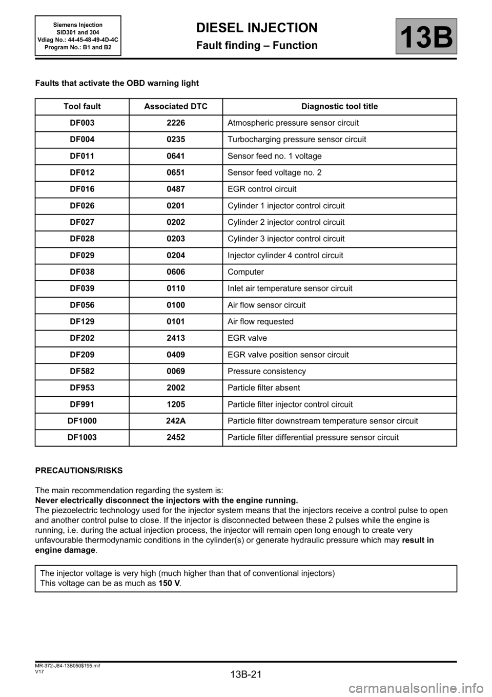
Faults that activate the OBD warning light
PRECAUTIONS/RISKS
The main recommendation regarding the system is:
Never electrically disconnect the injectors with the engine running.
The piezoelectric technology used for the injector system means that the injectors receive a control pulse to open
and another control pulse to close. If the injector is disconnected between these 2 pulses while the engine is
running, i.e. during the actual injection process, the injector will remain open long enough to create very
unfavourable thermodynamic conditions in the cylinder(s) or generate hydraulic pressure which may result in
engine damage. Tool fault Associated DTC Diagnostic tool title
DF003 2226Atmospheric pressure sensor circuit
DF004 0235Turbocharging pressure sensor circuit
DF011 0641Sensor feed no. 1 voltage
DF012 0651Sensor feed voltage no. 2
DF016 0487EGR control circuit
DF026 0201Cylinder 1 injector control circuit
DF027 0202Cylinder 2 injector control circuit
DF028 0203Cylinder 3 injector control circuit
DF029 0204Injector cylinder 4 control circuit
DF038 0606Computer
DF039 0110Inlet air temperature sensor circuit
DF056 0100Air flow sensor circuit
DF129 0101Air flow requested
DF202 2413EGR valve
DF209 0409EGR valve position sensor circuit
DF582 0069Pressure consistency
DF953 2002Particle filter absent
DF991 1205Particle filter injector control circuit
DF1000 242AParticle filter downstream temperature sensor circuit
DF1003 2452Particle filter differential pressure sensor circuit
The injector voltage is very high (much higher than that of conventional injectors)
This voltage can be as much as 150 V.
Page 32 of 329
13B-32
MR-372-J84-13B050$351.mif
V17
Siemens Injection
SID301 and 304
Vdiag No.: 44-45-48-49-4D-4C
Program No.: B1 and B2DIESEL INJECTION
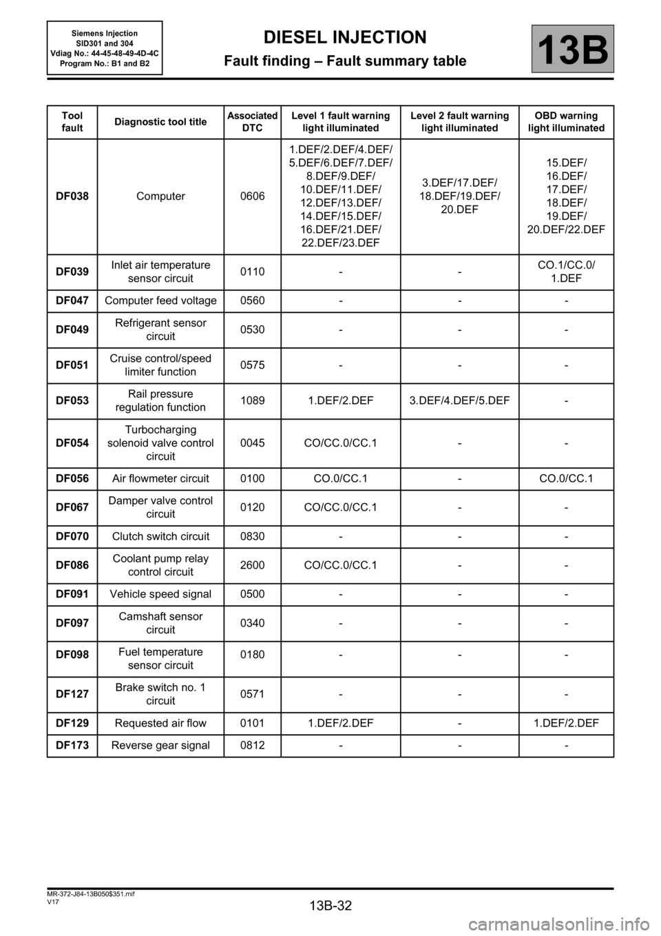
Fault finding – Fault summary table13B
Tool
faultDiagnostic tool titleAssociated
DTCLevel 1 fault warning
light illuminatedLevel 2 fault warning
light illuminatedOBD warning
light illuminated
DF038Computer 06061.DEF/2.DEF/4.DEF/
5.DEF/6.DEF/7.DEF/
8.DEF/9.DEF/
10.DEF/11.DEF/
12.DEF/13.DEF/
14.DEF/15.DEF/
16.DEF/21.DEF/
22.DEF/23.DEF3.DEF/17.DEF/
18.DEF/19.DEF/
20.DEF15.DEF/
16.DEF/
17.DEF/
18.DEF/
19.DEF/
20.DEF/22.DEF
DF039Inlet air temperature
sensor circuit0110 - -CO.1/CC.0/
1.DEF
DF047Computer feed voltage 0560 - - -
DF049Refrigerant sensor
circuit0530 - - -
DF051Cruise control/speed
limiter function0575 - - -
DF053Rail pressure
regulation function1089 1.DEF/2.DEF 3.DEF/4.DEF/5.DEF -
DF054Turbocharging
solenoid valve control
circuit0045 CO/CC.0/CC.1 - -
DF056Air flowmeter circuit 0100 CO.0/CC.1 - CO.0/CC.1
DF067Damper valve control
circuit0120 CO/CC.0/CC.1 - -
DF070Clutch switch circuit 0830 - - -
DF086Coolant pump relay
control circuit2600 CO/CC.0/CC.1 - -
DF091Vehicle speed signal 0500 - - -
DF097Camshaft sensor
circuit0340 - - -
DF098Fuel temperature
sensor circuit0180 - - -
DF127Brake switch no. 1
circuit0571 - - -
DF129Requested air flow 0101 1.DEF/2.DEF - 1.DEF/2.DEF
DF173Reverse gear signal 0812 - - -
Page 72 of 329
13B-72
MR-372-J84-13B050$429.mif
V17
DIESEL INJECTION
Fault finding – Interpretation of faults
Siemens Injection
SID301 and 304
Vdiag No.: 44-45-48-49-4D-4C
Program No.: B1 and B2
13B
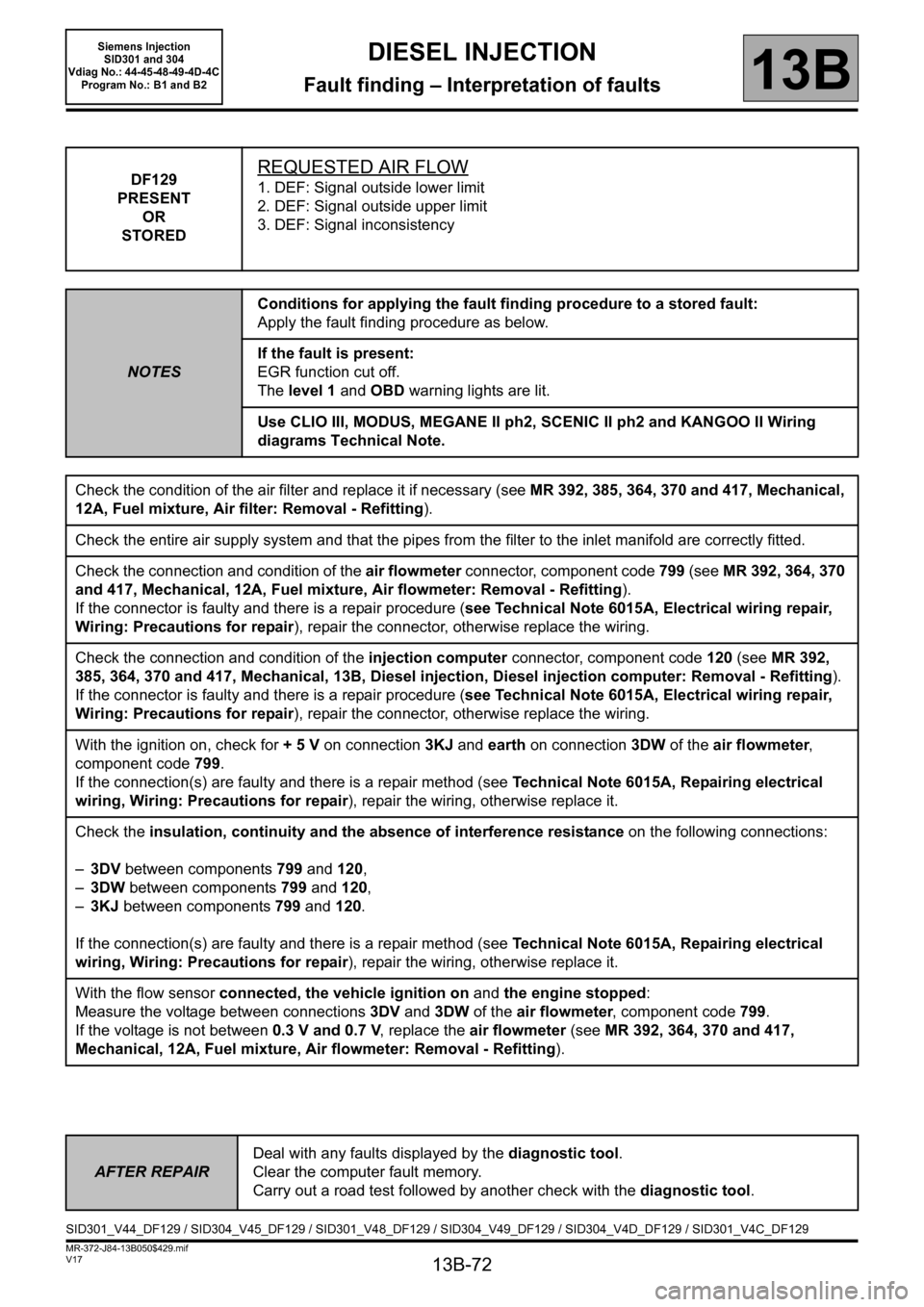
DF129
PRESENT
OR
STOREDREQUESTED AIR FLOW
1. DEF: Signal outside lower limit
2. DEF: Signal outside upper limit
3. DEF: Signal inconsistency
NOTESConditions for applying the fault finding procedure to a stored fault:
Apply the fault finding procedure as below.
If the fault is present:
EGR function cut off.
The level 1 and OBD warning lights are lit.
Use CLIO III, MODUS, MEGANE II ph2, SCENIC II ph2 and KANGOO II Wiring
diagrams Technical Note.
Check the condition of the air filter and replace it if necessary (see MR 392, 385, 364, 370 and 417, Mechanical,
12A, Fuel mixture, Air filter: Removal - Refitting).
Check the entire air supply system and that the pipes from the filter to the inlet manifold are correctly fitted.
Check the connection and condition of the air flowmeter connector, component code 799 (see MR 392, 364, 370
and 417, Mechanical, 12A, Fuel mixture, Air flowmeter: Removal - Refitting).
If the connector is faulty and there is a repair procedure (see Technical Note 6015A, Electrical wiring repair,
Wiring: Precautions for repair), repair the connector, otherwise replace the wiring.
Check the connection and condition of the injection computer connector, component code 120 (see MR 392,
385, 364, 370 and 417, Mechanical, 13B, Diesel injection, Diesel injection computer: Removal - Refitting).
If the connector is faulty and there is a repair procedure (see Technical Note 6015A, Electrical wiring repair,
Wiring: Precautions for repair), repair the connector, otherwise replace the wiring.
With the ignition on, check for + 5 V on connection 3KJ and earth on connection 3DW of the air flowmeter,
component code 799.
If the connection(s) are faulty and there is a repair method (see Technical Note 6015A, Repairing electrical
wiring, Wiring: Precautions for repair), repair the wiring, otherwise replace it.
Check the insulation, continuity and the absence of interference resistance on the following connections:
–3DV between components 799 and 120,
–3DW between components 799 and 120,
–3KJ between components 799 and 120.
If the connection(s) are faulty and there is a repair method (see Technical Note 6015A, Repairing electrical
wiring, Wiring: Precautions for repair), repair the wiring, otherwise replace it.
With the flow sensor connected, the vehicle ignition on and the engine stopped:
Measure the voltage between connections 3DV and 3DW of the air flowmeter, component code 799.
If the voltage is not between 0.3 V and 0.7 V, replace the air flowmeter (see MR 392, 364, 370 and 417,
Mechanical, 12A, Fuel mixture, Air flowmeter: Removal - Refitting).
AFTER REPAIRDeal with any faults displayed by the diagnostic tool.
Clear the computer fault memory.
Carry out a road test followed by another check with the diagnostic tool.
SID301_V44_DF129 / SID304_V45_DF129 / SID301_V48_DF129 / SID304_V49_DF129 / SID304_V4D_DF129 / SID301_V4C_DF129
Page 278 of 329
13B-278
MR-372-J84-13B050$897.mif
V17
DIESEL INJECTION
Fault finding – Fault Finding Chart
Siemens Injection
SID301 and 304
Vdiag No.: 44-45-48-49-4D-4C
Program No.: B1 and B2
13B
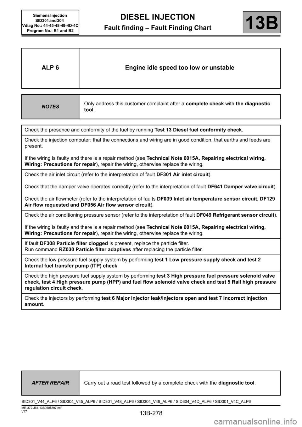
ALP 6 Engine idle speed too low or unstable
NOTESOnly address this customer complaint after a complete check with the diagnostic
tool.
Check the presence and conformity of the fuel by running Test 13 Diesel fuel conformity check.
Check the injection computer: that the connections and wiring are in good condition, that earths and feeds are
present.
If the wiring is faulty and there is a repair method (see Technical Note 6015A, Repairing electrical wiring,
Wiring: Precautions for repair), repair the wiring, otherwise replace the wiring.
Check the air inlet circuit (refer to the interpretation of fault DF301 Air inlet circuit).
Check that the damper valve operates correctly (refer to the interpretation of fault DF641 Damper valve circuit).
Check the air flowmeter (refer to the interpretation of faults DF039 Inlet air temperature sensor circuit, DF129
Air flow requested and DF056 Air flow sensor circuit).
Check the air conditioning pressure sensor (refer to the interpretation of fault DF049 Refrigerant sensor circuit).
If the wiring is faulty and there is a repair method (see Technical Note 6015A, Repairing electrical wiring,
Wiring: Precautions for repair), repair the wiring, otherwise replace the wiring.
If fault DF308 Particle filter clogged is present, replace the particle filter.
Run command RZ030 Particle filter adaptives after replacing the particle filter.
Check the low pressure fuel supply system by performing test 1 Low pressure supply check and test 2
Internal fuel transfer pump (ITP) check.
Check the high pressure fuel supply system by performing test 3 High pressure fuel pressure solenoid valve
check, test 4 High pressure pump (HPP) and fuel flow solenoid valve check and test 5 Rail high pressure
regulation circuit check.
Check the injectors by performing test 6 Major injector leak/injectors open and test 7 Incorrect injection
amount.
AFTER REPAIRCarry out a road test followed by a complete check with the diagnostic tool.
SID301_V44_ALP6 / SID304_V45_ALP6 / SID301_V48_ALP6 / SID304_V49_ALP6 / SID304_V4D_ALP6 / SID301_V4C_ALP6
Page 279 of 329
13B-279
MR-372-J84-13B050$897.mif
V17
DIESEL INJECTION
Fault finding – Fault Finding Chart
Siemens Injection
SID301 and 304
Vdiag No.: 44-45-48-49-4D-4C
Program No.: B1 and B2
13B
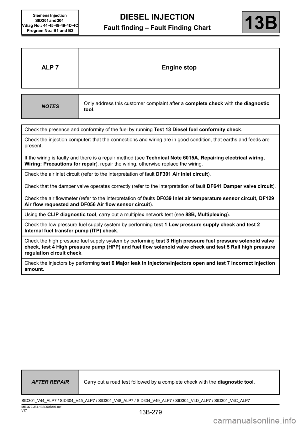
ALP 7 Engine stop
NOTESOnly address this customer complaint after a complete check with the diagnostic
tool.
Check the presence and conformity of the fuel by running Test 13 Diesel fuel conformity check.
Check the injection computer: that the connections and wiring are in good condition, that earths and feeds are
present.
If the wiring is faulty and there is a repair method (see Technical Note 6015A, Repairing electrical wiring,
Wiring: Precautions for repair), repair the wiring, otherwise replace the wiring.
Check the air inlet circuit (refer to the interpretation of fault DF301 Air inlet circuit).
Check that the damper valve operates correctly (refer to the interpretation of fault DF641 Damper valve circuit).
Check the air flowmeter (refer to the interpretation of faults DF039 Inlet air temperature sensor circuit, DF129
Air flow requested and DF056 Air flow sensor circuit).
Using the CLIP diagnostic tool, carry out a multiplex network test (see 88B, Multiplexing).
Check the low pressure fuel supply system by performing test 1 Low pressure supply check and test 2
Internal fuel transfer pump (ITP) check.
Check the high pressure fuel supply system by performing test 3 High pressure fuel pressure solenoid valve
check, test 4 High pressure pump (HPP) and fuel flow solenoid valve check and test 5 Rail high pressure
regulation circuit check.
Check the injectors by performing test 6 Major leak in injectors/injectors open and test 7 Incorrect injection
amount.
AFTER REPAIRCarry out a road test followed by a complete check with the diagnostic tool.
SID301_V44_ALP7 / SID304_V45_ALP7 / SID301_V48_ALP7 / SID304_V49_ALP7 / SID304_V4D_ALP7 / SID301_V4C_ALP7
Page 280 of 329
13B-280
MR-372-J84-13B050$897.mif
V17
DIESEL INJECTION
Fault finding – Fault Finding Chart
Siemens Injection
SID301 and 304
Vdiag No.: 44-45-48-49-4D-4C
Program No.: B1 and B2
13B
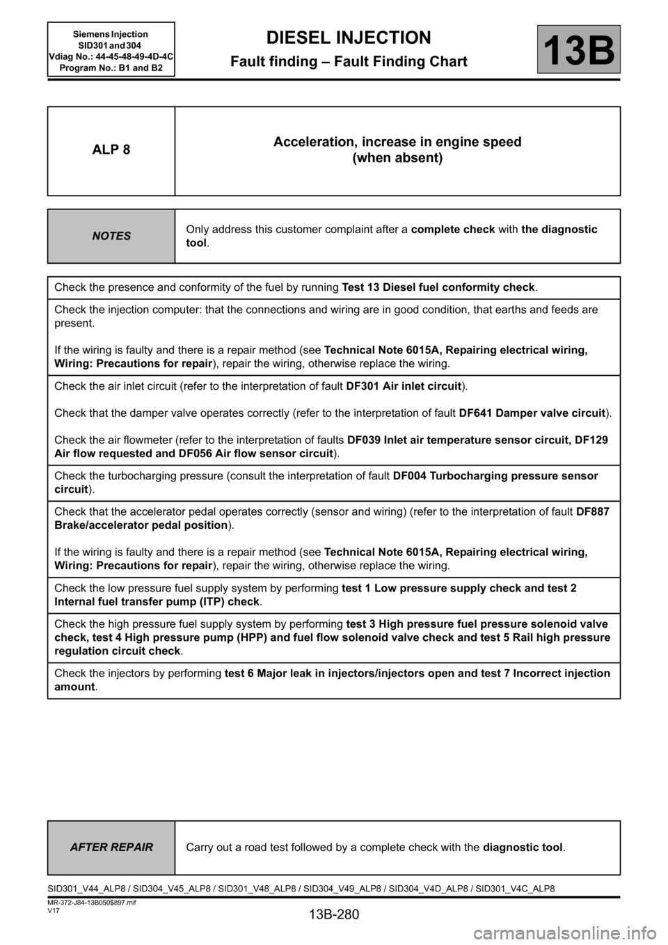
ALP 8Acceleration, increase in engine speed
(when absent)
NOTESOnly address this customer complaint after a complete check with the diagnostic
tool.
Check the presence and conformity of the fuel by running Test 13 Diesel fuel conformity check.
Check the injection computer: that the connections and wiring are in good condition, that earths and feeds are
present.
If the wiring is faulty and there is a repair method (see Technical Note 6015A, Repairing electrical wiring,
Wiring: Precautions for repair), repair the wiring, otherwise replace the wiring.
Check the air inlet circuit (refer to the interpretation of fault DF301 Air inlet circuit).
Check that the damper valve operates correctly (refer to the interpretation of fault DF641 Damper valve circuit).
Check the air flowmeter (refer to the interpretation of faults DF039 Inlet air temperature sensor circuit, DF129
Air flow requested and DF056 Air flow sensor circuit).
Check the turbocharging pressure (consult the interpretation of fault DF004 Turbocharging pressure sensor
circuit).
Check that the accelerator pedal operates correctly (sensor and wiring) (refer to the interpretation of fault DF887
Brake/accelerator pedal position).
If the wiring is faulty and there is a repair method (see Technical Note 6015A, Repairing electrical wiring,
Wiring: Precautions for repair), repair the wiring, otherwise replace the wiring.
Check the low pressure fuel supply system by performing test 1 Low pressure supply check and test 2
Internal fuel transfer pump (ITP) check.
Check the high pressure fuel supply system by performing test 3 High pressure fuel pressure solenoid valve
check, test 4 High pressure pump (HPP) and fuel flow solenoid valve check and test 5 Rail high pressure
regulation circuit check.
Check the injectors by performing test 6 Major leak in injectors/injectors open and test 7 Incorrect injection
amount.
AFTER REPAIRCarry out a road test followed by a complete check with the diagnostic tool.
SID301_V44_ALP8 / SID304_V45_ALP8 / SID301_V48_ALP8 / SID304_V49_ALP8 / SID304_V4D_ALP8 / SID301_V4C_ALP8
Page 281 of 329
13B-281
MR-372-J84-13B050$897.mif
V17
DIESEL INJECTION
Fault finding – Fault Finding Chart
Siemens Injection
SID301 and 304
Vdiag No.: 44-45-48-49-4D-4C
Program No.: B1 and B2
13B
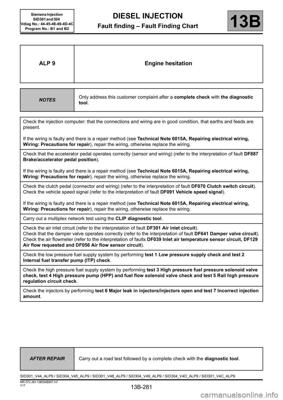
ALP 9 Engine hesitation
NOTESOnly address this customer complaint after a complete check with the diagnostic
tool.
Check the injection computer: that the connections and wiring are in good condition, that earths and feeds are
present.
If the wiring is faulty and there is a repair method (see Technical Note 6015A, Repairing electrical wiring,
Wiring: Precautions for repair), repair the wiring, otherwise replace the wiring.
Check that the accelerator pedal operates correctly (sensor and wiring) (refer to the interpretation of fault DF887
Brake/accelerator pedal position).
If the wiring is faulty and there is a repair method (see Technical Note 6015A, Repairing electrical wiring,
Wiring: Precautions for repair), repair the wiring, otherwise replace the wiring.
Check the clutch pedal (connector and wiring) (refer to the interpretation of fault DF070 Clutch switch circuit).
Check the vehicle speed signal (refer to the interpretation of fault DF091 Vehicle speed signal).
If the wiring is faulty and there is a repair method (see Technical Note 6015A, Repairing electrical wiring,
Wiring: Precautions for repair), repair the wiring, otherwise replace the wiring.
Carry out a multiplex network test using the CLIP diagnostic tool.
Check the air inlet circuit (refer to the interpretation of fault DF301 Air inlet circuit).
Check that the damper valve operates correctly (refer to the interpretation of fault DF641 Damper valve circuit).
Check the air flowmeter (refer to the interpretation of faults DF039 Inlet air temperature sensor circuit, DF129
Air flow requested and DF056 Air flow sensor circuit).
Check the low pressure fuel supply system by performing test 1 Low pressure supply check and test 2
Internal fuel transfer pump (ITP) check.
Check the high pressure fuel supply system by performing test 3 High pressure fuel pressure solenoid valve
check, test 4 High pressure pump (HPP) and fuel flow solenoid valve check and test 5 Rail high pressure
regulation circuit check.
Check the injectors by performing test 6 Major leak in injectors/injectors open and test 7 Incorrect injection
amount.
AFTER REPAIRCarry out a road test followed by a complete check with the diagnostic tool.
SID301_V44_ALP9 / SID304_V45_ALP9 / SID301_V48_ALP9 / SID304_V49_ALP9 / SID304_V4D_ALP9 / SID301_V4C_ALP9
Page 284 of 329
13B-284
MR-372-J84-13B050$897.mif
V17
DIESEL INJECTION
Fault finding – Fault Finding Chart
Siemens Injection
SID301 and 304
Vdiag No.: 44-45-48-49-4D-4C
Program No.: B1 and B2
13B
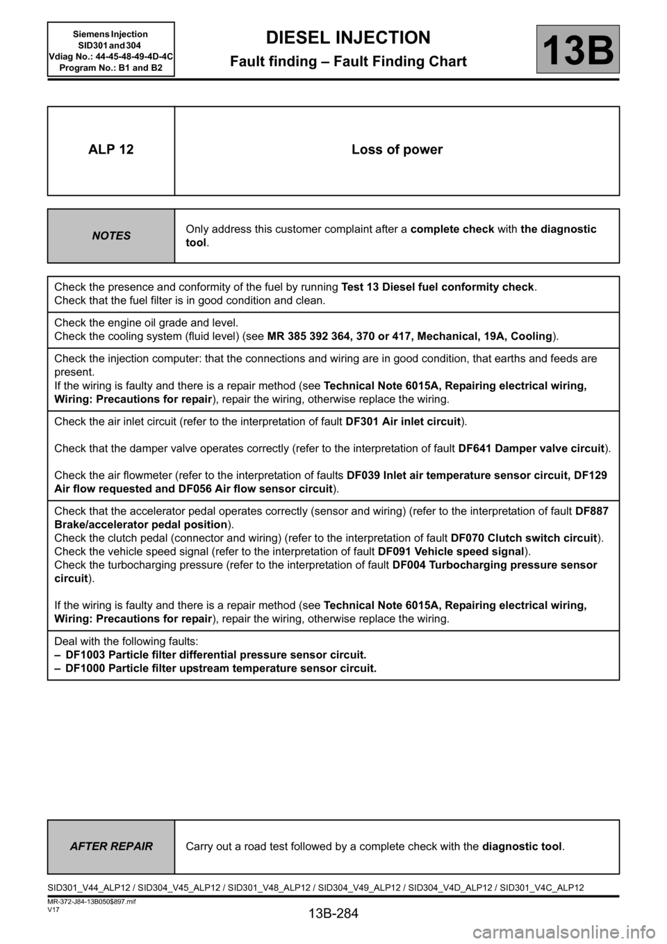
ALP 12 Loss of power
NOTESOnly address this customer complaint after a complete check with the diagnostic
tool.
Check the presence and conformity of the fuel by running Test 13 Diesel fuel conformity check.
Check that the fuel filter is in good condition and clean.
Check the engine oil grade and level.
Check the cooling system (fluid level) (see MR 385 392 364, 370 or 417, Mechanical, 19A, Cooling).
Check the injection computer: that the connections and wiring are in good condition, that earths and feeds are
present.
If the wiring is faulty and there is a repair method (see Technical Note 6015A, Repairing electrical wiring,
Wiring: Precautions for repair), repair the wiring, otherwise replace the wiring.
Check the air inlet circuit (refer to the interpretation of fault DF301 Air inlet circuit).
Check that the damper valve operates correctly (refer to the interpretation of fault DF641 Damper valve circuit).
Check the air flowmeter (refer to the interpretation of faults DF039 Inlet air temperature sensor circuit, DF129
Air flow requested and DF056 Air flow sensor circuit).
Check that the accelerator pedal operates correctly (sensor and wiring) (refer to the interpretation of fault DF887
Brake/accelerator pedal position).
Check the clutch pedal (connector and wiring) (refer to the interpretation of fault DF070 Clutch switch circuit).
Check the vehicle speed signal (refer to the interpretation of fault DF091 Vehicle speed signal).
Check the turbocharging pressure (refer to the interpretation of fault DF004 Turbocharging pressure sensor
circuit).
If the wiring is faulty and there is a repair method (see Technical Note 6015A, Repairing electrical wiring,
Wiring: Precautions for repair), repair the wiring, otherwise replace the wiring.
Deal with the following faults:
– DF1003 Particle filter differential pressure sensor circuit.
– DF1000 Particle filter upstream temperature sensor circuit.
AFTER REPAIRCarry out a road test followed by a complete check with the diagnostic tool.
SID301_V44_ALP12 / SID304_V45_ALP12 / SID301_V48_ALP12 / SID304_V49_ALP12 / SID304_V4D_ALP12 / SID301_V4C_ALP12
Page 288 of 329
13B-288
MR-372-J84-13B050$897.mif
V17
DIESEL INJECTION
Fault finding – Fault Finding Chart
Siemens Injection
SID301 and 304
Vdiag No.: 44-45-48-49-4D-4C
Program No.: B1 and B2
13B
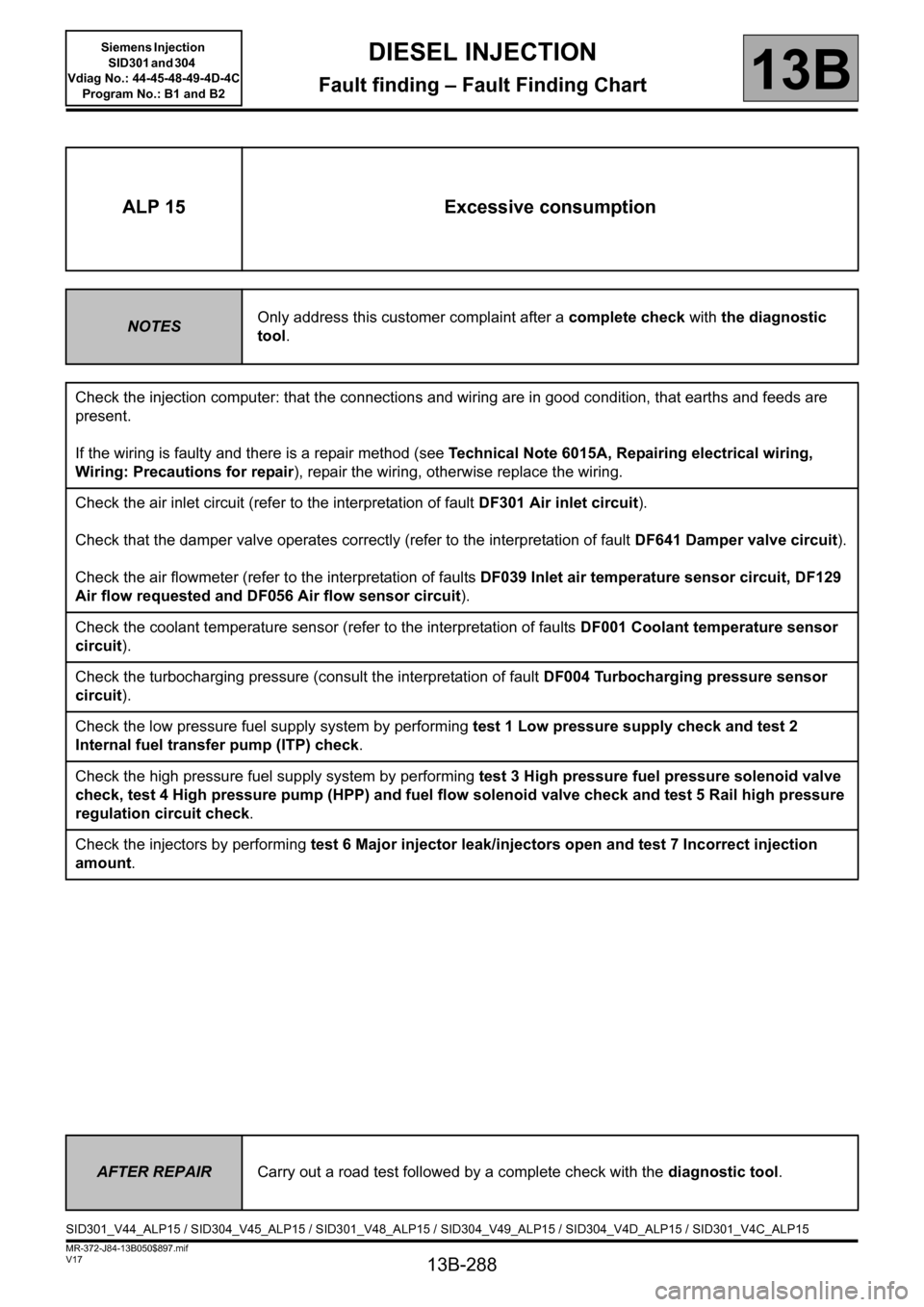
ALP 15 Excessive consumption
NOTESOnly address this customer complaint after a complete check with the diagnostic
tool.
Check the injection computer: that the connections and wiring are in good condition, that earths and feeds are
present.
If the wiring is faulty and there is a repair method (see Technical Note 6015A, Repairing electrical wiring,
Wiring: Precautions for repair), repair the wiring, otherwise replace the wiring.
Check the air inlet circuit (refer to the interpretation of fault DF301 Air inlet circuit).
Check that the damper valve operates correctly (refer to the interpretation of fault DF641 Damper valve circuit).
Check the air flowmeter (refer to the interpretation of faults DF039 Inlet air temperature sensor circuit, DF129
Air flow requested and DF056 Air flow sensor circuit).
Check the coolant temperature sensor (refer to the interpretation of faults DF001 Coolant temperature sensor
circuit).
Check the turbocharging pressure (consult the interpretation of fault DF004 Turbocharging pressure sensor
circuit).
Check the low pressure fuel supply system by performing test 1 Low pressure supply check and test 2
Internal fuel transfer pump (ITP) check.
Check the high pressure fuel supply system by performing test 3 High pressure fuel pressure solenoid valve
check, test 4 High pressure pump (HPP) and fuel flow solenoid valve check and test 5 Rail high pressure
regulation circuit check.
Check the injectors by performing test 6 Major injector leak/injectors open and test 7 Incorrect injection
amount.
AFTER REPAIRCarry out a road test followed by a complete check with the diagnostic tool.
SID301_V44_ALP15 / SID304_V45_ALP15 / SID301_V48_ALP15 / SID304_V49_ALP15 / SID304_V4D_ALP15 / SID301_V4C_ALP15
Page 290 of 329
13B-290
MR-372-J84-13B050$897.mif
V17
DIESEL INJECTION
Fault finding – Fault Finding Chart
Siemens Injection
SID301 and 304
Vdiag No.: 44-45-48-49-4D-4C
Program No.: B1 and B2
13B
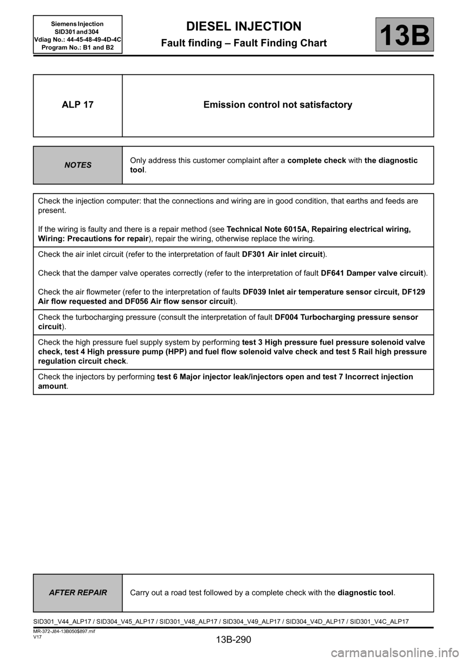
ALP 17 Emission control not satisfactory
NOTESOnly address this customer complaint after a complete check with the diagnostic
tool.
Check the injection computer: that the connections and wiring are in good condition, that earths and feeds are
present.
If the wiring is faulty and there is a repair method (see Technical Note 6015A, Repairing electrical wiring,
Wiring: Precautions for repair), repair the wiring, otherwise replace the wiring.
Check the air inlet circuit (refer to the interpretation of fault DF301 Air inlet circuit).
Check that the damper valve operates correctly (refer to the interpretation of fault DF641 Damper valve circuit).
Check the air flowmeter (refer to the interpretation of faults DF039 Inlet air temperature sensor circuit, DF129
Air flow requested and DF056 Air flow sensor circuit).
Check the turbocharging pressure (consult the interpretation of fault DF004 Turbocharging pressure sensor
circuit).
Check the high pressure fuel supply system by performing test 3 High pressure fuel pressure solenoid valve
check, test 4 High pressure pump (HPP) and fuel flow solenoid valve check and test 5 Rail high pressure
regulation circuit check.
Check the injectors by performing test 6 Major injector leak/injectors open and test 7 Incorrect injection
amount.
AFTER REPAIRCarry out a road test followed by a complete check with the diagnostic tool.
SID301_V44_ALP17 / SID304_V45_ALP17 / SID301_V48_ALP17 / SID304_V49_ALP17 / SID304_V4D_ALP17 / SID301_V4C_ALP17