coolant level RENAULT SCENIC 2011 J95 / 3.G Engine And Peripherals Siemens Injection Workshop Manual
[x] Cancel search | Manufacturer: RENAULT, Model Year: 2011, Model line: SCENIC, Model: RENAULT SCENIC 2011 J95 / 3.GPages: 329, PDF Size: 1.71 MB
Page 13 of 329
13B-13
MR-372-J84-13B050$195.mif
V17
13B
DIESEL INJECTION
Fault finding – Function
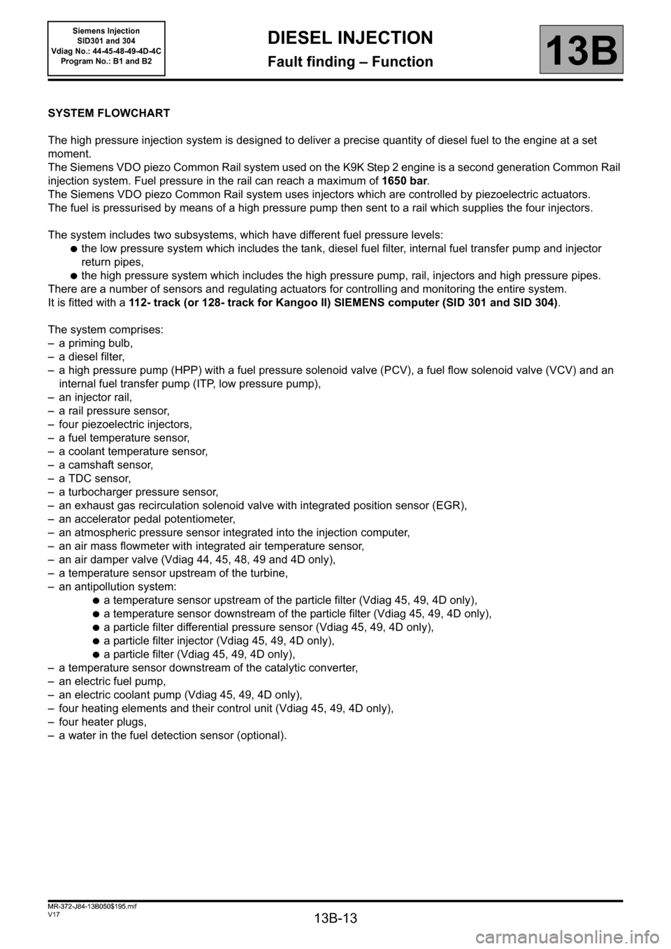
SYSTEM FLOWCHART
The high pressure injection system is designed to deliver a precise quantity of diesel fuel to the engine at a set
moment.
The Siemens VDO piezo Common Rail system used on the K9K Step 2 engine is a second generation Common Rail
injection system. Fuel pressure in the rail can reach a maximum of 1650 bar.
The Siemens VDO piezo Common Rail system uses injectors which are controlled by piezoelectric actuators.
The fuel is pressurised by means of a high pressure pump then sent to a rail which supplies the four injectors.
The system includes two subsystems, which have different fuel pressure levels:
●the low pressure system which includes the tank, diesel fuel filter, internal fuel transfer pump and injector
return pipes,
●the high pressure system which includes the high pressure pump, rail, injectors and high pressure pipes.
There are a number of sensors and regulating actuators for controlling and monitoring the entire system.
It is fitted with a 112- track (or 128- track for Kangoo II) SIEMENS computer (SID 301 and SID 304).
The system comprises:
– a priming bulb,
– a diesel filter,
– a high pressure pump (HPP) with a fuel pressure solenoid valve (PCV), a fuel flow solenoid valve (VCV) and an
internal fuel transfer pump (ITP, low pressure pump),
– an injector rail,
– a rail pressure sensor,
– four piezoelectric injectors,
– a fuel temperature sensor,
– a coolant temperature sensor,
– a camshaft sensor,
– a TDC sensor,
– a turbocharger pressure sensor,
– an exhaust gas recirculation solenoid valve with integrated position sensor (EGR),
– an accelerator pedal potentiometer,
– an atmospheric pressure sensor integrated into the injection computer,
– an air mass flowmeter with integrated air temperature sensor,
– an air damper valve (Vdiag 44, 45, 48, 49 and 4D only),
– a temperature sensor upstream of the turbine,
– an antipollution system:
●a temperature sensor upstream of the particle filter (Vdiag 45, 49, 4D only),
●a temperature sensor downstream of the particle filter (Vdiag 45, 49, 4D only),
●a particle filter differential pressure sensor (Vdiag 45, 49, 4D only),
●a particle filter injector (Vdiag 45, 49, 4D only),
●a particle filter (Vdiag 45, 49, 4D only),
– a temperature sensor downstream of the catalytic converter,
– an electric fuel pump,
– an electric coolant pump (Vdiag 45, 49, 4D only),
– four heating elements and their control unit (Vdiag 45, 49, 4D only),
– four heater plugs,
– a water in the fuel detection sensor (optional).
MR-372-J84-13B050$195.mif
Siemens Injection
SID301 and 304
Vdiag No.: 44-45-48-49-4D-4C
Program No.: B1 and B2
Page 19 of 329
13B-19
MR-372-J84-13B050$195.mif
V17
Siemens Injection
SID301 and 304
Vdiag No.: 44-45-48-49-4D-4C
Program No.: B1 and B2DIESEL INJECTION
Fault finding – Function13B
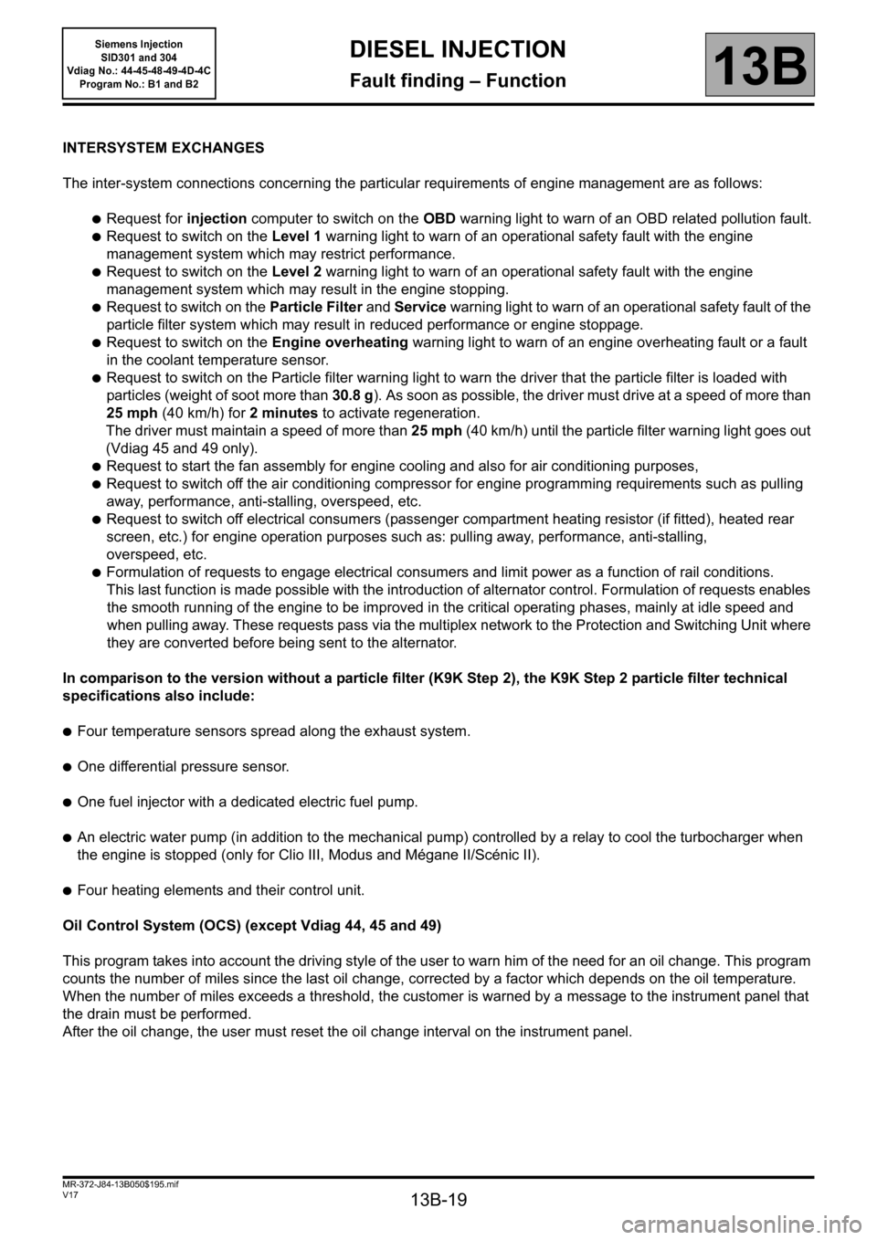
INTERSYSTEM EXCHANGES
The inter-system connections concerning the particular requirements of engine management are as follows:
●Request for injection computer to switch on the OBD warning light to warn of an OBD related pollution fault.
●Request to switch on the Level 1 warning light to warn of an operational safety fault with the engine
management system which may restrict performance.
●Request to switch on the Level 2 warning light to warn of an operational safety fault with the engine
management system which may result in the engine stopping.
●Request to switch on the Particle Filter and Service warning light to warn of an operational safety fault of the
particle filter system which may result in reduced performance or engine stoppage.
●Request to switch on the Engine overheating warning light to warn of an engine overheating fault or a fault
in the coolant temperature sensor.
●Request to switch on the Particle filter warning light to warn the driver that the particle filter is loaded with
particles (weight of soot more than 30.8 g). As soon as possible, the driver must drive at a speed of more than
25 mph (40 km/h) for 2 minutes to activate regeneration.
The driver must maintain a speed of more than 25 mph (40 km/h) until the particle filter warning light goes out
(Vdiag 45 and 49 only).
●Request to start the fan assembly for engine cooling and also for air conditioning purposes,
●Request to switch off the air conditioning compressor for engine programming requirements such as pulling
away, performance, anti-stalling, overspeed, etc.
●Request to switch off electrical consumers (passenger compartment heating resistor (if fitted), heated rear
screen, etc.) for engine operation purposes such as: pulling away, performance, anti-stalling,
overspeed, etc.
●Formulation of requests to engage electrical consumers and limit power as a function of rail conditions.
This last function is made possible with the introduction of alternator control. Formulation of requests enables
the smooth running of the engine to be improved in the critical operating phases, mainly at idle speed and
when pulling away. These requests pass via the multiplex network to the Protection and Switching Unit where
they are converted before being sent to the alternator.
In comparison to the version without a particle filter (K9K Step 2), the K9K Step 2 particle filter technical
specifications also include:
●Four temperature sensors spread along the exhaust system.
●One differential pressure sensor.
●One fuel injector with a dedicated electric fuel pump.
●An electric water pump (in addition to the mechanical pump) controlled by a relay to cool the turbocharger when
the engine is stopped (only for Clio III, Modus and Mégane II/Scénic II).
●Four heating elements and their control unit.
Oil Control System (OCS) (except Vdiag 44, 45 and 49)
This program takes into account the driving style of the user to warn him of the need for an oil change. This program
counts the number of miles since the last oil change, corrected by a factor which depends on the oil temperature.
When the number of miles exceeds a threshold, the customer is warned by a message to the instrument panel that
the drain must be performed.
After the oil change, the user must reset the oil change interval on the instrument panel.
Page 24 of 329
13B-24
MR-372-J84-13B050$195.mif
V17
Siemens Injection
SID301 and 304
Vdiag No.: 44-45-48-49-4D-4C
Program No.: B1 and B2DIESEL INJECTION
Fault finding – Function13B
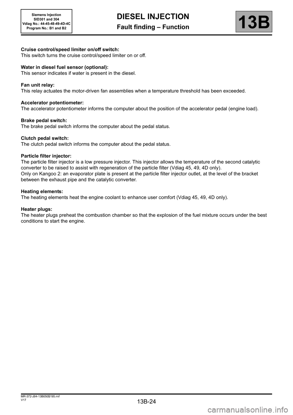
Cruise control/speed limiter on/off switch:
This switch turns the cruise control/speed limiter on or off.
Water in diesel fuel sensor (optional):
This sensor indicates if water is present in the diesel.
Fan unit relay:
This relay actuates the motor-driven fan assemblies when a temperature threshold has been exceeded.
Accelerator potentiometer:
The accelerator potentiometer informs the computer about the position of the accelerator pedal (engine load).
Brake pedal switch:
The brake pedal switch informs the computer about the pedal status.
Clutch pedal switch:
The clutch pedal switch informs the computer about the pedal status.
Particle filter injector:
The particle filter injector is a low pressure injector. This injector allows the temperature of the second catalytic
converter to be raised to assist with regeneration of the particle filter (Vdiag 45, 49, 4D only).
Only on Kangoo 2: an evaporator plate is present at the particle filter injector outlet, at the level of the bracket
between the exhaust pipe and the catalytic converter.
Heating elements:
The heating elements heat the engine coolant to enhance user comfort (Vdiag 45, 49, 4D only).
Heater plugs:
The heater plugs preheat the combustion chamber so that the explosion of the fuel mixture occurs under the best
conditions to start the engine.
Page 31 of 329
13B-31
MR-372-J84-13B050$351.mif
V17
13B
DIESEL INJECTION
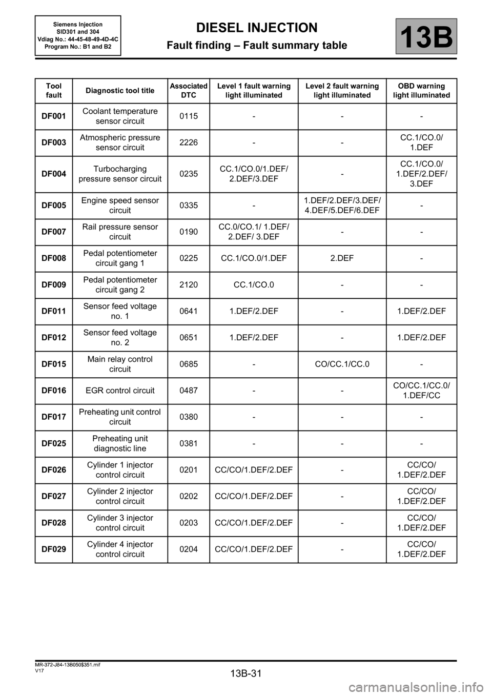
Fault finding – Fault summary table
Tool
faultDiagnostic tool titleAssociated
DTCLevel 1 fault warning
light illuminatedLevel 2 fault warning
light illuminatedOBD warning
light illuminated
DF001Coolant temperature
sensor circuit0115 - - -
DF003Atmospheric pressure
sensor circuit2226 - -CC.1/CO.0/
1.DEF
DF004Turbocharging
pressure sensor circuit0235CC.1/CO.0/1.DEF/
2.DEF/3.DEF-CC.1/CO.0/
1.DEF/2.DEF/
3.DEF
DF005Engine speed sensor
circuit0335 -1.DEF/2.DEF/3.DEF/
4.DEF/5.DEF/6.DEF-
DF007Rail pressure sensor
circuit0190CC.0/CO.1/ 1.DEF/
2.DEF/ 3.DEF--
DF008Pedal potentiometer
circuit gang 10225 CC.1/CO.0/1.DEF 2.DEF -
DF009Pedal potentiometer
circuit gang 22120 CC.1/CO.0 - -
DF011Sensor feed voltage
no. 10641 1.DEF/2.DEF - 1.DEF/2.DEF
DF012Sensor feed voltage
no. 20651 1.DEF/2.DEF - 1.DEF/2.DEF
DF015Main relay control
circuit0685 - CO/CC.1/CC.0 -
DF016EGR control circuit 0487 - -CO/CC.1/CC.0/
1.DEF/CC
DF017Preheating unit control
circuit0380 - - -
DF025Preheating unit
diagnostic line0381 - - -
DF026Cylinder 1 injector
control circuit0201 CC/CO/1.DEF/2.DEF -CC/CO/
1.DEF/2.DEF
DF027Cylinder 2 injector
control circuit0202 CC/CO/1.DEF/2.DEF -CC/CO/
1.DEF/2.DEF
DF028Cylinder 3 injector
control circuit0203 CC/CO/1.DEF/2.DEF -CC/CO/
1.DEF/2.DEF
DF029Cylinder 4 injector
control circuit0204 CC/CO/1.DEF/2.DEF -CC/CO/
1.DEF/2.DEF
MR-372-J84-13B050$351.mif
Siemens Injection
SID301 and 304
Vdiag No.: 44-45-48-49-4D-4C
Program No.: B1 and B2
Page 32 of 329
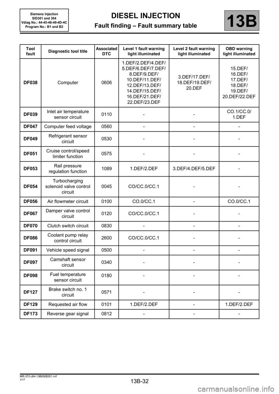
13B-32
MR-372-J84-13B050$351.mif
V17
Siemens Injection
SID301 and 304
Vdiag No.: 44-45-48-49-4D-4C
Program No.: B1 and B2DIESEL INJECTION
Fault finding – Fault summary table13B
Tool
faultDiagnostic tool titleAssociated
DTCLevel 1 fault warning
light illuminatedLevel 2 fault warning
light illuminatedOBD warning
light illuminated
DF038Computer 06061.DEF/2.DEF/4.DEF/
5.DEF/6.DEF/7.DEF/
8.DEF/9.DEF/
10.DEF/11.DEF/
12.DEF/13.DEF/
14.DEF/15.DEF/
16.DEF/21.DEF/
22.DEF/23.DEF3.DEF/17.DEF/
18.DEF/19.DEF/
20.DEF15.DEF/
16.DEF/
17.DEF/
18.DEF/
19.DEF/
20.DEF/22.DEF
DF039Inlet air temperature
sensor circuit0110 - -CO.1/CC.0/
1.DEF
DF047Computer feed voltage 0560 - - -
DF049Refrigerant sensor
circuit0530 - - -
DF051Cruise control/speed
limiter function0575 - - -
DF053Rail pressure
regulation function1089 1.DEF/2.DEF 3.DEF/4.DEF/5.DEF -
DF054Turbocharging
solenoid valve control
circuit0045 CO/CC.0/CC.1 - -
DF056Air flowmeter circuit 0100 CO.0/CC.1 - CO.0/CC.1
DF067Damper valve control
circuit0120 CO/CC.0/CC.1 - -
DF070Clutch switch circuit 0830 - - -
DF086Coolant pump relay
control circuit2600 CO/CC.0/CC.1 - -
DF091Vehicle speed signal 0500 - - -
DF097Camshaft sensor
circuit0340 - - -
DF098Fuel temperature
sensor circuit0180 - - -
DF127Brake switch no. 1
circuit0571 - - -
DF129Requested air flow 0101 1.DEF/2.DEF - 1.DEF/2.DEF
DF173Reverse gear signal 0812 - - -
Page 135 of 329
13B-135
MR-372-J84-13B050$585.mif
V17
Siemens Injection
SID301 and 304
Vdiag No.: 44-45-48-49-4D-4C
Program No.: B1 and B2DIESEL INJECTION
Fault finding – Interpretation of statuses13B
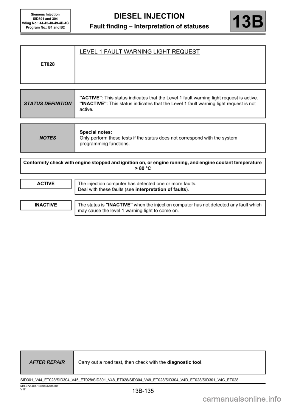
ET028
LEVEL 1 FAULT WARNING LIGHT REQUEST
STATUS DEFINITION"ACTIVE": This status indicates that the Level 1 fault warning light request is active.
"INACTIVE": This status indicates that the Level 1 fault warning light request is not
active.
NOTESSpecial notes:
Only perform these tests if the status does not correspond with the system
programming functions.
Conformity check with engine stopped and ignition on, or engine running, and engine coolant temperature
>80 °C
ACTIVE
The injection computer has detected one or more faults.
Deal with these faults (see interpretation of faults).
INACTIVEThe status is "INACTIVE" when the injection computer has not detected any fault which
may cause the level 1 warning light to come on.
AFTER REPAIRCarry out a road test, then check with the diagnostic tool.
SID301_V44_ET028/SID304_V45_ET028/SID301_V48_ET028/SID304_V49_ET028/SID304_V4D_ET028/SID301_V4C_ET028
Page 136 of 329
13B-136
MR-372-J84-13B050$585.mif
V17
Siemens Injection
SID301 and 304
Vdiag No.: 44-45-48-49-4D-4C
Program No.: B1 and B2DIESEL INJECTION
Fault finding – Interpretation of statuses13B
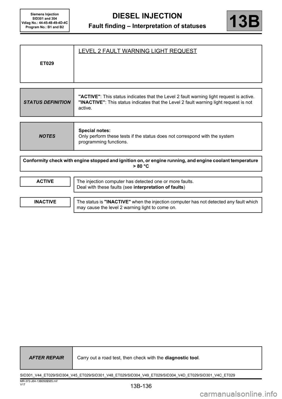
ET029
LEVEL 2 FAULT WARNING LIGHT REQUEST
STATUS DEFINITION"ACTIVE": This status indicates that the Level 2 fault warning light request is active.
"INACTIVE": This status indicates that the Level 2 fault warning light request is not
active.
NOTESSpecial notes:
Only perform these tests if the status does not correspond with the system
programming functions.
Conformity check with engine stopped and ignition on, or engine running, and engine coolant temperature
>80 °C
ACTIVE
The injection computer has detected one or more faults.
Deal with these faults (see interpretation of faults)
INACTIVEThe status is "INACTIVE" when the injection computer has not detected any fault which
may cause the level 2 warning light to come on.
AFTER REPAIRCarry out a road test, then check with the diagnostic tool.
SID301_V44_ET029/SID304_V45_ET029/SID301_V48_ET029/SID304_V49_ET029/SID304_V4D_ET029/SID301_V4C_ET029
Page 151 of 329
13B-151
MR-372-J84-13B050$585.mif
V17
DIESEL INJECTION
Fault finding – Interpretation of statuses
Siemens Injection
SID301 and 304
Vdiag No.: 44-45-48-49-4D-4C
Program No.: B1 and B2
13B
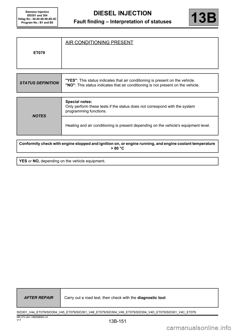
ET079
AIR CONDITIONING PRESENT
STATUS DEFINITION"YES": This status indicates that air conditioning is present on the vehicle.
"NO": This status indicates that air conditioning is not present on the vehicle.
NOTESSpecial notes:
Only perform these tests if the status does not correspond with the system
programming functions.
Heating and air conditioning is present depending on the vehicle's equipment level.
Conformity check with engine stopped and ignition on, or engine running, and engine coolant temperature
>80 °C
YES or NO, depending on the vehicle equipment.
AFTER REPAIRCarry out a road test, then check with the diagnostic tool.
SID301_V44_ET079/SID304_V45_ET079/SID301_V48_ET079/SID304_V49_ET079/SID304_V4D_ET079/SID301_V4C_ET079
Page 239 of 329
13B-239
MR-372-J84-13B050$780.mif
V17
DIESEL INJECTION
Fault finding – Interpretation of parameters
Siemens Injection
SID301 and 304
Vdiag No.: 44-45-48-49-4D-4C
Program No.: B1 and B2
13B
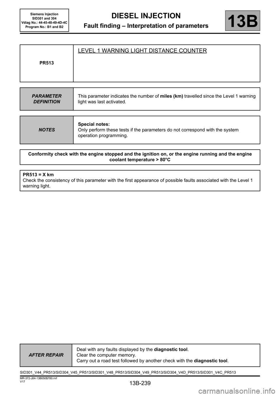
PR513
LEVEL 1 WARNING LIGHT DISTANCE COUNTER
PARAMETER
DEFINITIONThis parameter indicates the number of miles (km) travelled since the Level 1 warning
light was last activated.
NOTESSpecial notes:
Only perform these tests if the parameters do not correspond with the system
operation programming.
Conformity check with the engine stopped and the ignition on, or the engine running and the engine
coolant temperature > 80°C
PR513 = X km
Check the consistency of this parameter with the first appearance of possible faults associated with the Level 1
warning light.
AFTER REPAIRDeal with any faults displayed by the diagnostic tool.
Clear the computer memory.
Carry out a road test followed by another check with the diagnostic tool.
SID301_V44_PR513/SID304_V45_PR513/SID301_V48_PR513/SID304_V49_PR513/SID304_V4D_PR513/SID301_V4C_PR513
Page 240 of 329
13B-240
MR-372-J84-13B050$780.mif
V17
DIESEL INJECTION
Fault finding – Interpretation of parameters
Siemens Injection
SID301 and 304
Vdiag No.: 44-45-48-49-4D-4C
Program No.: B1 and B2
13B
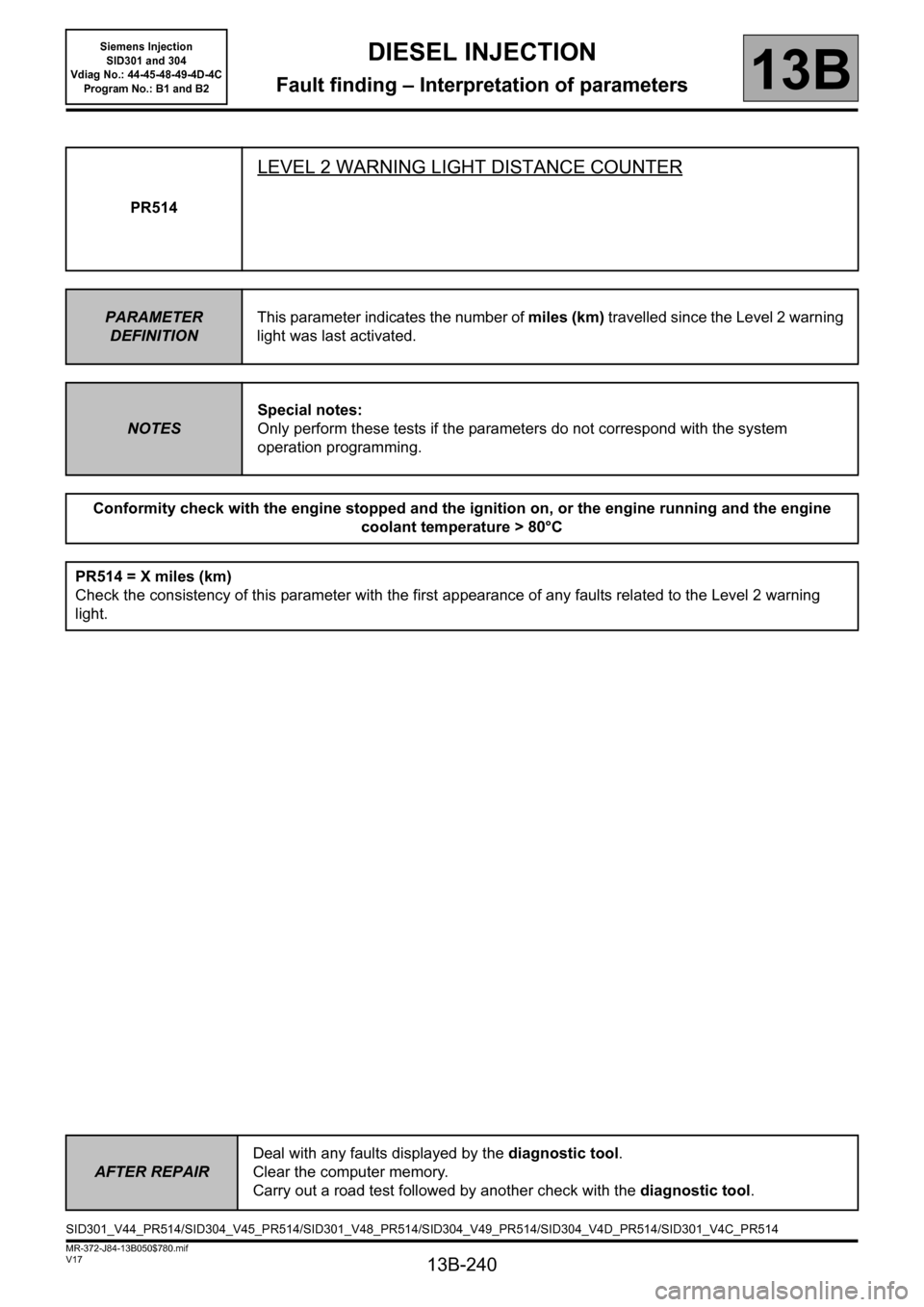
PR514
LEVEL 2 WARNING LIGHT DISTANCE COUNTER
PARAMETER
DEFINITIONThis parameter indicates the number of miles (km) travelled since the Level 2 warning
light was last activated.
NOTESSpecial notes:
Only perform these tests if the parameters do not correspond with the system
operation programming.
Conformity check with the engine stopped and the ignition on, or the engine running and the engine
coolant temperature > 80°C
PR514 = X miles (km)
Check the consistency of this parameter with the first appearance of any faults related to the Level 2 warning
light.
AFTER REPAIRDeal with any faults displayed by the diagnostic tool.
Clear the computer memory.
Carry out a road test followed by another check with the diagnostic tool.
SID301_V44_PR514/SID304_V45_PR514/SID301_V48_PR514/SID304_V49_PR514/SID304_V4D_PR514/SID301_V4C_PR514