fuel type RENAULT SCENIC 2011 J95 / 3.G Engine And Peripherals Siemens Injection Workshop Manual
[x] Cancel search | Manufacturer: RENAULT, Model Year: 2011, Model line: SCENIC, Model: RENAULT SCENIC 2011 J95 / 3.GPages: 329, PDF Size: 1.71 MB
Page 20 of 329
13B-20
MR-372-J84-13B050$195.mif
V17
Siemens Injection
SID301 and 304
Vdiag No.: 44-45-48-49-4D-4C
Program No.: B1 and B2DIESEL INJECTION
Fault finding – Function13B
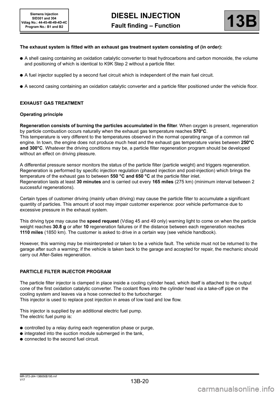
The exhaust system is fitted with an exhaust gas treatment system consisting of (in order):
●A shell casing containing an oxidation catalytic converter to treat hydrocarbons and carbon monoxide, the volume
and positioning of which is identical to K9K Step 2 without a particle filter.
●A fuel injector supplied by a second fuel circuit which is independent of the main fuel circuit.
●A second casing containing an oxidation catalytic converter and a particle filter positioned under the vehicle floor.
EXHAUST GAS TREATMENT
Operating principle
Regeneration consists of burning the particles accumulated in the filter. When oxygen is present, regeneration
by particle combustion occurs naturally when the exhaust gas temperature reaches 570°C.
This temperature is very different to the temperatures observed in the normal operating range of a common rail
engine. In town, the engine does not produce much heat and the exhaust gas temperature varies between 250°C
and 300°C. Whatever the driving conditions may be, a particle filter regeneration program should be developed
without an effect on driving pleasure.
A differential pressure sensor monitors the status of the particle filter (particle weight) and triggers regeneration.
Regeneration is performed by specific injection regulation (phased injection and post-injection) which brings the
temperature of the exhaust gas to between 550 °C and 650 °C at the particle filter inlet.
Regeneration lasts at least 30 minutes and is carried out every 165 miles (275 km) (minimum interval between 2
successful regenerations).
Certain types of customer driving (mainly urban driving) may cause the particle filter to accumulate a significant
quantity of particles. This amount of soot may impair customer experience: poor vehicle performance due to
excessive pressure in the exhaust system.
This driving type may cause the speed request (Vdiag 45 and 49 only) warning light to come on when the particle
weight reaches 30.8 g or after 10 regeneration failures or if the distance between each regeneration reaches
111 0 m il es (1850 km). The customer is asked to drive in a certain way (see vehicle handbook).
However, this warning may be misinterpreted or taken to be a vehicle fault. The vehicle must not be returned to the
garage after such a warning; if the vehicle is taken back to the garage and accepted for repair, the mechanic should
carry out After-Sales regeneration.
PARTICLE FILTER INJECTOR PROGRAM
The particle filter injector is clamped in place inside a cooling cylinder head, which itself is attached to the output
cone of the first oxidation catalytic converter. The coolant flows into the cylinder head via a take-off pipe on the
cooling system and leaves via a hose connected to the turbocharger.
This injector is used to replace post injection in areas of low load and low flow.
This injector is supplied by an additional electric fuel pump.
The electric fuel pump is:
●controlled by a relay during each regeneration phase or purge,
●integrated into the suction module submerged in the tank,
●connected to the second fuel circuit.
Page 30 of 329
13B-30
MR-372-J84-13B050$312.mif
V17
13B
DIESEL INJECTION
Fault finding – Configurations and programming
SPECIAL COMMANDS
SC001: Write saved data.
Use this command after replacing or (re)programming the computer (if the data has been saved using command
SC003).
SC003: Save computer data.
This command enables the computer operating data, the engine adaptives, to be recorded.
Use this command before replacing or (re)programming a computer.
SC013: Enter VIN.
This command permits manual entry of the vehicle's VIN into the computer.
Use this command each time the computer is replaced or (re)programmed.
SC017: Particle filter regeneration.
The regeneration command is used to burn particles which have accumulated in the filter.
Run this command when the particle filter is clogged.
SC040: Speed limiter (Kangoo II only).
This command enables the vehicle's speed to be restricted to a certain speed.
Use this command at the customer's request.
SC041: Modification of the commercial vehicle idle speed (Kangoo II only).
This command enables the idle speed for vehicles such as refrigerated vehicles, ambulances etc. to be increased or
decreased.
CONFIGURATION READING
LC005: Gearbox type.
Manual gearbox or automatic transmission/sequential gearbox
LC009: Air conditioning.
With or without.
LC065: Water in diesel fuel sensor.
With or without.
LC120: Cruise control.
With or without.
LC121: Speed limiter.
With or without.
MR-372-J84-13B050$312.mif
Siemens Injection
SID301 and 304
Vdiag No.: 44-45-48-49-4D-4C
Program No.: B1 and B2
Page 85 of 329
13B-85
MR-372-J84-13B050$429.mif
V17
DIESEL INJECTION
Fault finding – Interpretation of faults
Siemens Injection
SID301 and 304
Vdiag No.: 44-45-48-49-4D-4C
Program No.: B1 and B2
13B
*diff: differential
*temp: temperatureDF308
PRESENT
OR
STORED
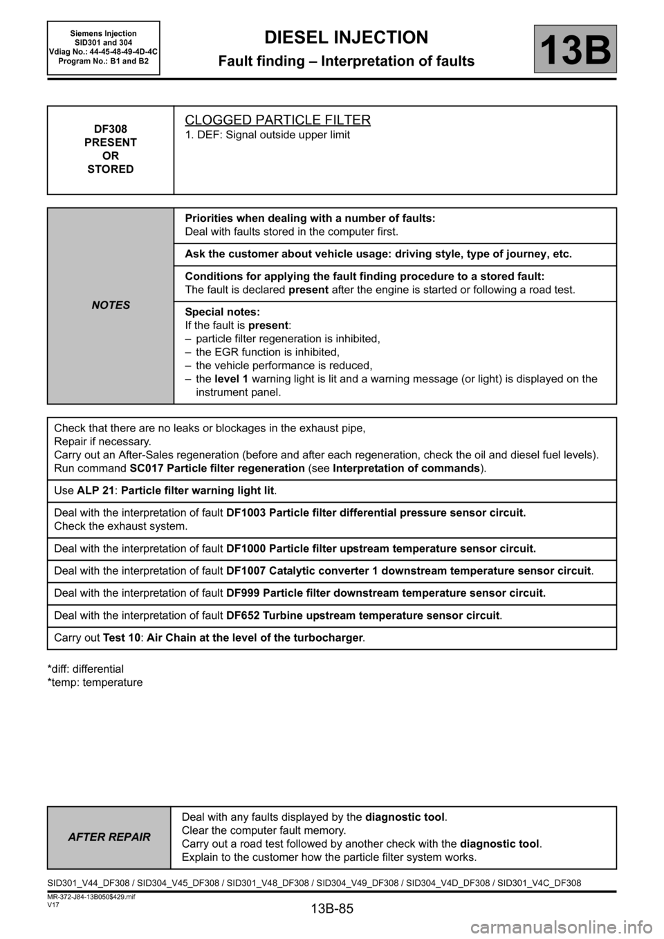
CLOGGED PARTICLE FILTER
1. DEF: Signal outside upper limit
NOTESPriorities when dealing with a number of faults:
Deal with faults stored in the computer first.
Ask the customer about vehicle usage: driving style, type of journey, etc.
Conditions for applying the fault finding procedure to a stored fault:
The fault is declared present after the engine is started or following a road test.
Special notes:
If the fault is present:
– particle filter regeneration is inhibited,
– the EGR function is inhibited,
– the vehicle performance is reduced,
– the level 1 warning light is lit and a warning message (or light) is displayed on the
instrument panel.
Check that there are no leaks or blockages in the exhaust pipe,
Repair if necessary.
Carry out an After-Sales regeneration (before and after each regeneration, check the oil and diesel fuel levels).
Run command SC017 Particle filter regeneration (see Interpretation of commands).
Use ALP 21: Particle filter warning light lit.
Deal with the interpretation of fault DF1003 Particle filter differential pressure sensor circuit.
Check the exhaust system.
Deal with the interpretation of fault DF1000 Particle filter upstream temperature sensor circuit.
Deal with the interpretation of fault DF1007 Catalytic converter 1 downstream temperature sensor circuit.
Deal with the interpretation of fault DF999 Particle filter downstream temperature sensor circuit.
Deal with the interpretation of fault DF652 Turbine upstream temperature sensor circuit.
Carry out Te s t 1 0: Air Chain at the level of the turbocharger.
AFTER REPAIRDeal with any faults displayed by the diagnostic tool.
Clear the computer fault memory.
Carry out a road test followed by another check with the diagnostic tool.
Explain to the customer how the particle filter system works.
SID301_V44_DF308 / SID304_V45_DF308 / SID301_V48_DF308 / SID304_V49_DF308 / SID304_V4D_DF308 / SID301_V4C_DF308
Page 293 of 329
13B-293
MR-372-J84-13B050$897.mif
V17
Siemens Injection
SID301 and 304
Vdiag No.: 44-45-48-49-4D-4C
Program No.: B1 and B2DIESEL INJECTION
Fault finding – Fault Finding Chart13B
NOTighten the interface
or the concerned pipe.
End of procedure.
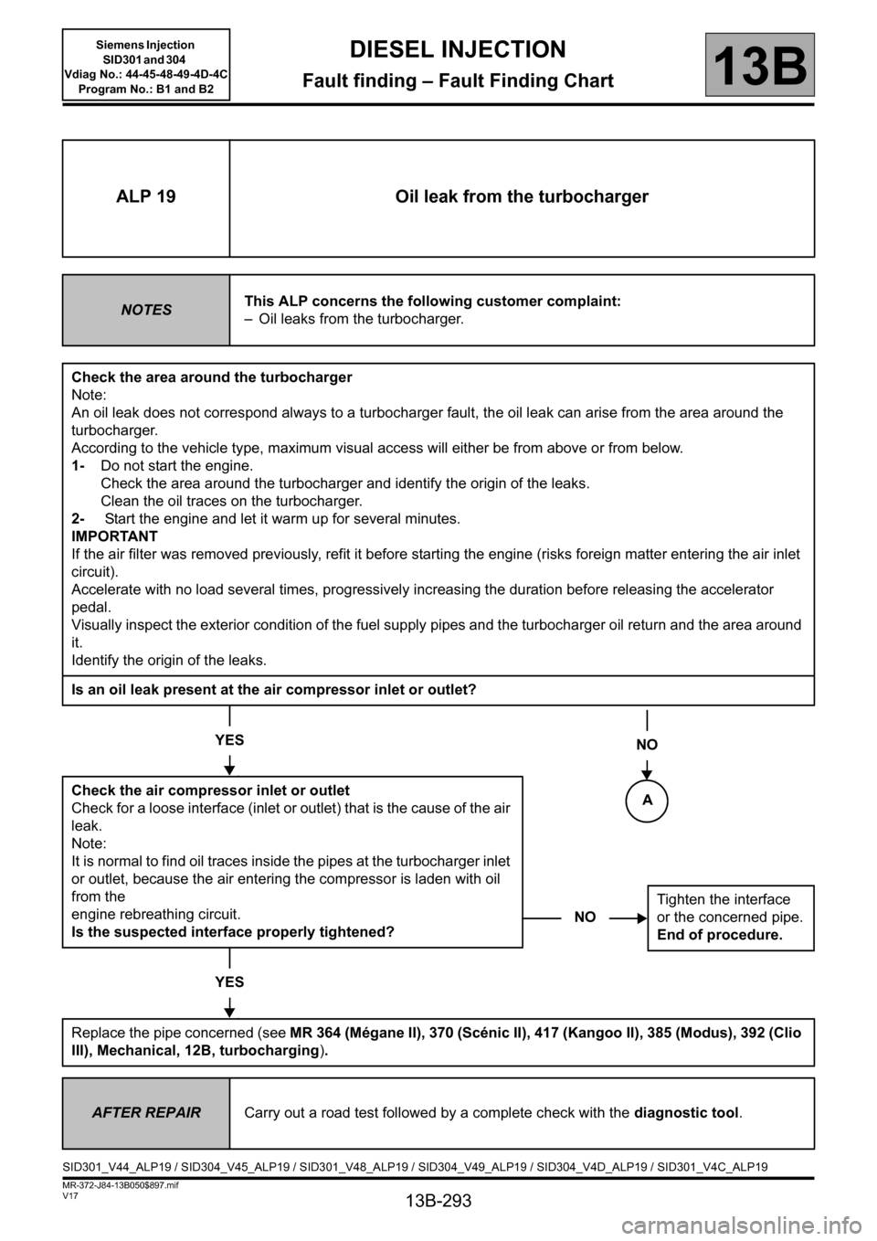
ALP 19 Oil leak from the turbocharger
NOTESThis ALP concerns the following customer complaint:
– Oil leaks from the turbocharger.
Check the area around the turbocharger
Note:
An oil leak does not correspond always to a turbocharger fault, the oil leak can arise from the area around the
turbocharger.
According to the vehicle type, maximum visual access will either be from above or from below.
1-Do not start the engine.
Check the area around the turbocharger and identify the origin of the leaks.
Clean the oil traces on the turbocharger.
2- Start the engine and let it warm up for several minutes.
IMPORTANT
If the air filter was removed previously, refit it before starting the engine (risks foreign matter entering the air inlet
circuit).
Accelerate with no load several times, progressively increasing the duration before releasing the accelerator
pedal.
Visually inspect the exterior condition of the fuel supply pipes and the turbocharger oil return and the area around
it.
Identify the origin of the leaks.
Is an oil leak present at the air compressor inlet or outlet?
YES
Check the air compressor inlet or outlet
Check for a loose interface (inlet or outlet) that is the cause of the air
leak.
Note:
It is normal to find oil traces inside the pipes at the turbocharger inlet
or outlet, because the air entering the compressor is laden with oil
from the
engine rebreathing circuit.
Is the suspected interface properly tightened?
YES
Replace the pipe concerned (see MR 364 (Mégane II), 370 (Scénic II), 417 (Kangoo II), 385 (Modus), 392 (Clio
III), Mechanical, 12B, turbocharging).
NO
AFTER REPAIRCarry out a road test followed by a complete check with the diagnostic tool.
SID301_V44_ALP19 / SID304_V45_ALP19 / SID301_V48_ALP19 / SID304_V49_ALP19 / SID304_V4D_ALP19 / SID301_V4C_ALP19
A
Page 325 of 329
13B-325
MR-372-J84-13B050$936.mif
V17
DIESEL INJECTION
Fault finding – Tests13B
Siemens Injection
SID301 and 304
Vdiag No.: 44-45-48-49-4D-4C
Program No.: B1 and B2
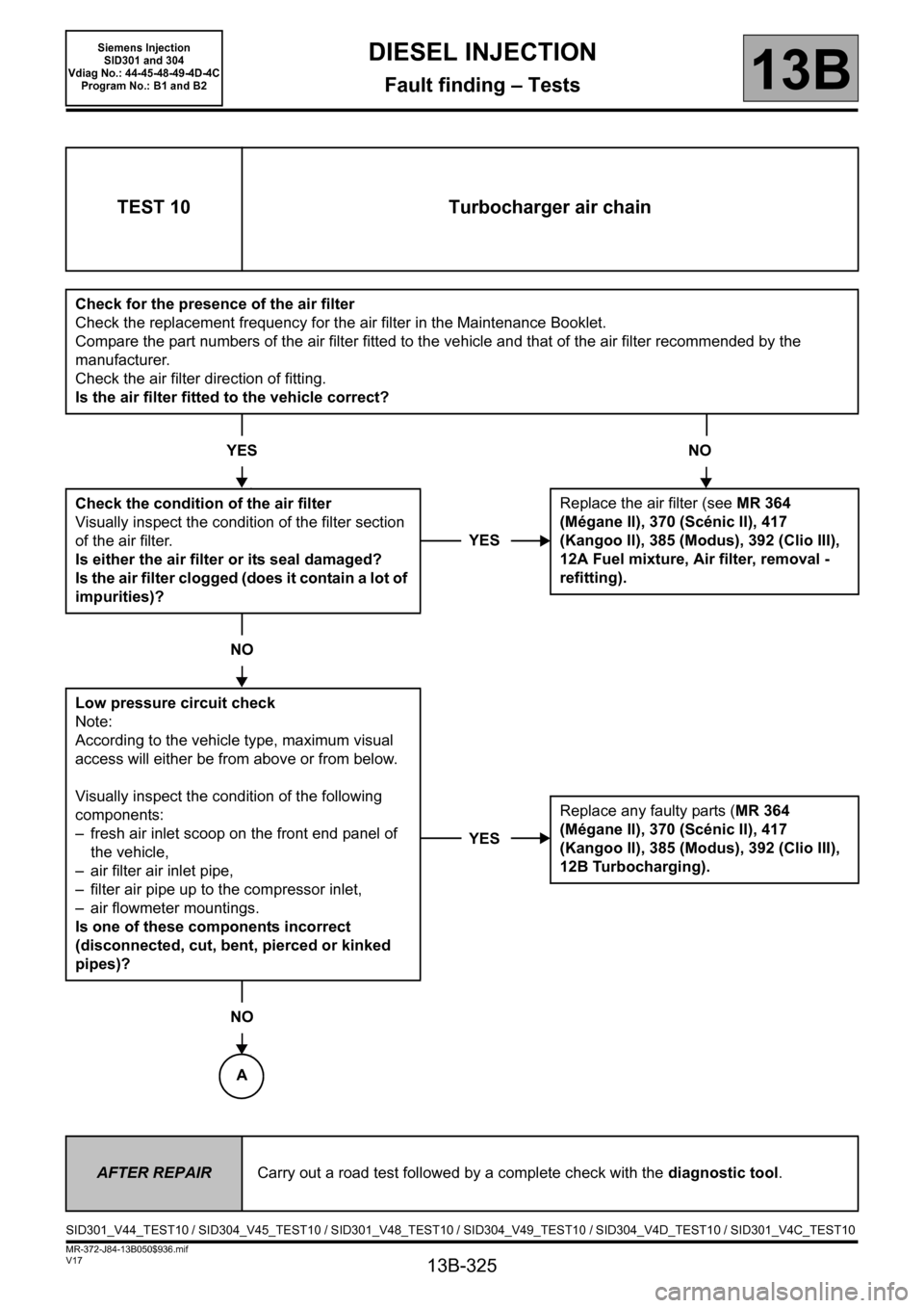
TEST 10 Turbocharger air chain
Check for the presence of the air filter
Check the replacement frequency for the air filter in the Maintenance Booklet.
Compare the part numbers of the air filter fitted to the vehicle and that of the air filter recommended by the
manufacturer.
Check the air filter direction of fitting.
Is the air filter fitted to the vehicle correct?
YES NO
Check the condition of the air filter
Visually inspect the condition of the filter section
of the air filter.
Is either the air filter or its seal damaged?
Is the air filter clogged (does it contain a lot of
impurities)?
NO
Low pressure circuit check
Note:
According to the vehicle type, maximum visual
access will either be from above or from below.
Visually inspect the condition of the following
components:
– fresh air inlet scoop on the front end panel of
the vehicle,
– air filter air inlet pipe,
– filter air pipe up to the compressor inlet,
– air flowmeter mountings.
Is one of these components incorrect
(disconnected, cut, bent, pierced or kinked
pipes)?
NO
YESReplace the air filter (see MR 364
(Mégane II), 370 (Scénic II), 417
(Kangoo II), 385 (Modus), 392 (Clio III),
12A Fuel mixture, Air filter, removal -
refitting).
YESReplace any faulty parts (MR 364
(Mégane II), 370 (Scénic II), 417
(Kangoo II), 385 (Modus), 392 (Clio III),
12B Turbocharging).
AFTER REPAIRCarry out a road test followed by a complete check with the diagnostic tool.
SID301_V44_TEST10 / SID304_V45_TEST10 / SID301_V48_TEST10 / SID304_V49_TEST10 / SID304_V4D_TEST10 / SID301_V4C_TEST10
A
Page 327 of 329
13B-327
MR-372-J84-13B050$975.mif
V17
DIESEL INJECTION
Fault finding – Tests13B
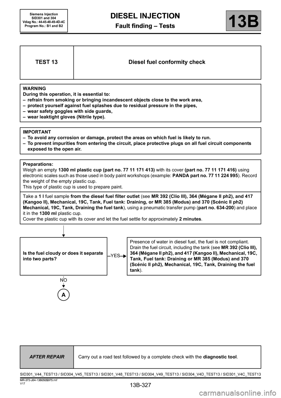
TEST 13 Diesel fuel conformity check
WARNING
During this operation, it is essential to:
– refrain from smoking or bringing incandescent objects close to the work area,
– protect yourself against fuel splashes due to residual pressure in the pipes,
– wear safety goggles with side guards,
– wear leaktight gloves (Nitrile type).
IMPORTANT
– To avoid any corrosion or damage, protect the areas on which fuel is likely to run.
– To prevent impurities from entering the circuit, place protective plugs on all fuel circuit components
exposed to the open air.
Preparations:
Weigh an empty 1300 ml plastic cup (part no. 77 11 171 413) with its cover (part no. 77 11 171 416) using
electronic scales such as those used in body paint workshops (example: PANDA part no. 77 11 224 995). Record
the weight of the empty plastic cup.
This type of plastic cup is used to prepare paint.
Take a 1 l fuel sample from the diesel fuel filter outlet (see MR 392 (Clio III), 364 (Mégane II ph2), and 417
(Kangoo II), Mechanical, 19C, Tank, Fuel tank: Draining, or MR 385 (Modus) and 370 (Scénic II ph2)
Mechanical, 19C, Tank, Draining the fuel tank), using a pneumatic transfer pump (part no. 634-200) and place
it in the 1300 ml plastic cup.
Cover the plastic cup with its cover and let the fuel settle for approximately 2 minutes.
Is the fuel cloudy or does it separate
into two parts?Presence of water in diesel fuel, the fuel is not compliant.
Drain the fuel circuit, including the tank (see MR 392 (Clio III),
364 (Mégane II ph2), and 417 (Kangoo II), Mechanical, 19C,
Tank, Fuel tank: Draining or MR 385 (Modus) and 370
(Scénic II ph2), Mechanical, 19C, Tank, Draining the fuel
tank).
YES
NO
A
AFTER REPAIRCarry out a road test followed by a complete check with the diagnostic tool.
SID301_V44_TEST13 / SID304_V45_TEST13 / SID301_V48_TEST13 / SID304_V49_TEST13 / SID304_V4D_TEST13 / SID301_V4C_TEST13
DIESEL INJECTION
Fault finding – Tests
Siemens Injection
SID301 and 304
Vdiag No.: 44-45-48-49-4D-4CProgram No.: B1 and B2
MR-372-J84-13B050$975.mif