reset RENAULT SCENIC 2011 J95 / 3.G Engine And Peripherals Siemens Injection Workshop Manual
[x] Cancel search | Manufacturer: RENAULT, Model Year: 2011, Model line: SCENIC, Model: RENAULT SCENIC 2011 J95 / 3.GPages: 329, PDF Size: 1.71 MB
Page 19 of 329
13B-19
MR-372-J84-13B050$195.mif
V17
Siemens Injection
SID301 and 304
Vdiag No.: 44-45-48-49-4D-4C
Program No.: B1 and B2DIESEL INJECTION
Fault finding – Function13B
INTERSYSTEM EXCHANGES
The inter-system connections concerning the particular requirements of engine management are as follows:
●Request for injection computer to switch on the OBD warning light to warn of an OBD related pollution fault.
●Request to switch on the Level 1 warning light to warn of an operational safety fault with the engine
management system which may restrict performance.
●Request to switch on the Level 2 warning light to warn of an operational safety fault with the engine
management system which may result in the engine stopping.
●Request to switch on the Particle Filter and Service warning light to warn of an operational safety fault of the
particle filter system which may result in reduced performance or engine stoppage.
●Request to switch on the Engine overheating warning light to warn of an engine overheating fault or a fault
in the coolant temperature sensor.
●Request to switch on the Particle filter warning light to warn the driver that the particle filter is loaded with
particles (weight of soot more than 30.8 g). As soon as possible, the driver must drive at a speed of more than
25 mph (40 km/h) for 2 minutes to activate regeneration.
The driver must maintain a speed of more than 25 mph (40 km/h) until the particle filter warning light goes out
(Vdiag 45 and 49 only).
●Request to start the fan assembly for engine cooling and also for air conditioning purposes,
●Request to switch off the air conditioning compressor for engine programming requirements such as pulling
away, performance, anti-stalling, overspeed, etc.
●Request to switch off electrical consumers (passenger compartment heating resistor (if fitted), heated rear
screen, etc.) for engine operation purposes such as: pulling away, performance, anti-stalling,
overspeed, etc.
●Formulation of requests to engage electrical consumers and limit power as a function of rail conditions.
This last function is made possible with the introduction of alternator control. Formulation of requests enables
the smooth running of the engine to be improved in the critical operating phases, mainly at idle speed and
when pulling away. These requests pass via the multiplex network to the Protection and Switching Unit where
they are converted before being sent to the alternator.
In comparison to the version without a particle filter (K9K Step 2), the K9K Step 2 particle filter technical
specifications also include:
●Four temperature sensors spread along the exhaust system.
●One differential pressure sensor.
●One fuel injector with a dedicated electric fuel pump.
●An electric water pump (in addition to the mechanical pump) controlled by a relay to cool the turbocharger when
the engine is stopped (only for Clio III, Modus and Mégane II/Scénic II).
●Four heating elements and their control unit.
Oil Control System (OCS) (except Vdiag 44, 45 and 49)
This program takes into account the driving style of the user to warn him of the need for an oil change. This program
counts the number of miles since the last oil change, corrected by a factor which depends on the oil temperature.
When the number of miles exceeds a threshold, the customer is warned by a message to the instrument panel that
the drain must be performed.
After the oil change, the user must reset the oil change interval on the instrument panel.
Page 26 of 329
13B-26
MR-372-J84-13B050$273.mif
V17
13B
DIESEL INJECTION
Fault finding – Replacement of components
COMPUTER REPROGRAMMING OPERATIONS
The system can be reprogrammed via the diagnostic socket using the RENAULT CLIP diagnostic tool (see
Technical Note 3585A, Computer programming and reprogramming procedure).
Note:
Before reprogramming the injection computer, move the main Cruise control - Speed limiter switch to the rest
position. The information about the cruise control or the speed limiter displayed on the instrument panel disappears.
Otherwise, if the main switch remains in the cruise control or speed limiter position during and after reprogramming,
the Cruise control/Speed limiter function will not be operational. The procedure for resetting the function is as
follows:
– Vehicle ignition on.
– Main switch in rest position (the computer then detects the rest position).
– Switch in Cruise control position to activate the Cruise control function.
– Switch in Speed limiter position to activate the Speed limiter function.
While the computer is being reprogrammed the fan assemblies are triggered automatically.
Before reprogramming the computer:
– Save the computer data to the diagnostic tool (engine adaptives) by performing command SC003 Save
computer data.
After any computer reprogramming operation:
– Switch the ignition off and then on again,
–Use the diagnostic tool to carry out the following procedures:
– run command RZ019 Programming reinitialisation.
– run command SC001 Write saved data to restore the engine adaptives,
– run command SC013 Enter VIN,
– start the engine (warning: the start-up phase may last up to 30 seconds),
– after injection computer reprogramming, stored faults may appear in other computers. Clear the fault memory of
these computers,
– carry out a road test followed by another check with the diagnostic tool.
DO NOT CARRY OUT ANY INJECTOR CODE WRITING ON THE SIEMENS SID304 AND 301 INJECTION
SYSTEMS.IMPORTANT
Switch on the diagnostic tool (mains or cigarette lighter supply).
Connect a battery charger.
Switch off all the electrical consumers (lights, interior lighting, air conditioning, radio CD, etc.).
Wait for the engine to cool (engine coolant temperature < 60 °C and air temperature < 50 °C).
MR-372-J84-13B050$273.mif
Siemens Injection
SID301 and 304
Vdiag No.: 44-45-48-49-4D-4CProgram No.: B1 and B2
Page 163 of 329
13B-163
MR-372-J84-13B050$624.mif
V17
Siemens Injection
SID301 and 304
Vdiag No.: 44-45-48-49-4D-4C
Program No.: B1 and B2DIESEL INJECTION
Fault finding – Interpretation of statuses13B
ET415
CRUISE CONTROL/SPEED LIMITER DEACTIVATION
STATUS DEFINITIONThis status varies according to engine specifications.
NOTESSpecial notes:
Only perform these tests if the status does not correspond with the system
programming functions.
Use CLIO III, MODUS, MEGANE II ph2, SCENIC II ph2 and Kangoo II Wiring
diagrams Technical Note.
Note:
Cruise control can be activated when the vehicle speed exceeds 18 mph (30 km/h).
Status ET415 shows various reasons that cause deactivation of the cruise control/speed limiter function, which
are due to driver action or external factors (for example, STATUS 1).
IMPORTANT:
Erase the fault memory by running the command RZ001 Fault memory to reset this status to WITHOUT.
WITHOUT
This status is WITHOUT when:
– the computer has been reinitialised,
– the computer has been reprogrammed.
STATUS 1Traction control request
If the vehicle is fitted with a traction control system, the cruise control function is
deactivated every time the ABS computer calls for traction control.
Status ET415 becomes STATUS 1 when driving with the cruise control active
(ET042 Cruise control/Speed limiter: CRUISE CONTROL) and when traction control
is requested.
This deactivates cruise control.
Reinitialise status ET415 on the injection computer by running command
RZ001 "Fault memory".
If status ET415 becomes STATUS 1 with no traction control request (see 38C,
Anti-lock Braking System).
AFTER REPAIRCarry out a road test, then check with the diagnostic tool.
SID301_V44_ET415/SID304_V45_ET415/SID301_V48_ET415/SID304_V49_ET415/SID304_V4D_ET415/SID301_V4C_ET415
Page 254 of 329
13B-254
MR-372-J84-13B050$780.mif
V17
DIESEL INJECTION
Fault finding – Interpretation of parameters
Siemens Injection
SID301 and 304
Vdiag No.: 44-45-48-49-4D-4C
Program No.: B1 and B2
13B
PR874
LAST SERVICE
PARAMETER
DEFINITIONThis parameter indicates the vehicle mileage at the last service carried out and is
updated when the oil service parameters are reset on the instrument panel or by pedal
sequence.
NOTESNone.
This parameter indicates the vehicle mileage at the last service carried out and is updated when the oil service
parameters are reset on the instrument panel or by pedal sequence.
AFTER REPAIRDeal with any faults displayed by the diagnostic tool.
Clear the computer memory.
Carry out a road test followed by another check with the diagnostic tool.
SID301_V48_PR874/SID304_V4D_PR874/SID301_V4C_PR874
Page 267 of 329
13B-267
MR-372-J84-13B050$819.mif
V17
DIESEL INJECTION
Fault finding – Interpretation of commands
Siemens Injection
SID301 and 304
Vdiag No.: 44-45-48-49-4D-4C
Program No.: B1 and B2
13B
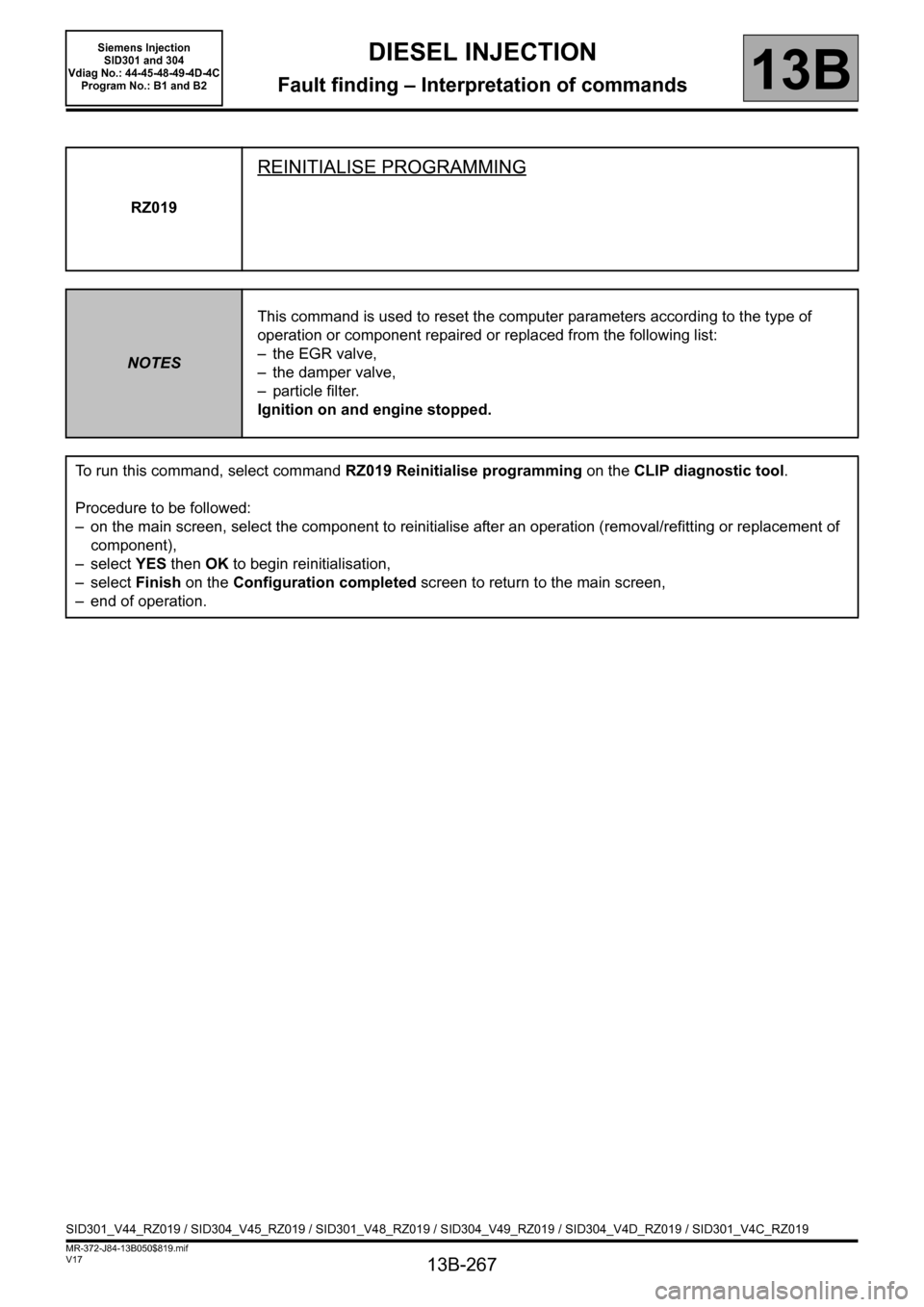
RZ019
REINITIALISE PROGRAMMING
NOTESThis command is used to reset the computer parameters according to the type of
operation or component repaired or replaced from the following list:
– the EGR valve,
– the damper valve,
– particle filter.
Ignition on and engine stopped.
To run this command, select command RZ019 Reinitialise programming on the CLIP diagnostic tool.
Procedure to be followed:
– on the main screen, select the component to reinitialise after an operation (removal/refitting or replacement of
component),
–select YES then OK to begin reinitialisation,
–select Finish on the Configuration completed screen to return to the main screen,
– end of operation.
SID301_V44_RZ019 / SID304_V45_RZ019 / SID301_V48_RZ019 / SID304_V49_RZ019 / SID304_V4D_RZ019 / SID301_V4C_RZ019