ESP RENAULT SCENIC 2011 J95 / 3.G Engine And Peripherals Owner's Manual
[x] Cancel search | Manufacturer: RENAULT, Model Year: 2011, Model line: SCENIC, Model: RENAULT SCENIC 2011 J95 / 3.GPages: 198, PDF Size: 0.85 MB
Page 142 of 198

13B-142
AFTER REPAIRCarry out a road test followed by another check with the diagnostic tool.
V4 MR-372-J84-13B000$090.mif
DIESEL INJECTION
Fault finding – Interpretation of statuses13B
DDCR INJECTION
Vdiag No.: 44, 48
ET704
ET705
CONTINUED
ACTIVE
OR
INACTIVE
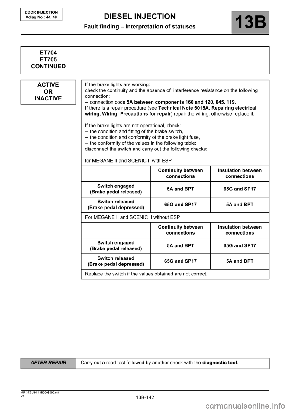
If the brake lights are working:
check the continuity and the absence of interference resistance on the following
connection:
– connection code 5A between components 160 and 120, 645, 119.
If there is a repair procedure (see Technical Note 6015A, Repairing electrical
wiring, Wiring: Precautions for repair) repair the wiring, otherwise replace it.
If the brake lights are not operational, check:
– the condition and fitting of the brake switch,
– the condition and conformity of the brake light fuse,
– the conformity of the values in the following table:
disconnect the switch and carry out the following checks:
for MEGANE II and SCENIC II with ESP
Continuity between
connectionsInsulation between
connections
Switch engaged
(Brake pedal released)5A and BPT 65G and SP17
Switch released
(Brake pedal depressed)65G and SP17 5A and BPT
For MEGANE II and SCENIC II without ESP
Continuity between
connectionsInsulation between
connections
Switch engaged
(Brake pedal released)5A and BPT 65G and SP17
Switch released
(Brake pedal depressed)65G and SP17 5A and BPT
Replace the switch if the values obtained are not correct.
Page 155 of 198

13B-155V4 MR-372-J84-13B000$120.mif
DIESEL INJECTION
Fault finding – Tests13B
DDCR INJECTION
Vdiag No.: 44, 48
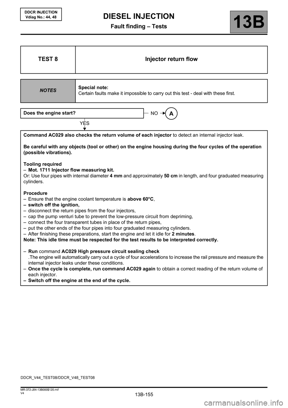
TEST 8 Injector return flow
NOTESSpecial note:
Certain faults make it impossible to carry out this test - deal with these first.
Does the engine start?
Command AC029 also checks the return volume of each injector to detect an internal injector leak.
Be careful with any objects (tool or other) on the engine housing during the four cycles of the operation
(possible vibrations).
Tooling required
–Mot. 1711 Injector flow measuring kit.
Or: Use four pipes with internal diameter 4mm and approximately 50 cm in length, and four graduated measuring
cylinders.
Procedure
– Ensure that the engine coolant temperature is above 60°C,
– switch off the ignition,
– disconnect the return pipes from the four injectors,
– cap the pump venturi tube to prevent the low-pressure circuit from depriming,
– connect the four transparent tubes in place of the return pipes,
– put the other ends of the four pipes into four graduated measuring cylinders.
– After finishing these preparations, start the engine and let it idle for 2 minutes.
Note: This idle time must be respected for the test results to be interpreted correctly.
–Run command AC029 High pressure circuit sealing check
.The engine will automatically carry out a cycle of four accelerations to increase the rail pressure and measure the
internal injector leaks under these conditions.
–Once the cycle is complete, run command AC029 again to obtain a correct reading of the return volume of
each injector.
– Switch off the engine at the end of the cycle.
NOA
YES
DDCR_V44_TEST08/DDCR_V48_TEST08
Page 195 of 198

13B-195
AFTER REPAIRCarry out a road test, then check with the diagnostic tool.
V4 MR-372-J84-13B000$140.mif
DIESEL INJECTION
Fault finding – Fault finding charts13B
InjectionDDCR
Vdiag No.: 44, 48
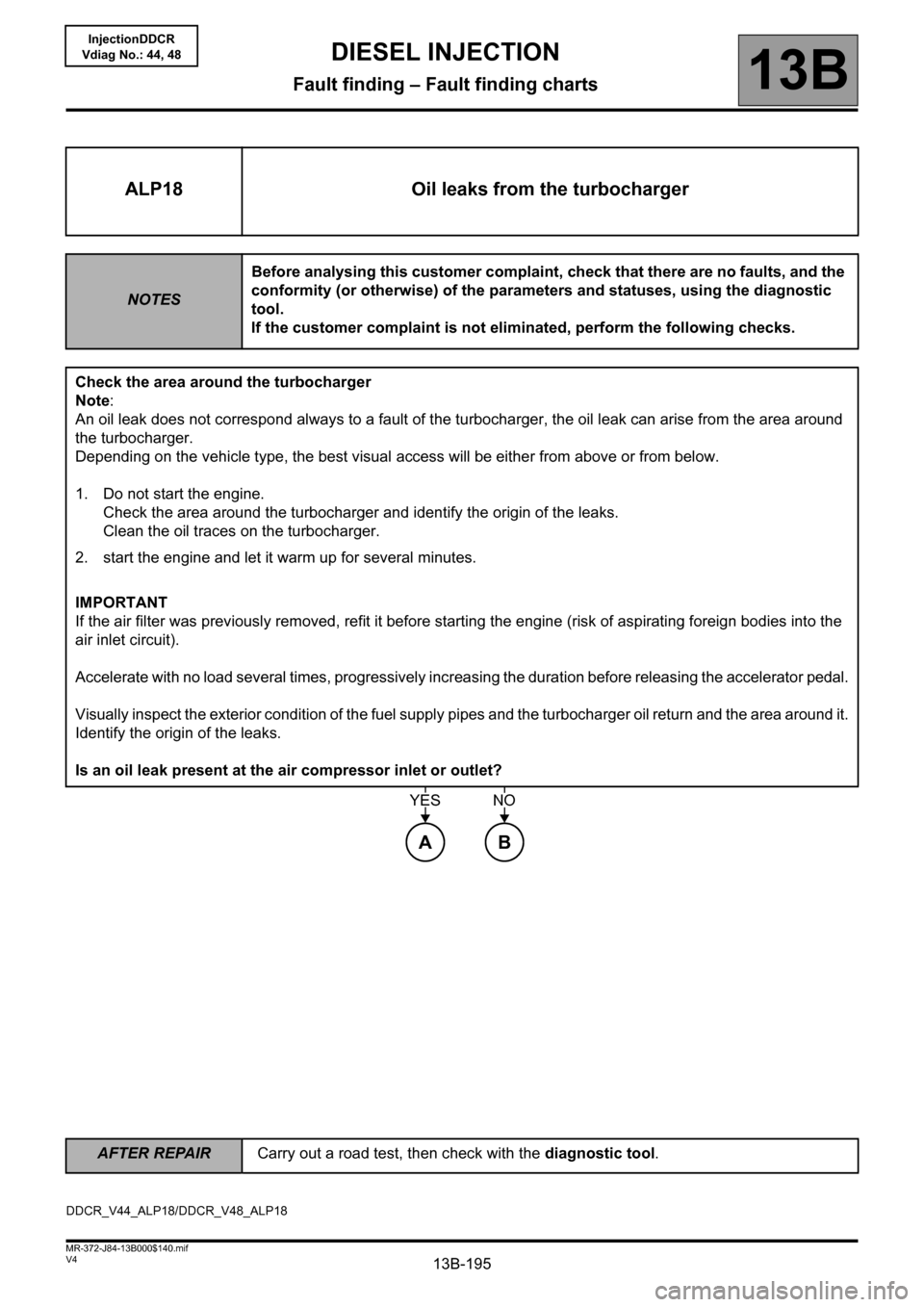
ALP18 Oil leaks from the turbocharger
NOTESBefore analysing this customer complaint, check that there are no faults, and the
conformity (or otherwise) of the parameters and statuses, using the diagnostic
tool.
If the customer complaint is not eliminated, perform the following checks.
Check the area around the turbocharger
Note:
An oil leak does not correspond always to a fault of the turbocharger, the oil leak can arise from the area around
the turbocharger.
Depending on the vehicle type, the best visual access will be either from above or from below.
1. Do not start the engine.
Check the area around the turbocharger and identify the origin of the leaks.
Clean the oil traces on the turbocharger.
2. start the engine and let it warm up for several minutes.
IMPORTANT
If the air filter was previously removed, refit it before starting the engine (risk of aspirating foreign bodies into the
air inlet circuit).
Accelerate with no load several times, progressively increasing the duration before releasing the accelerator pedal.
Visually inspect the exterior condition of the fuel supply pipes and the turbocharger oil return and the area around it.
Identify the origin of the leaks.
Is an oil leak present at the air compressor inlet or outlet?
AB
YESNO
DDCR_V44_ALP18/DDCR_V48_ALP18