Starter engine RENAULT SCENIC 2011 J95 / 3.G Engine And Peripherals Workshop Manual
[x] Cancel search | Manufacturer: RENAULT, Model Year: 2011, Model line: SCENIC, Model: RENAULT SCENIC 2011 J95 / 3.GPages: 198, PDF Size: 0.85 MB
Page 18 of 198

13B-18V4 MR-372-J84-13B000$030.mif
13B
DDCR INJECTION
Vdiag No.: 44, 48
COMPUTER REPLACEMENT, PROGRAMMING AND REPROGRAMMING OPERATIONS
Before reprogramming or removing the computer in After-Sales operations, save the following data to the
diagnostic tool:
– The C2I parameters (individual injector correction) and the engine adaptives using command SC003 Save
computer data.
The system can be reprogrammed with the diagnostic socket using the RENAULT CLIP diagnostic tool
(Consult Technical Note 3585A, Computer programming and reprogramming procedure, and follow the
instructions given by the diagnostic tool).
Any time the computer has been reprogrammed
– Use the diagnostic tool command SC001 Enter saved data to restore the C2I and the engine adaptives.
– Use command AC028 Static test to reinitialise the computer (fan assembly, etc.).
– When changing the pump, refer to the high pressure pump replacement procedure (consult Technical Note 5011A,
Repriming Delphi high pressure pumps on K9K engines).
– Switch the ignition off and then on again.
–Activate the starter without releasing the key until the engine starts (the engine start time can be up to 20
seconds).
– Stop the engine (to initialise the computer) and wait 30 seconds.
– Switch the ignition on again and use the diagnostic tool to carry out the following steps:
– Run command VP010 Enter VIN.
– After injection system programming, stored faults may appear on other computers. Clear the memory of these
computers. IMPORTANT:
Before reprogramming the injection computer, move the main Cruise control/Speed limiter switch to the rest
position. The information about the cruise control or the speed limiter displayed on the instrument panel
disappears.
Otherwise, if the main switch remains in the cruise control or speed limiter position during and after reprogramming,
the Cruise control/Speed limiter function will not be operational.
The procedure for resetting the function is as follows:
Vehicle ignition on.
Main switch in rest position (the computer then detects the rest position).
Switch in Cruise control position to activate the Cruise control function.
Switch in Speed limiter position to activate the Speed limiter function.
IMPORTANT
– Switch on the diagnostic tool (mains or cigarette lighter supply).
– Connect a battery charger.
– Switch off all electrical consumers (lights, interior lights, air conditioning, radio/CD, etc.).
– Wait for the engine to cool (engine coolant temperature below 60°C and air temperature below 50°C).
DIESEL INJECTION
Fault finding – Replacement of components
Page 27 of 198
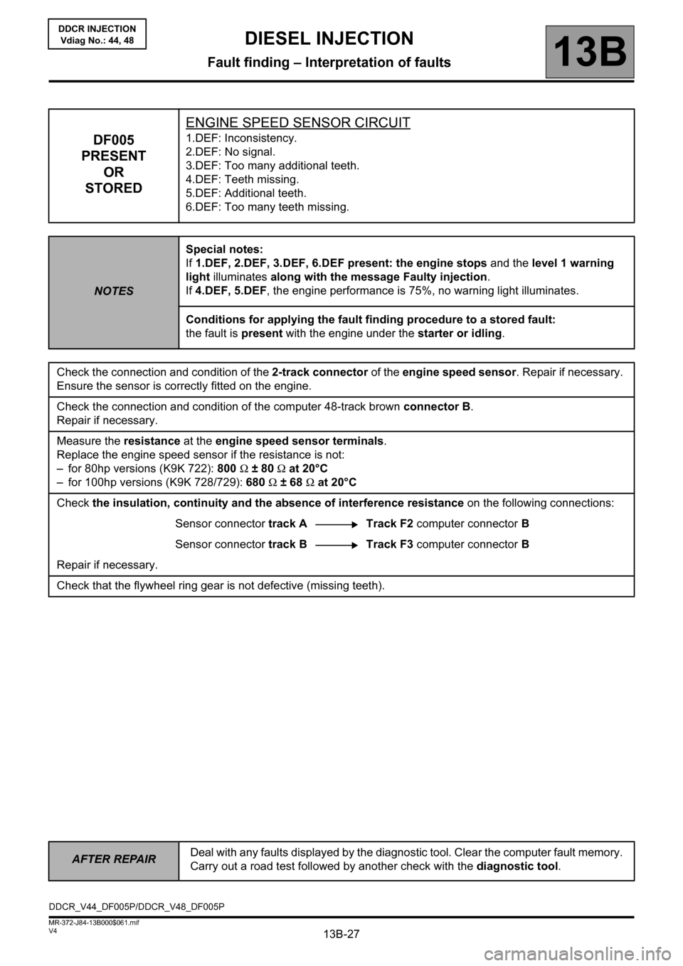
13B-27
AFTER REPAIRDeal with any faults displayed by the diagnostic tool. Clear the computer fault memory.
Carry out a road test followed by another check with the diagnostic tool.
V4 MR-372-J84-13B000$061.mif
DIESEL INJECTION
Fault finding – Interpretation of faults13B
DDCR INJECTION
Vdiag No.: 44, 48
DF005
PRESENT
OR
STOREDENGINE SPEED SENSOR CIRCUIT1.DEF: Inconsistency.
2.DEF: No signal.
3.DEF: Too many additional teeth.
4.DEF: Teeth missing.
5.DEF: Additional teeth.
6.DEF: Too many teeth missing.
NOTESSpecial notes:
If 1.DEF, 2.DEF, 3.DEF, 6.DEF present: the engine stops and the level 1 warning
light illuminates along with the message Faulty injection.
If 4.DEF, 5.DEF, the engine performance is 75%, no warning light illuminates.
Conditions for applying the fault finding procedure to a stored fault:
the fault is present with the engine under the starter or idling.
Check the connection and condition of the 2-track connector of the engine speed sensor. Repair if necessary.
Ensure the sensor is correctly fitted on the engine.
Check the connection and condition of the computer 48-track brown connector B.
Repair if necessary.
Measure the resistance at the engine speed sensor terminals.
Replace the engine speed sensor if the resistance is not:
– for 80hp versions (K9K 722): 800 Ω ± 80 Ω at 20°C
– for 100hp versions (K9K 728/729): 680 Ω ± 68 Ω at 20°C
Check the insulation, continuity and the absence of interference resistance on the following connections:
Sensor connector track A Track F2 computer connector B
Sensor connector track BTrack F3 computer connector B
Repair if necessary.
Check that the flywheel ring gear is not defective (missing teeth).
DDCR_V44_DF005P/DDCR_V48_DF005P
Page 73 of 198
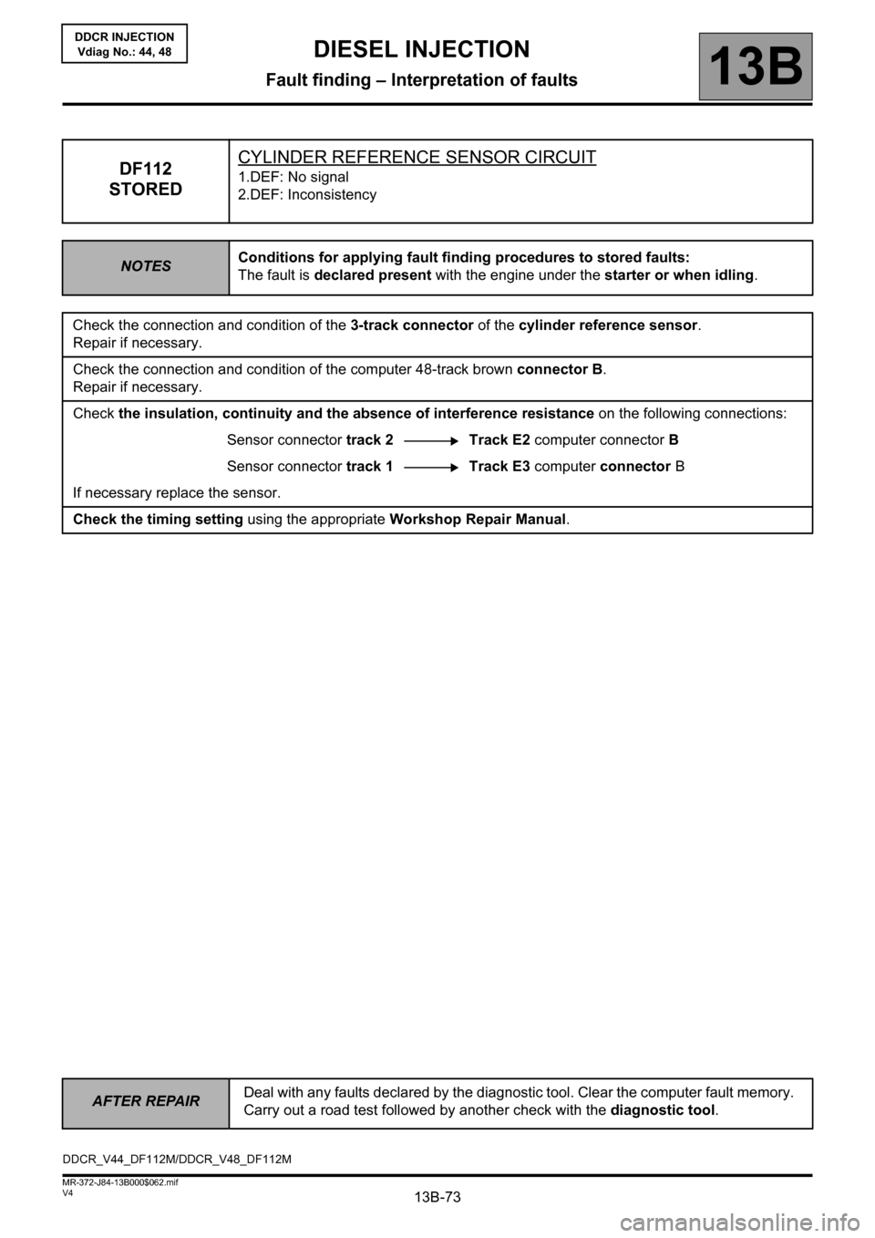
13B-73
AFTER REPAIRDeal with any faults declared by the diagnostic tool. Clear the computer fault memory.
Carry out a road test followed by another check with the diagnostic tool.
V4 MR-372-J84-13B000$062.mif
DIESEL INJECTION
Fault finding – Interpretation of faults13B
DDCR INJECTION
Vdiag No.: 44, 48
DF112
STOREDCYLINDER REFERENCE SENSOR CIRCUIT1.DEF: No signal
2.DEF: Inconsistency
NOTESConditions for applying fault finding procedures to stored faults:
The fault is declared present with the engine under the starter or when idling.
Check the connection and condition of the 3-track connector of the cylinder reference sensor.
Repair if necessary.
Check the connection and condition of the computer 48-track brown connector B.
Repair if necessary.
Check the insulation, continuity and the absence of interference resistance on the following connections:
Sensor connector track 2 Track E2 computer connector B
Sensor connector track 1Track E3 computer connector B
If necessary replace the sensor.
Check the timing setting using the appropriate Workshop Repair Manual.
DDCR_V44_DF112M/DDCR_V48_DF112M
Page 85 of 198

13B-85V4 MR-372-J84-13B000$070.mif
DIESEL INJECTION
Fault finding – Conformity check13B
DDCR INJECTION
Vdiag No.: 44, 48
MAIN COMPUTER STATUSES AND PARAMETERS: (continued 2)
NOTESOnly check conformity after a full check with the diagnostic tool.
The values shown in this conformity check are given as examples.
Application conditions: Engine off, ignition on.
FunctionParameter or Status
Check or actionDisplay and notes Fault finding
EngineET038: Engine.
UNDER + AFTER
IGNITION FEEDIndicates the current status of
the engine.
- UNDER + AFTER IGNITION
FEED
- UNDER STARTER
- RUNNING
- SUPPLY MAINTAINED: Supply
maintained during the power
latch phase.
- STALLED: When the engine
has stalled.
- PROTECTED: When a level 2
fault has appeared or when
the engine speed is locked at
a certain value.NONE
Engine
immobiliserET003: Engine
immobiliser.
INACTIVEIndicates the status of the
immobiliser system.
- INACTIVE: The injection
computer has recognised the
immobiliser code transmitted
by the UCH.
- ACTIVE: The injection
computer does not recognise
the immobiliser code
transmitted by the UCH.If ACTIVE, apply the
associated Help given in
the tool.
Code
programmedET006: Code
programmed
YESIndicates whether the
immobiliser code has been
programmed into the computer.
- YES: Code is programmed.
- NO: Code was not
programmed into the injection
computer.If NO, contact the Techline.
Page 87 of 198
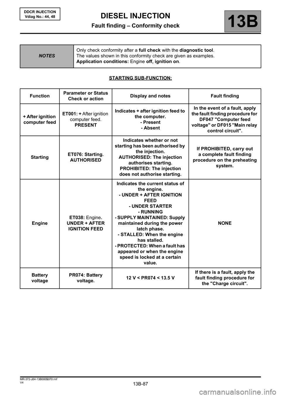
13B-87V4 MR-372-J84-13B000$070.mif
DIESEL INJECTION
Fault finding – Conformity check13B
DDCR INJECTION
Vdiag No.: 44, 48
STARTING SUB-FUNCTION:
NOTESOnly check conformity after a full check with the diagnostic tool.
The values shown in this conformity check are given as examples.
Application conditions: Engine off, ignition on.
FunctionParameter or Status
Check or actionDisplay and notes Fault finding
+ After ignition
computer feedET001: + After ignition
computer feed.
PRESENTIndicates + after ignition feed to
the computer.
- Present
- AbsentIn the event of a fault, apply
the fault finding procedure for
DF047 "Computer feed
voltage" or DF015 "Main relay
control circuit".
StartingET076: Starting.
AUTHORISEDIndicates whether or not
starting has been authorised by
the injection.
AUTHORISED: The injection
authorises starting.
PROHIBITED: The injection
does not authorise starting.If PROHIBITED, carry out
a complete fault finding
procedure on the preheating
system.
EngineET038: Engine.
UNDER + AFTER
IGNITION FEEDIndicates the current status of
the engine.
- UNDER + AFTER IGNITION
FEED
- UNDER STARTER
- RUNNING
- SUPPLY MAINTAINED: Supply
maintained during the power
latch phase.
- STALLED: When the engine
has stalled.
- PROTECTED: When a fault has
appeared or when the engine
speed is locked at a certain
value.NONE
Battery
voltagePR074: Battery
voltage.12 V < PR074 < 13.5 VIf there is a fault, apply the
fault finding procedure for
the "Charge circuit".
Page 105 of 198
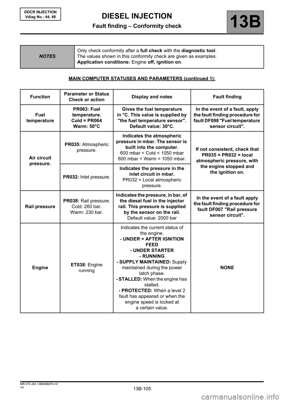
13B-105V4 MR-372-J84-13B000$070.mif
DIESEL INJECTION
Fault finding – Conformity check13B
DDCR INJECTION
Vdiag No.: 44, 48
MAIN COMPUTER STATUSES AND PARAMETERS (continued 1):
NOTESOnly check conformity after a full check with the diagnostic tool.
The values shown in this conformity check are given as examples.
Application conditions: Engine off, ignition on.
FunctionParameter or Status
Check or actionDisplay and notes Fault finding
Fuel
temperaturePR063: Fuel
temperature.
Cold = PR064
Warm: 50°CGives the fuel temperature
in °C. This value is supplied by
"the fuel temperature sensor".
Default value: 30°C.In the event of a fault, apply
the fault finding procedure for
fault DF098 "Fuel temperature
sensor circuit".
Air circuit
pressure.PR035: Atmospheric
pressure.Indicates the atmospheric
pressure in mbar. The sensor is
built into the computer.
600 mbar < Cold < 1050 mbar
600 mbar < Warm < 1050 mbar.If not consistent, check that
PR035 = PR032 = local
atmospheric pressure, with
the engine stopped and
the ignition on.
PR032: Inlet pressure.Indicates the pressure in the
inlet circuit in mbar.
PR032 = Local atmospheric
pressure.
Rail pressurePR038: Rail pressure.
Cold: 260 bar.
Warm: 230 bar.Indicates the pressure, in bar, of
the diesel fuel in the injector
rail. This pressure is supplied
by the sensor on the rail.
Default value: 2000 barIn the event of a fault apply
the fault finding procedure for
fault DF007 "Rail pressure
sensor circuit".
EngineET038: Engine
runningIndicates the current status of
the engine.
- UNDER + AFTER IGNITION
FEED
- UNDER STARTER
- RUNNING
- SUPPLY MAINTAINED: Supply
maintained during the power
latch phase.
- STALLED: When the engine has
stalled.
- PROTECTED: When a level 2
fault has appeared or when the
engine speed is locked at
a certain value.NONE
Page 107 of 198
13B-107V4 MR-372-J84-13B000$070.mif
DIESEL INJECTION
Fault finding – Conformity check13B
DDCR INJECTION
Vdiag No.: 44, 48
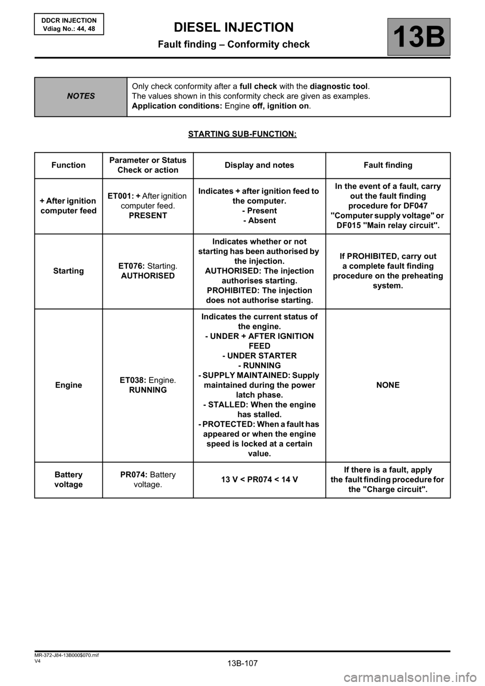
STARTING SUB-FUNCTION:
NOTESOnly check conformity after a full check with the diagnostic tool.
The values shown in this conformity check are given as examples.
Application conditions: Engine off, ignition on.
FunctionParameter or Status
Check or actionDisplay and notes Fault finding
+ After ignition
computer feedET001: + After ignition
computer feed.
PRESENTIndicates + after ignition feed to
the computer.
- Present
- AbsentIn the event of a fault, carry
out the fault finding
procedure for DF047
"Computer supply voltage" or
DF015 "Main relay circuit".
StartingET076: Starting.
AUTHORISEDIndicates whether or not
starting has been authorised by
the injection.
AUTHORISED: The injection
authorises starting.
PROHIBITED: The injection
does not authorise starting.If PROHIBITED, carry out
a complete fault finding
procedure on the preheating
system.
EngineET038: Engine.
RUNNINGIndicates the current status of
the engine.
- UNDER + AFTER IGNITION
FEED
- UNDER STARTER
- RUNNING
- SUPPLY MAINTAINED: Supply
maintained during the power
latch phase.
- STALLED: When the engine
has stalled.
- PROTECTED: When a fault has
appeared or when the engine
speed is locked at a certain
value.NONE
Battery
voltagePR074: Battery
voltage.13 V < PR074 < 14 VIf there is a fault, apply
the fault finding procedure for
the "Charge circuit".
Page 157 of 198
13B-157V4 MR-372-J84-13B000$120.mif
DIESEL INJECTION
Fault finding – Tests13B
DDCR INJECTION
Vdiag No.: 44, 48
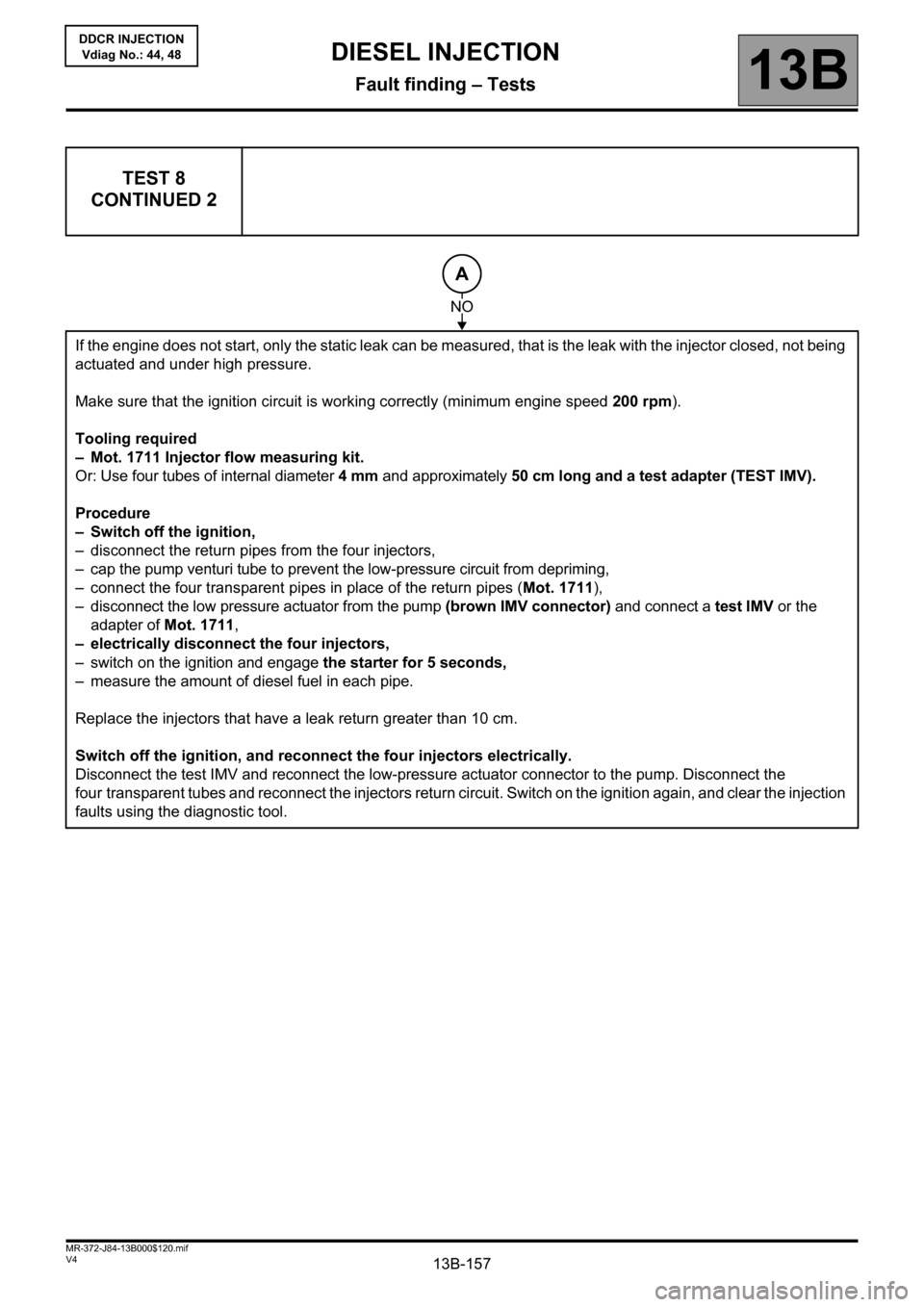
TEST 8
CONTINUED 2
If the engine does not start, only the static leak can be measured, that is the leak with the injector closed, not being
actuated and under high pressure.
Make sure that the ignition circuit is working correctly (minimum engine speed 200 rpm).
Tooling required
– Mot. 1711 Injector flow measuring kit.
Or: Use four tubes of internal diameter 4 mm and approximately 50 cm long and a test adapter (TEST IMV).
Procedure
– Switch off the ignition,
– disconnect the return pipes from the four injectors,
– cap the pump venturi tube to prevent the low-pressure circuit from depriming,
– connect the four transparent pipes in place of the return pipes (Mot. 1711),
– disconnect the low pressure actuator from the pump (brown IMV connector) and connect a test IMV or the
adapter of Mot. 1711,
– electrically disconnect the four injectors,
– switch on the ignition and engage the starter for 5 seconds,
– measure the amount of diesel fuel in each pipe.
Replace the injectors that have a leak return greater than 10 cm.
Switch off the ignition, and reconnect the four injectors electrically.
Disconnect the test IMV and reconnect the low-pressure actuator connector to the pump. Disconnect the
four transparent tubes and reconnect the injectors return circuit. Switch on the ignition again, and clear the injection
faults using the diagnostic tool.
A
NO
Page 168 of 198
13B-168
AFTER REPAIRCarry out a road test, then check with the diagnostic tool.
V4 MR-372-J84-13B000$140.mif
DIESEL INJECTION
Fault finding – Fault finding charts13B
InjectionDDCR
Vdiag No.: 44, 48
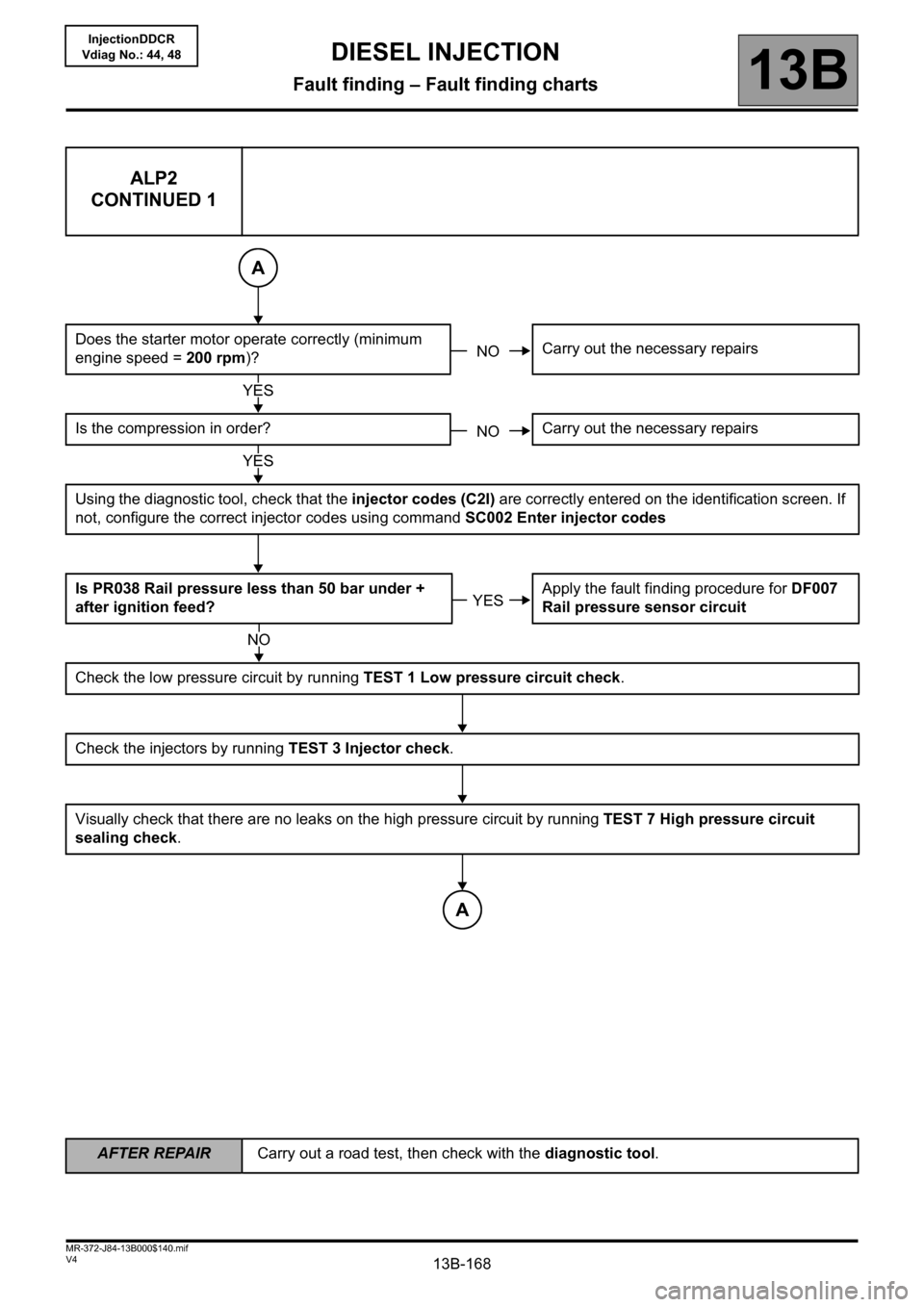
ALP2
CONTINUED 1
Does the starter motor operate correctly (minimum
engine speed = 200 rpm)?Carry out the necessary repairs
Is the compression in order? Carry out the necessary repairs
Using the diagnostic tool, check that the injector codes (C2I) are correctly entered on the identification screen. If
not, configure the correct injector codes using command SC002 Enter injector codes
Is PR038 Rail pressure less than 50 bar under +
after ignition feed?Apply the fault finding procedure for DF007
Rail pressure sensor circuit
Check the low pressure circuit by running TEST 1 Low pressure circuit check.
Check the injectors by running TEST 3 Injector check.
Visually check that there are no leaks on the high pressure circuit by running TEST 7 High pressure circuit
sealing check.
A
NO
YES
NO
YES
YES
NO
A