fuse RENAULT SCENIC 2011 J95 / 3.G Engine And Peripherals Workshop Manual
[x] Cancel search | Manufacturer: RENAULT, Model Year: 2011, Model line: SCENIC, Model: RENAULT SCENIC 2011 J95 / 3.GPages: 198, PDF Size: 0.85 MB
Page 5 of 198
13B-5V4 MR-372-J84-13B000$010.mif
DIESEL INJECTION
Fault finding – Introduction13B
DDCR INJECTION
Vdiag No.: 44, 48
4. FAULT FINDING PROCEDURE (continued)
Wiring check
Fault finding problems
Disconnecting the connectors and/or manipulating the wiring may temporarily clear the cause of a fault.
The electrical measurements of the voltage, resistance, and insulation are generally correct, especially if the fault is
not present when the measurements are being taken (stored fault).
Visual inspection
Look for damage under the bonnet and in the passenger compartment.
Carefully check the fuses, insulators and wiring harness routing.
Look for signs of oxidation.
Physical inspection
When handling the wiring, use the diagnostic tool to detect any change in the status of the fault from stored to
present.
Make sure that the connectors are firmly locked.
Apply light pressure to the connectors.
Twist the wiring harness.
If there is a change in status, try to locate the source of the fault.
Inspection of each component
Disconnect the connectors and check the appearance of the clips and tabs as well as their crimping (no crimping on
the insulation). Check that the clips and the tabs are correctly locked in the sockets.
Check that no clips or tabs have been dislodged during connection.
Check the clip contact pressure using an appropriate model of tab.
Resistance check
Check the continuity of entire lines, then section by section.
Look for a short circuit to earth, to + 12 V or with another wire.
If a fault is detected, repair or replace the wiring harness.
5. FAULT FINDING LOG
IMPORTANTIMPORTANT
Any fault on a complex system requires thorough fault finding with the appropriate tools.
The FAULT FINDING LOG, which should be completed during the procedure, enables you to
keep track of the procedure which is carried out. It is an essential document when consulting
the manufacturer.
IT IS THEREFORE COMPULSORY TO COMPLETE A FAULT FINDING LOG EVERY TIME A FAULT FINDING
PROCEDURE IS PERFORMED
Page 35 of 198
13B-35
AFTER REPAIRDeal with any faults displayed by the diagnostic tool. Clear the computer fault memory.
Carry out a road test followed by another check with the diagnostic tool.
V4 MR-372-J84-13B000$061.mif
DIESEL INJECTION
Fault finding – Interpretation of faults13B
DDCR INJECTION
Vdiag No.: 44, 48
DF015
PRESENTMAIN RELAY control CIRCUIT1.DEF: Permanent low level.
2.DEF: Permanent high level.
NOTESSpecial notes: The main relay is built into the UPC.
Check the main relay supply fuse in the engine compartment: (30 A fuse) on the UPC.
Replace the fuse if necessary.
Check the condition and connection of the brown 12-track PEM D and black 4-track PPM1 connectors on the
UPC.
Repair if necessary.
Check the connection and condition of the computer's 32-track grey connector C.
Repair if necessary.
Check the insulation, continuity and the absence of interference resistance on the following connections:
Computer connector C track F1Track 2 brown 12-track connector PEM D of the
UPC.
Computer connector C track G1 Vehicle earth.
Computer connector C track H2Track 1 black 4-track connector PPM1 of the
UPC.
Computer connector C track G2Track 1 black 4-track connector PPM1 of the
UPC.
Repair if necessary
DDCR_V44_DF015P/DDCR_V48_DF015P
Page 82 of 198
13B-82
AFTER REPAIRDeal with any faults declared by the diagnostic tool. Clear the computer fault memory.
Carry out a road test followed by another check with the diagnostic tool.
V4 MR-372-J84-13B000$062.mif
DIESEL INJECTION
Fault finding – Interpretation of faults13B
DDCR INJECTION
Vdiag No.: 44, 48
DF1070
PRESENT
OR
STOREDCOLD LOOP
1.DEF: Jammed component
NOTESConditions for applying fault finding procedures to stored faults:
The fault is declared present with the engine running and with a climate control request.
Priorities when dealing with a number of faults:
– DF049 Refrigerant sensor circuit if it is present or stored.
When the fault is present or stored, the heating and air conditioning system is inhibited. There is no longer any air
conditioning.
Check fuse F22 (10 A) of the UPC, component code 1337.
Check the connector of the air conditioning compressor, component code 171.
If the connector is faulty and there is a repair method (see Technical Note 6015A, Repairing electrical wiring,
Wiring: Precautions for repair), repair the connector, otherwise replace the wiring.
Check the wiring of the air conditioning compressor.
If the wiring is faulty and there is a repair procedure (see Technical Note 6015A, Repairing electrical wiring,
Wiring: Precautions for repair), repair the wiring, otherwise replace the wiring.
Manually check if the compressor is jammed (turn the clutch plate manually to check that there is no point of
resistance). In the event of jamming, replace the air conditioning compressor (see MR 364 (Mégane II), MR 370
(Scénic II), Mechanical, 62A, Air conditioning, Compressor: Removal - Refitting).
Top up the refrigerant, check for any leaks, and repair if necessary (see MR 364 (Mégane II), MR 370 (Scénic II),
Mechanical, 62A, Air conditioning, Refrigerant circuit: Draining - Filling).
DDCR__V44_DF1070 / DDCR_V48_DF1070
Page 142 of 198

13B-142
AFTER REPAIRCarry out a road test followed by another check with the diagnostic tool.
V4 MR-372-J84-13B000$090.mif
DIESEL INJECTION
Fault finding – Interpretation of statuses13B
DDCR INJECTION
Vdiag No.: 44, 48
ET704
ET705
CONTINUED
ACTIVE
OR
INACTIVE
If the brake lights are working:
check the continuity and the absence of interference resistance on the following
connection:
– connection code 5A between components 160 and 120, 645, 119.
If there is a repair procedure (see Technical Note 6015A, Repairing electrical
wiring, Wiring: Precautions for repair) repair the wiring, otherwise replace it.
If the brake lights are not operational, check:
– the condition and fitting of the brake switch,
– the condition and conformity of the brake light fuse,
– the conformity of the values in the following table:
disconnect the switch and carry out the following checks:
for MEGANE II and SCENIC II with ESP
Continuity between
connectionsInsulation between
connections
Switch engaged
(Brake pedal released)5A and BPT 65G and SP17
Switch released
(Brake pedal depressed)65G and SP17 5A and BPT
For MEGANE II and SCENIC II without ESP
Continuity between
connectionsInsulation between
connections
Switch engaged
(Brake pedal released)5A and BPT 65G and SP17
Switch released
(Brake pedal depressed)65G and SP17 5A and BPT
Replace the switch if the values obtained are not correct.
Page 149 of 198
13B-149V4 MR-372-J84-13B000$120.mif
DIESEL INJECTION
Fault finding – Tests13B
DDCR INJECTION
Vdiag No.: 44, 48
TEST 2 Electrical circuit check
Check the battery charge and that the alternator is
operating correctly (see 87G, Engine compartment
connection unit for Mégane II or Scénic II).
Is the charging circuit in good order? Carry out the necessary repairs
Check the fuses.
Are the fuses correct? Carry out the necessary repairs
Check that the injection locking relay is operating
correctly.
Is the injection locking relay working properly? Carry out the necessary repairs
Check the engine earths.
Are the engine earths correct?Carry out the necessary repairs
The electrical circuit is in good order.
NO
YES
NO
YES
NO
YES
NO
YES
DDCR_V44_TEST02/DDCR_V48_TEST02
Page 166 of 198
13B-166
AFTER REPAIRCarry out a road test, then check with the diagnostic tool.
V4 MR-372-J84-13B000$140.mif
13B
InjectionDDCR
Vdiag No.: 44, 48
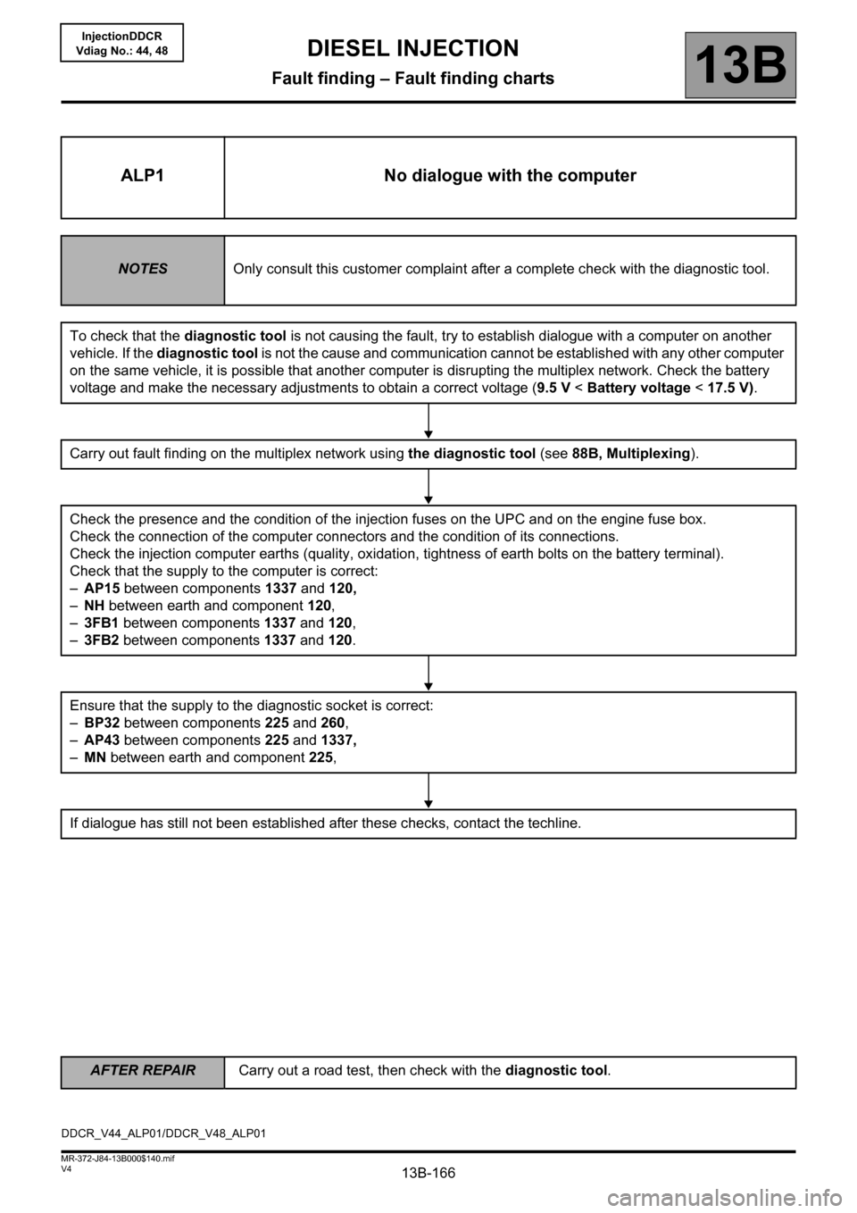
ALP1 No dialogue with the computer
NOTESOnly consult this customer complaint after a complete check with the diagnostic tool.
To check that the diagnostic tool is not causing the fault, try to establish dialogue with a computer on another
vehicle. If the diagnostic tool is not the cause and communication cannot be established with any other computer
on the same vehicle, it is possible that another computer is disrupting the multiplex network. Check the battery
voltage and make the necessary adjustments to obtain a correct voltage (9.5 V < Battery voltage < 17.5 V).
Carry out fault finding on the multiplex network using the diagnostic tool (see 88B, Multiplexing).
Check the presence and the condition of the injection fuses on the UPC and on the engine fuse box.
Check the connection of the computer connectors and the condition of its connections.
Check the injection computer earths (quality, oxidation, tightness of earth bolts on the battery terminal).
Check that the supply to the computer is correct:
–AP15 between components 1337 and 120,
–NH between earth and component 120,
–3FB1 between components 1337 and 120,
–3FB2 between components 1337 and 120.
Ensure that the supply to the diagnostic socket is correct:
–BP32 between components 225 and 260,
–AP43 between components 225 and 1337,
–MN between earth and component 225,
If dialogue has still not been established after these checks, contact the techline.
DDCR_V44_ALP01/DDCR_V48_ALP01
DIESEL INJECTION
Fault finding – Fault finding charts