engine RENAULT SCENIC 2012 J95 / 3.G Engine And Peripherals EDC16CP33 Workshop Manual
[x] Cancel search | Manufacturer: RENAULT, Model Year: 2012, Model line: SCENIC, Model: RENAULT SCENIC 2012 J95 / 3.GPages: 510, PDF Size: 2.98 MB
Page 131 of 510
13B-131
AFTER REPAIRDeal with any other faults. Clear the fault memory.
Switch off the ignition until the end of the power-latch phase, and carry out a road test
followed by a check with the diagnostic tool.
V12 MR-372-J84-13B300$072.mif
DIESEL INJECTION
Fault finding – Interpretation of faults13B
EDC16CP33
Program No.: C4
Vdiag No.: 04, 08, 18, 1C,
20, 24, 26, 28, 34, 38, 44,
4C, 54, 58, 5C, 60, 62, 74
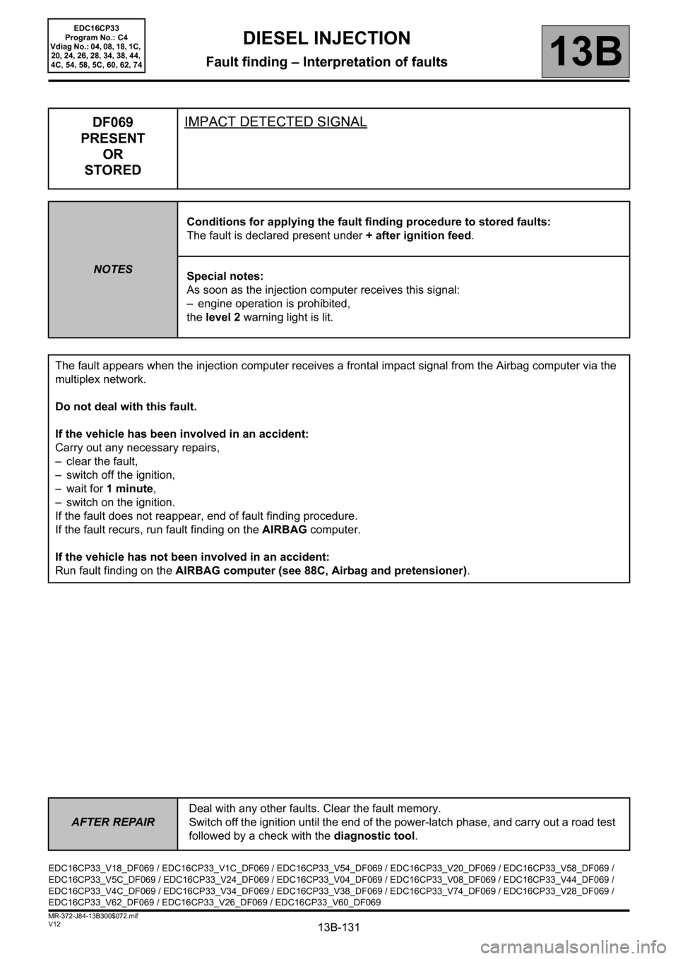
DF069
PRESENT
OR
STOREDIMPACT DETECTED SIGNAL
NOTESConditions for applying the fault finding procedure to stored faults:
The fault is declared present under + after ignition feed.
Special notes:
As soon as the injection computer receives this signal:
– engine operation is prohibited,
the level 2 warning light is lit.
The fault appears when the injection computer receives a frontal impact signal from the Airbag computer via the
multiplex network.
Do not deal with this fault.
If the vehicle has been involved in an accident:
Carry out any necessary repairs,
– clear the fault,
– switch off the ignition,
–wait for 1 minute,
– switch on the ignition.
If the fault does not reappear, end of fault finding procedure.
If the fault recurs, run fault finding on the AIRBAG computer.
If the vehicle has not been involved in an accident:
Run fault finding on the AIRBAG computer (see 88C, Airbag and pretensioner).
EDC16CP33_V18_DF069 / EDC16CP33_V1C_DF069 / EDC16CP33_V54_DF069 / EDC16CP33_V20_DF069 / EDC16CP33_V58_DF069 /
EDC16CP33_V5C_DF069 / EDC16CP33_V24_DF069 / EDC16CP33_V04_DF069 / EDC16CP33_V08_DF069 / EDC16CP33_V44_DF069 /
EDC16CP33_V4C_DF069 / EDC16CP33_V34_DF069 / EDC16CP33_V38_DF069 / EDC16CP33_V74_DF069 / EDC16CP33_V28_DF069 /
EDC16CP33_V62_DF069 / EDC16CP33_V26_DF069 / EDC16CP33_V60_DF069
Page 132 of 510
13B-132
AFTER REPAIRDeal with any other faults. Clear the fault memory.
Switch off the ignition until the end of the power-latch phase, and carry out a road test
followed by a check with the diagnostic tool.
V12 MR-372-J84-13B300$072.mif
DIESEL INJECTION
Fault finding – Interpretation of faults13B
EDC16CP33
Program No.: C4
Vdiag No.: 18, 1C, 20, 24,
26, 28, 54, 58, 5C, 60, 62
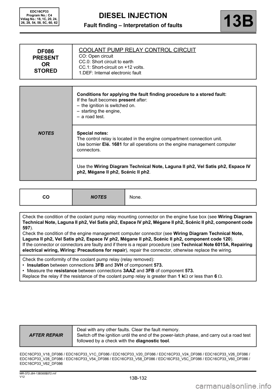
DF086
PRESENT
OR
STOREDCOOLANT PUMP RELAY CONTROL CIRCUITCO: Open circuit
CC.0: Short circuit to earth
CC.1: Short-circuit on +12 volts.
1.DEF: Internal electronic fault
NOTESConditions for applying the fault finding procedure to a stored fault:
If the fault becomes present after:
– the ignition is switched on.
– starting the engine,
– a road test.
Special notes:
The control relay is located in the engine compartment connection unit.
Use bornier Elé. 1681 for all operations on the engine management computer
connectors.
Use the Wiring Diagram Technical Note, Laguna II ph2, Vel Satis ph2, Espace IV
ph2, Mégane II ph2, Scénic II ph2.
CO
NOTESNone.
Check the condition of the coolant pump relay mounting connector on the engine fuse box (see Wiring Diagram
Technical Note, Laguna II ph2, Vel Satis ph2, Espace IV ph2, Mégane II ph2, Scénic II ph2, component code
597).
Check the condition of the engine management computer connector (see Wiring Diagram Technical Note,
Laguna II ph2, Vel Satis ph2, Espace IV ph2, Mégane II ph2, Scénic II ph2, component code 120).
If the connector or connectors are faulty and if there is a repair procedure (see Technical Note 6015A, Repairing
electrical wiring, Wiring: Precautions for repair), repair the connector, otherwise replace the wiring.
Check the conformity of the coolant pump relay (relay removed):
•Insulation between connections 3FB and 3VH of component 573.
• Measure the resistance between connections 3AAZ and 3FB of component 573.
Replace the relay if the resistance of the coolant pump relay is greater than 1 kΩ or less than 6 Ω.
EDC16CP33_V18_DF086 / EDC16CP33_V1C_DF086 / EDC16CP33_V20_DF086 / EDC16CP33_V24_DF086 / EDC16CP33_V26_DF086 /
EDC16CP33_V28_DF086 / EDC16CP33_V54_DF086 / EDC16CP33_V58_DF086 / EDC16CP33_V5C_DF086 / EDC16CP33_V60_DF086 /
EDC16CP33_V62_DF086
Page 133 of 510
13B-133
AFTER REPAIRDeal with any other faults. Clear the fault memory.
Switch off the ignition until the end of the power-latch phase, and carry out a road test
followed by a check with the diagnostic tool.
V12 MR-372-J84-13B300$072.mif
DIESEL INJECTION
Fault finding – Interpretation of faults13B
EDC16CP33
Program No.: C4
Vdiag No.: 18, 1C, 20, 24,
26, 28, 54, 58, 5C, 60, 62
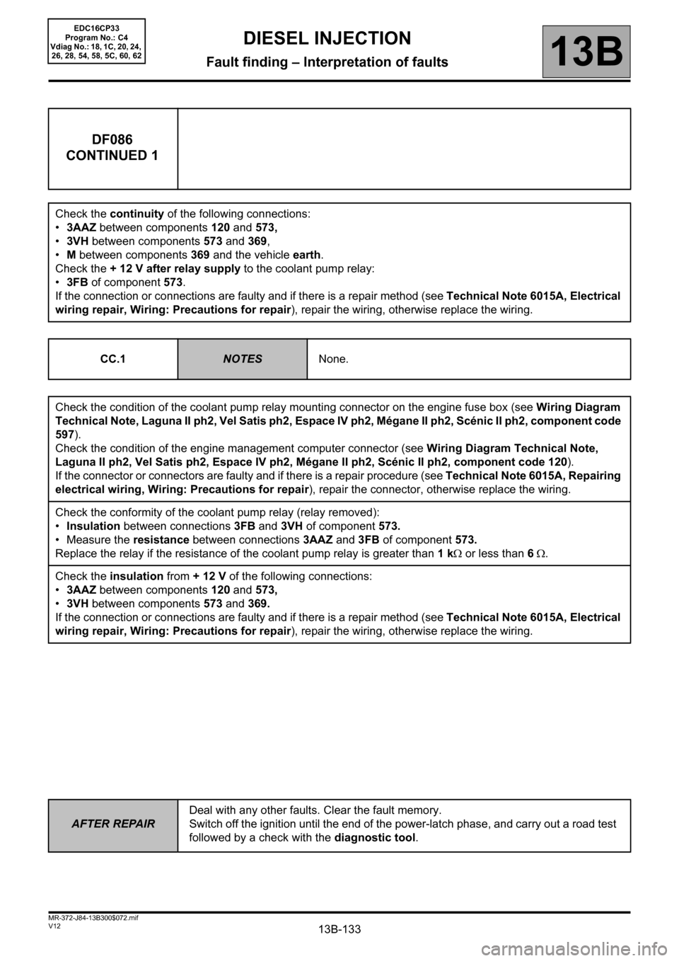
DF086
CONTINUED 1
Check the continuity of the following connections:
•3AAZ between components 120 and 573,
•3VH between components 573 and 369,
•M between components 369 and the vehicle earth.
Check the + 12 V after relay supply to the coolant pump relay:
•3FB of component 573.
If the connection or connections are faulty and if there is a repair method (see Technical Note 6015A, Electrical
wiring repair, Wiring: Precautions for repair), repair the wiring, otherwise replace the wiring.
CC.1
NOTESNone.
Check the condition of the coolant pump relay mounting connector on the engine fuse box (see Wiring Diagram
Technical Note, Laguna II ph2, Vel Satis ph2, Espace IV ph2, Mégane II ph2, Scénic II ph2, component code
597).
Check the condition of the engine management computer connector (see Wiring Diagram Technical Note,
Laguna II ph2, Vel Satis ph2, Espace IV ph2, Mégane II ph2, Scénic II ph2, component code 120).
If the connector or connectors are faulty and if there is a repair procedure (see Technical Note 6015A, Repairing
electrical wiring, Wiring: Precautions for repair), repair the connector, otherwise replace the wiring.
Check the conformity of the coolant pump relay (relay removed):
•Insulation between connections 3FB and 3VH of component 573.
• Measure the resistance between connections 3AAZ and 3FB of component 573.
Replace the relay if the resistance of the coolant pump relay is greater than 1 kΩ or less than 6 Ω.
Check the insulation from + 12 V of the following connections:
•3AAZ between components 120 and 573,
•3VH between components 573 and 369.
If the connection or connections are faulty and if there is a repair method (see Technical Note 6015A, Electrical
wiring repair, Wiring: Precautions for repair), repair the wiring, otherwise replace the wiring.
Page 134 of 510
13B-134
AFTER REPAIRDeal with any other faults. Clear the fault memory.
Switch off the ignition until the end of the power-latch phase, and carry out a road test
followed by a check with the diagnostic tool.
V12 MR-372-J84-13B300$072.mif
DIESEL INJECTION
Fault finding – Interpretation of faults13B
EDC16CP33
Program No.: C4
Vdiag No.: 18, 1C, 20, 24,
26, 28, 54, 58, 5C, 60, 62
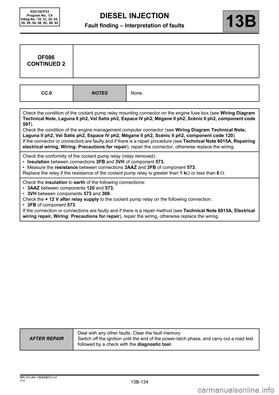
DF086
CONTINUED 2
CC.0NOTESNone.
Check the condition of the coolant pump relay mounting connector on the engine fuse box (see Wiring Diagram
Technical Note, Laguna II ph2, Vel Satis ph2, Espace IV ph2, Mégane II ph2, Scénic II ph2, component code
597).
Check the condition of the engine management computer connector (see Wiring Diagram Technical Note,
Laguna II ph2, Vel Satis ph2, Espace IV ph2, Mégane II ph2, Scénic II ph2, component code 120).
If the connector or connectors are faulty and if there is a repair procedure (see Technical Note 6015A, Repairing
electrical wiring, Wiring: Precautions for repair), repair the connector, otherwise replace the wiring.
Check the conformity of the coolant pump relay (relay removed):
•Insulation between connections 3FB and 3VH of component 573.
• Measure the resistance between connections 3AAZ and 3FB of component 573.
Replace the relay if the resistance of the coolant pump relay is greater than 1 kΩ or less than 6 Ω.
Check the insulation to earth of the following connections:
•3AAZ between components 120 and 573,
•3VH between components 573 and 369.
Check the + 12 V after relay supply to the coolant pump relay on the following connection:
•3FB of component 573.
If the connection or connections are faulty and if there is a repair method (see Technical Note 6015A, Electrical
wiring repair, Wiring: Precautions for repair), repair the wiring, otherwise replace the wiring.
Page 135 of 510
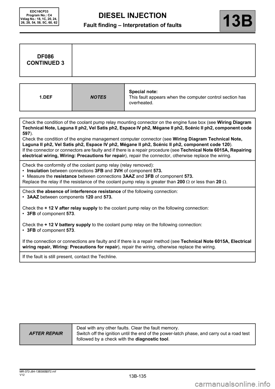
13B-135
AFTER REPAIRDeal with any other faults. Clear the fault memory.
Switch off the ignition until the end of the power-latch phase, and carry out a road test
followed by a check with the diagnostic tool.
V12 MR-372-J84-13B300$072.mif
DIESEL INJECTION
Fault finding – Interpretation of faults13B
EDC16CP33
Program No.: C4
Vdiag No.: 18, 1C, 20, 24,
26, 28, 54, 58, 5C, 60, 62
DF086
CONTINUED 3
1.DEFNOTESSpecial note:
This fault appears when the computer control section has
overheated.
Check the condition of the coolant pump relay mounting connector on the engine fuse box (see Wiring Diagram
Technical Note, Laguna II ph2, Vel Satis ph2, Espace IV ph2, Mégane II ph2, Scénic II ph2, component code
597).
Check the condition of the engine management computer connector (see Wiring Diagram Technical Note,
Laguna II ph2, Vel Satis ph2, Espace IV ph2, Mégane II ph2, Scénic II ph2, component code 120).
If the connector or connectors are faulty and if there is a repair procedure (see Technical Note 6015A, Repairing
electrical wiring, Wiring: Precautions for repair), repair the connector, otherwise replace the wiring.
Check the conformity of the coolant pump relay (relay removed):
•Insulation between connections 3FB and 3VH of component 573.
• Measure the resistance between connections 3AAZ and 3FB of component 573.
Replace the relay if the resistance of the coolant pump relay is greater than 200 Ω or less than 20 Ω.
Check the absence of interference resistance of the following connection:
•3AAZ between components 120 and 573.
Check the + 12 V after relay supply to the coolant pump relay on the following connection:
•3FB of component 573.
Check the + 12 V battery supply to the coolant pump relay on the following connection:
•3FB of component 573.
If the connection or connections are faulty and if there is a repair method (see Technical Note 6015A, Electrical
wiring repair, Wiring: Precautions for repair), repair the wiring, otherwise replace the wiring.
If the fault is still present, contact the Techline.
Page 136 of 510
13B-136
AFTER REPAIRDeal with any other faults. Clear the fault memory.
Switch off the ignition until the end of the power-latch phase, and carry out a road test
followed by a check with the diagnostic tool.
V12 MR-372-J84-13B300$072.mif
DIESEL INJECTION
Fault finding – Interpretation of faults13B
EDC16CP33
Program No.: C4
Vdiag No.: 04, 08, 18, 1C,
20, 24, 26, 28, 34, 38, 44,
4C, 54, 58, 5C, 60, 62, 74
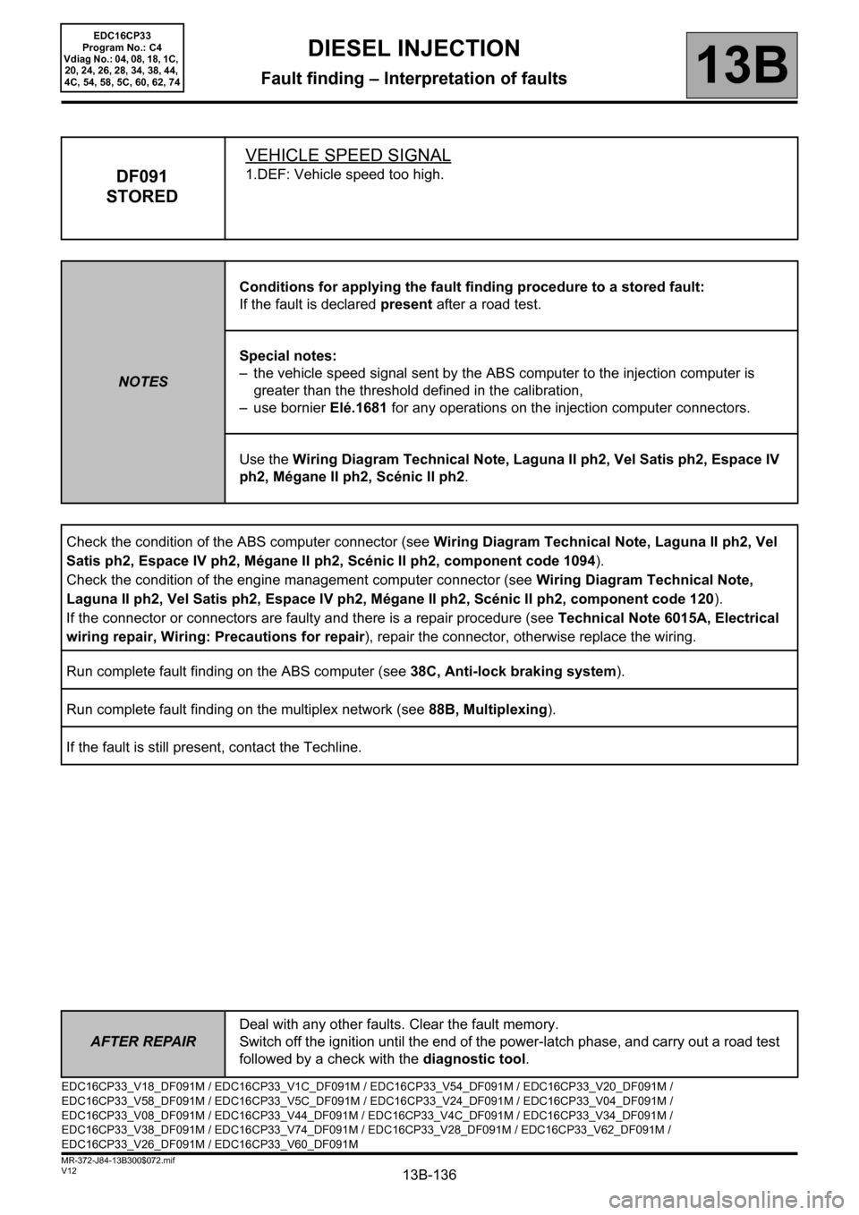
DF091
STOREDVEHICLE SPEED SIGNAL1.DEF: Vehicle speed too high.
NOTESConditions for applying the fault finding procedure to a stored fault:
If the fault is declared present after a road test.
Special notes:
– the vehicle speed signal sent by the ABS computer to the injection computer is
greater than the threshold defined in the calibration,
–use bornier Elé.1681 for any operations on the injection computer connectors.
Use the Wiring Diagram Technical Note, Laguna II ph2, Vel Satis ph2, Espace IV
ph2, Mégane II ph2, Scénic II ph2.
Check the condition of the ABS computer connector (see Wiring Diagram Technical Note, Laguna II ph2, Vel
Satis ph2, Espace IV ph2, Mégane II ph2, Scénic II ph2, component code 1094).
Check the condition of the engine management computer connector (see Wiring Diagram Technical Note,
Laguna II ph2, Vel Satis ph2, Espace IV ph2, Mégane II ph2, Scénic II ph2, component code 120).
If the connector or connectors are faulty and there is a repair procedure (see Technical Note 6015A, Electrical
wiring repair, Wiring: Precautions for repair), repair the connector, otherwise replace the wiring.
Run complete fault finding on the ABS computer (see 38C, Anti-lock braking system).
Run complete fault finding on the multiplex network (see 88B, Multiplexing).
If the fault is still present, contact the Techline.
EDC16CP33_V18_DF091M / EDC16CP33_V1C_DF091M / EDC16CP33_V54_DF091M / EDC16CP33_V20_DF091M /
EDC16CP33_V58_DF091M / EDC16CP33_V5C_DF091M / EDC16CP33_V24_DF091M / EDC16CP33_V04_DF091M /
EDC16CP33_V08_DF091M / EDC16CP33_V44_DF091M / EDC16CP33_V4C_DF091M / EDC16CP33_V34_DF091M /
EDC16CP33_V38_DF091M / EDC16CP33_V74_DF091M / EDC16CP33_V28_DF091M / EDC16CP33_V62_DF091M /
EDC16CP33_V26_DF091M / EDC16CP33_V60_DF091M
Page 137 of 510
13B-137
AFTER REPAIRDeal with any other faults. Clear the fault memory.
Switch off the ignition until the end of the power-latch phase, and carry out a road test
followed by a check with the diagnostic tool.
V12 MR-372-J84-13B300$072.mif
DIESEL INJECTION
Fault finding – Interpretation of faults13B
EDC16CP33
Program No.: C4
Vdiag No.: 04, 08, 18, 1C,
20, 24, 26, 28, 34, 38, 44,
4C, 54, 58, 5C, 60, 62, 74
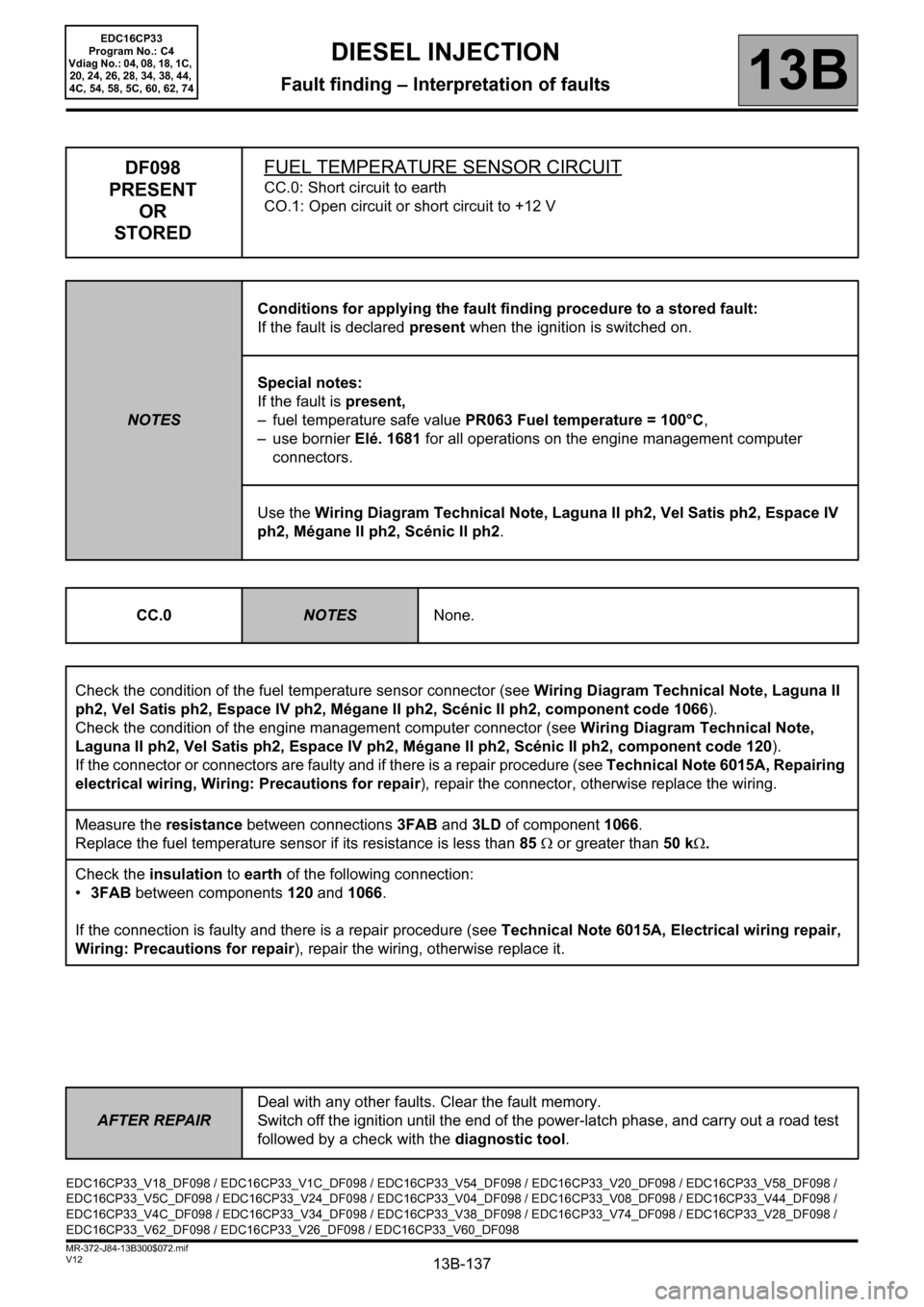
DF098
PRESENT
OR
STOREDFUEL TEMPERATURE SENSOR CIRCUIT
CC.0: Short circuit to earth
CO.1: Open circuit or short circuit to +12 V
NOTESConditions for applying the fault finding procedure to a stored fault:
If the fault is declared present when the ignition is switched on.
Special notes:
If the fault is present,
– fuel temperature safe value PR063 Fuel temperature = 100°C,
–use bornier Elé. 1681 for all operations on the engine management computer
connectors.
Use the Wiring Diagram Technical Note, Laguna II ph2, Vel Satis ph2, Espace IV
ph2, Mégane II ph2, Scénic II ph2.
CC.0
NOTESNone.
Check the condition of the fuel temperature sensor connector (see Wiring Diagram Technical Note, Laguna II
ph2, Vel Satis ph2, Espace IV ph2, Mégane II ph2, Scénic II ph2, component code 1066).
Check the condition of the engine management computer connector (see Wiring Diagram Technical Note,
Laguna II ph2, Vel Satis ph2, Espace IV ph2, Mégane II ph2, Scénic II ph2, component code 120).
If the connector or connectors are faulty and if there is a repair procedure (see Technical Note 6015A, Repairing
electrical wiring, Wiring: Precautions for repair), repair the connector, otherwise replace the wiring.
Measure the resistance between connections 3FAB and 3LD of component 1066.
Replace the fuel temperature sensor if its resistance is less than 85 Ω or greater than 50 kΩ.
Check the insulation to earth of the following connection:
•3FAB between components 120 and 1066.
If the connection is faulty and there is a repair procedure (see Technical Note 6015A, Electrical wiring repair,
Wiring: Precautions for repair), repair the wiring, otherwise replace it.
EDC16CP33_V18_DF098 / EDC16CP33_V1C_DF098 / EDC16CP33_V54_DF098 / EDC16CP33_V20_DF098 / EDC16CP33_V58_DF098 /
EDC16CP33_V5C_DF098 / EDC16CP33_V24_DF098 / EDC16CP33_V04_DF098 / EDC16CP33_V08_DF098 / EDC16CP33_V44_DF098 /
EDC16CP33_V4C_DF098 / EDC16CP33_V34_DF098 / EDC16CP33_V38_DF098 / EDC16CP33_V74_DF098 / EDC16CP33_V28_DF098 /
EDC16CP33_V62_DF098 / EDC16CP33_V26_DF098 / EDC16CP33_V60_DF098
Page 138 of 510
13B-138
AFTER REPAIRDeal with any other faults. Clear the fault memory.
Switch off the ignition until the end of the power-latch phase, and carry out a road test
followed by a check with the diagnostic tool.
V12 MR-372-J84-13B300$072.mif
DIESEL INJECTION
Fault finding – Interpretation of faults13B
EDC16CP33
Program No.: C4
Vdiag No.: 04, 08, 18, 1C,
20, 24, 26, 28, 34, 38, 44,
4C, 54, 58, 5C, 60, 62, 74
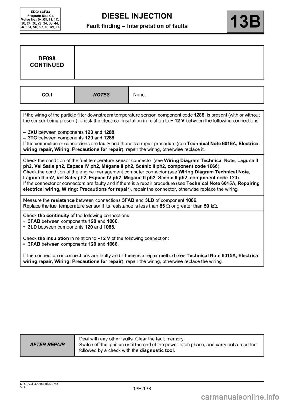
DF098
CONTINUED
CO.1NOTESNone.
If the wiring of the particle filter downstream temperature sensor, component code 1288, is present (with or without
the sensor being present), check the electrical insulation in relation to + 12 V between the following connections:
–3XU between components 120 and 1288,
–3TG between components 120 and 1288.
If the connection or connections are faulty and there is a repair procedure (see Technical Note 6015A, Electrical
wiring repair, Wiring: Precautions for repair), repair the wiring, otherwise replace it.
Check the condition of the fuel temperature sensor connector (see Wiring Diagram Technical Note, Laguna II
ph2, Vel Satis ph2, Espace IV ph2, Mégane II ph2, Scénic II ph2, component code 1066).
Check the condition of the engine management computer connector (see Wiring Diagram Technical Note,
Laguna II ph2, Vel Satis ph2, Espace IV ph2, Mégane II ph2, Scénic II ph2, component code 120).
If the connector or connectors are faulty and if there is a repair procedure (see Technical Note 6015A, Repairing
electrical wiring, Wiring: Precautions for repair), repair the connector, otherwise replace the wiring.
Measure the resistance between connections 3FAB and 3LD of component 1066.
Replace the fuel temperature sensor if its resistance is less than 85 Ω or greater than 50 kΩ.
Check the continuity of the following connections:
•3FAB between components 120 and 1066,
•3LD between components 120 and 1066.
Check the insulation in relation to +12 V of the following connection:
•3FAB between components 120 and 1066.
If the connection or connections are faulty and if there is a repair method (see Technical Note 6015A, Electrical
wiring repair, Wiring: Precautions for repair), repair the wiring, otherwise replace the wiring.
Page 140 of 510
13B-140
AFTER REPAIRDeal with any other faults. Clear the fault memory.
Switch off the ignition until the end of the power-latch phase, and carry out a road test
followed by a check with the diagnostic tool.
V12 MR-372-J84-13B300$072.mif
DIESEL INJECTION
Fault finding – Interpretation of faults13B
EDC16CP33
Program No.: C4
Vdiag No.: 04, 08, 18, 1C,
20, 24, 26, 28, 34, 38, 44,
4C, 54, 58, 5C, 60, 62, 74
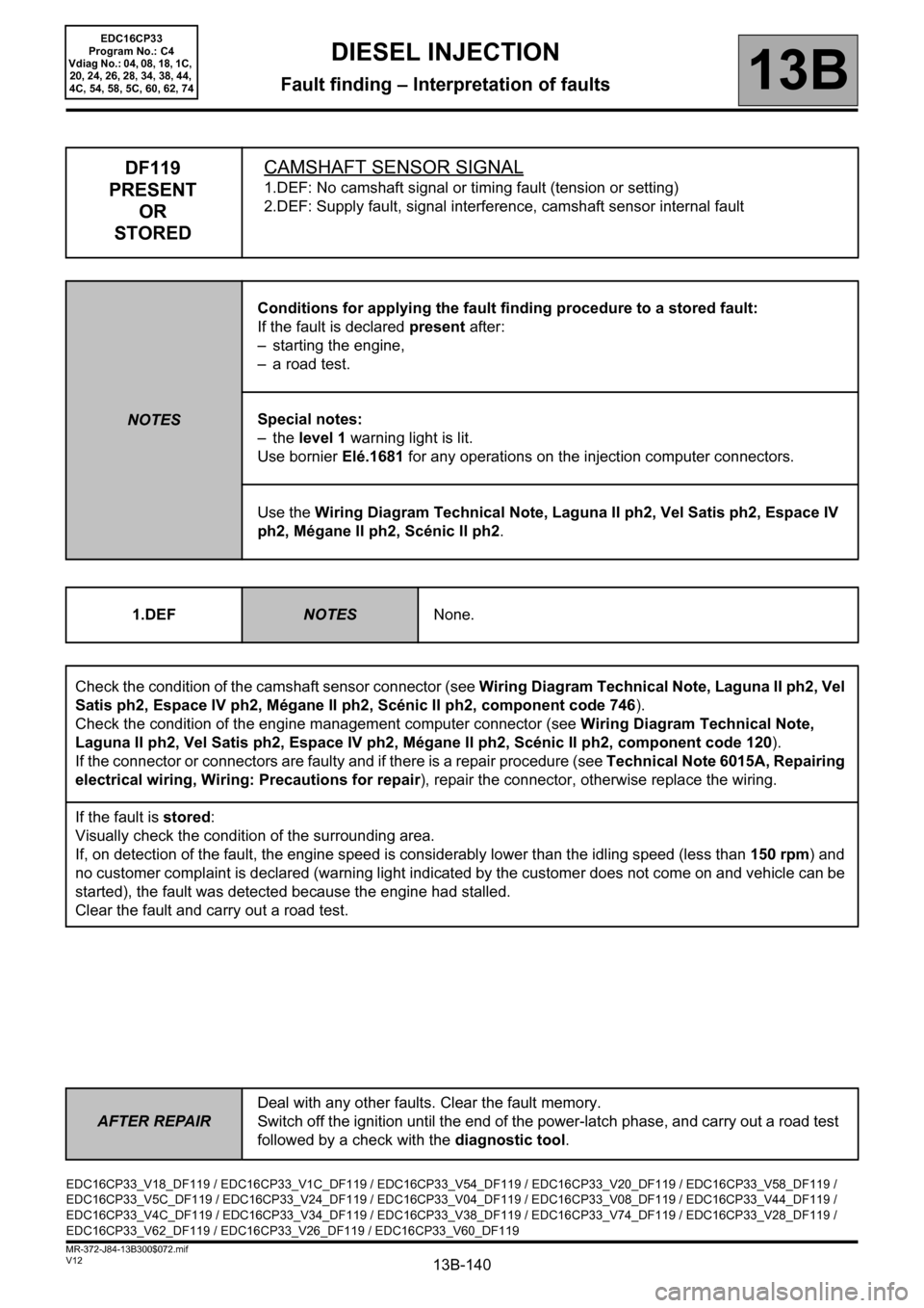
DF119
PRESENT
OR
STOREDCAMSHAFT SENSOR SIGNAL
1.DEF: No camshaft signal or timing fault (tension or setting)
2.DEF: Supply fault, signal interference, camshaft sensor internal fault
NOTESConditions for applying the fault finding procedure to a stored fault:
If the fault is declared present after:
– starting the engine,
– a road test.
Special notes:
–the level 1 warning light is lit.
Use bornier Elé.1681 for any operations on the injection computer connectors.
Use the Wiring Diagram Technical Note, Laguna II ph2, Vel Satis ph2, Espace IV
ph2, Mégane II ph2, Scénic II ph2.
1.DEF
NOTESNone.
Check the condition of the camshaft sensor connector (see Wiring Diagram Technical Note, Laguna II ph2, Vel
Satis ph2, Espace IV ph2, Mégane II ph2, Scénic II ph2, component code 746).
Check the condition of the engine management computer connector (see Wiring Diagram Technical Note,
Laguna II ph2, Vel Satis ph2, Espace IV ph2, Mégane II ph2, Scénic II ph2, component code 120).
If the connector or connectors are faulty and if there is a repair procedure (see Technical Note 6015A, Repairing
electrical wiring, Wiring: Precautions for repair), repair the connector, otherwise replace the wiring.
If the fault is stored:
Visually check the condition of the surrounding area.
If, on detection of the fault, the engine speed is considerably lower than the idling speed (less than 150 rpm) and
no customer complaint is declared (warning light indicated by the customer does not come on and vehicle can be
started), the fault was detected because the engine had stalled.
Clear the fault and carry out a road test.
EDC16CP33_V18_DF119 / EDC16CP33_V1C_DF119 / EDC16CP33_V54_DF119 / EDC16CP33_V20_DF119 / EDC16CP33_V58_DF119 /
EDC16CP33_V5C_DF119 / EDC16CP33_V24_DF119 / EDC16CP33_V04_DF119 / EDC16CP33_V08_DF119 / EDC16CP33_V44_DF119 /
EDC16CP33_V4C_DF119 / EDC16CP33_V34_DF119 / EDC16CP33_V38_DF119 / EDC16CP33_V74_DF119 / EDC16CP33_V28_DF119 /
EDC16CP33_V62_DF119 / EDC16CP33_V26_DF119 / EDC16CP33_V60_DF119
Page 141 of 510
13B-141
AFTER REPAIRDeal with any other faults. Clear the fault memory.
Switch off the ignition until the end of the power-latch phase, and carry out a road test
followed by a check with the diagnostic tool.
V12 MR-372-J84-13B300$072.mif
DIESEL INJECTION
Fault finding – Interpretation of faults13B
EDC16CP33
Program No.: C4
Vdiag No.: 04, 08, 18, 1C,
20, 24, 26, 28, 34, 38, 44,
4C, 54, 58, 5C, 60, 62, 74
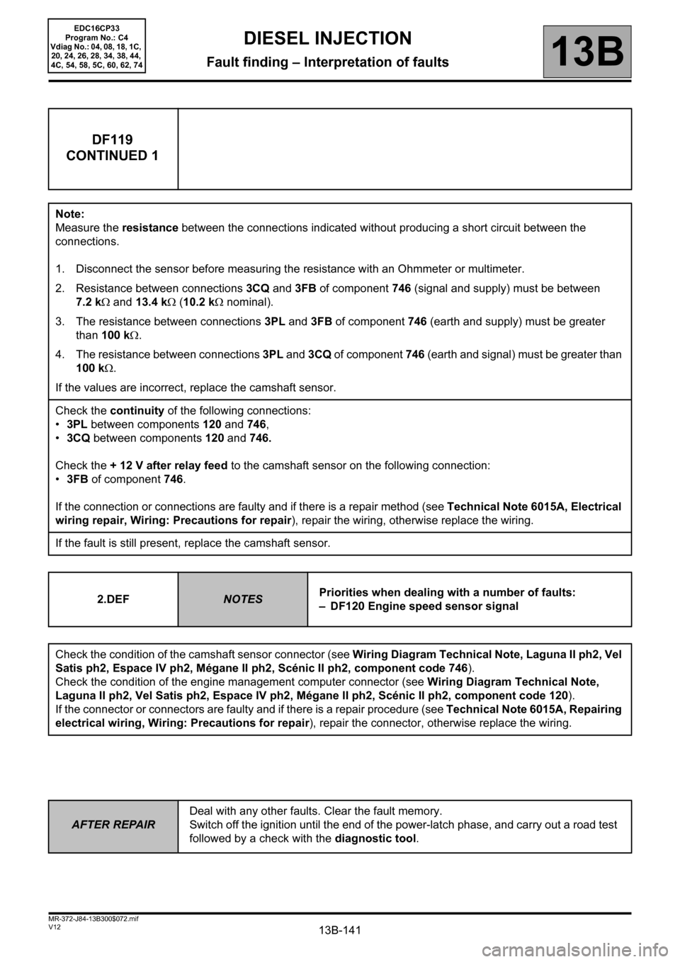
DF119
CONTINUED 1
Note:
Measure the resistance between the connections indicated without producing a short circuit between the
connections.
1. Disconnect the sensor before measuring the resistance with an Ohmmeter or multimeter.
2. Resistance between connections 3CQ and 3FB of component 746 (signal and supply) must be between
7.2 kΩ and 13.4 kΩ (10.2 kΩ nominal).
3. The resistance between connections 3PL and 3FB of component 746 (earth and supply) must be greater
than 100 kΩ.
4. The resistance between connections 3PL and 3CQ of component 746 (earth and signal) must be greater than
100 kΩ.
If the values are incorrect, replace the camshaft sensor.
Check the continuity of the following connections:
•3PL between components 120 and 746,
•3CQ between components 120 and 746.
Check the + 12 V after relay feed to the camshaft sensor on the following connection:
•3FB of component 746.
If the connection or connections are faulty and if there is a repair method (see Technical Note 6015A, Electrical
wiring repair, Wiring: Precautions for repair), repair the wiring, otherwise replace the wiring.
If the fault is still present, replace the camshaft sensor.
2.DEF
NOTESPriorities when dealing with a number of faults:
– DF120 Engine speed sensor signal
Check the condition of the camshaft sensor connector (see Wiring Diagram Technical Note, Laguna II ph2, Vel
Satis ph2, Espace IV ph2, Mégane II ph2, Scénic II ph2, component code 746).
Check the condition of the engine management computer connector (see Wiring Diagram Technical Note,
Laguna II ph2, Vel Satis ph2, Espace IV ph2, Mégane II ph2, Scénic II ph2, component code 120).
If the connector or connectors are faulty and if there is a repair procedure (see Technical Note 6015A, Repairing
electrical wiring, Wiring: Precautions for repair), repair the connector, otherwise replace the wiring.