WIRING DIAGRAM M9R RENAULT SCENIC 2012 J95 / 3.G Engine And Peripherals EDC16CP33 User Guide
[x] Cancel search | Manufacturer: RENAULT, Model Year: 2012, Model line: SCENIC, Model: RENAULT SCENIC 2012 J95 / 3.GPages: 510, PDF Size: 2.98 MB
Page 99 of 510

13B-99
AFTER REPAIRDeal with any other faults. Clear the fault memory.
Switch off the ignition until the end of the power-latch phase, and carry out a road test
followed by a check with the diagnostic tool.
V12 MR-372-J84-13B300$072.mif
DIESEL INJECTION
Fault finding – Interpretation of faults13B
EDC16CP33
Program No.: C4
Vdiag No.: 04, 08, 18, 1C,
20, 24, 26, 28, 34, 38, 44,
4C, 54, 58, 5C, 60, 62, 74
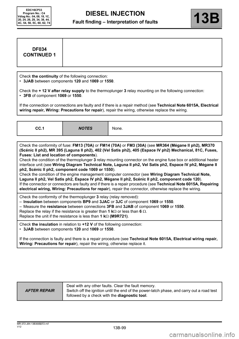
DF034
CONTINUED 1
Check the continuity of the following connection:
•3JAB between components 120 and 1069 or 1550.
Check the + 12 V after relay supply to the thermoplunger 3 relay mounting on the following connection:
•3FB of component 1069 or 1550.
If the connection or connections are faulty and if there is a repair method (see Technical Note 6015A, Electrical
wiring repair, Wiring: Precautions for repair), repair the wiring, otherwise replace the wiring.
CC.1
NOTESNone.
Check the conformity of fuse: FM13 (70A) or FM14 (70A) or FM3 (30A) (see MR364 (Mégane II ph2), MR370
(Scénic II ph2), MR 395 (Laguna II ph2), 402 (Vel Satis ph2), 405 (Espace IV ph2) Mechanical, 81C, Fuses,
Fuses: List and location of components).
Check the condition of the thermoplunger 3 relay mounting connector on the engine fuse box or additional heater
interface unit (see Wiring Diagram Technical Note, Laguna II ph2, Vel Satis ph2, Espace IV ph2, Mégane II
ph2, Scénic II ph2, component code 1069 or 1550).
Check the condition of the engine management computer connector (see Wiring Diagram Technical Note,
Laguna II ph2, Vel Satis ph2, Espace IV ph2, Mégane II ph2, Scénic II ph2, component code 120).
If the connector or connectors are faulty and if there is a repair procedure (see Technical Note 6015A, Repairing
electrical wiring, Wiring: Precautions for repair), repair the connector, otherwise replace the wiring.
Check the conformity of the thermoplunger 3 relay (relay removed):
–Insulation between components BP9 and 3JAC or 3JC of component 1069 or 1550.
– Measure the resistance between connections 3FB and 3JAB of component 1069 or 1550.
Replace the relay if the resistance is greater than 1 kΩ or less than 6 Ω.
Replace the unit if the resistance is less than 1 kΩ (M9R721).
Check the insulation in relation to +12 V of the following connection:
•3JAB between components 120 and 1069 or 1550.
If the connection is faulty and there is a repair procedure (see Technical Note 6015A, Electrical wiring repair,
Wiring: Precautions for repair), repair the wiring, otherwise replace it.
Page 100 of 510

13B-100
AFTER REPAIRDeal with any other faults. Clear the fault memory.
Switch off the ignition until the end of the power-latch phase, and carry out a road test
followed by a check with the diagnostic tool.
V12 MR-372-J84-13B300$072.mif
DIESEL INJECTION
Fault finding – Interpretation of faults13B
EDC16CP33
Program No.: C4
Vdiag No.: 04, 08, 18, 1C,
20, 24, 26, 28, 34, 38, 44,
4C, 54, 58, 5C, 60, 62, 74
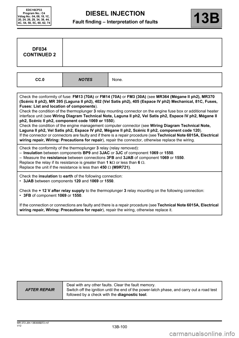
DF034
CONTINUED 2
CC.0NOTESNone.
Check the conformity of fuse: FM13 (70A) or FM14 (70A) or FM3 (30A) (see MR364 (Mégane II ph2), MR370
(Scénic II ph2), MR 395 (Laguna II ph2), 402 (Vel Satis ph2), 405 (Espace IV ph2) Mechanical, 81C, Fuses,
Fuses: List and location of components).
Check the condition of the thermoplunger 3 relay mounting connector on the engine fuse box or additional heater
interface unit (see Wiring Diagram Technical Note, Laguna II ph2, Vel Satis ph2, Espace IV ph2, Mégane II
ph2, Scénic II ph2, component code 1069 or 1550).
Check the condition of the engine management computer connector (see Wiring Diagram Technical Note,
Laguna II ph2, Vel Satis ph2, Espace IV ph2, Mégane II ph2, Scénic II ph2, component code 120).
If the connector or connectors are faulty and if there is a repair procedure (see Technical Note 6015A, Electrical
wiring repair, Wiring: Precautions for repair), repair the connector, otherwise replace the wiring.
Check the conformity of the thermoplunger 3 relay (relay removed):
–Insulation between components BP9 and 3JAC or 3JC of component 1069 or 1550.
– Measure the resistance between connections 3FB and 3JAB of component 1069 or 1550.
Replace the relay if its resistance is greater than 1 kΩ or less than 6 Ω.
Replace the unit if the resistance is less than 450 Ω (M9R721).
Check the insulation to earth of the following connection:
•3JAB between components 120 and 1069 or 1550.
Check the + 12 V after relay supply to the thermoplunger 3 relay mounting on the following connection:
•3FB
of component 1069 or 1550.
If the connection or connections are faulty and there is a repair procedure (see Technical Note 6015A, Electrical
wiring repair, Wiring: Precautions for repair), repair the wiring, otherwise replace it.
Page 148 of 510

13B-148
AFTER REPAIRDeal with any other faults. Clear the fault memory.
Switch off the ignition until the end of the power-latch phase, and carry out a road test
followed by a check with the diagnostic tool.
V12 MR-372-J84-13B300$073.mif
DIESEL INJECTION
Fault finding – Interpretation of faults13B
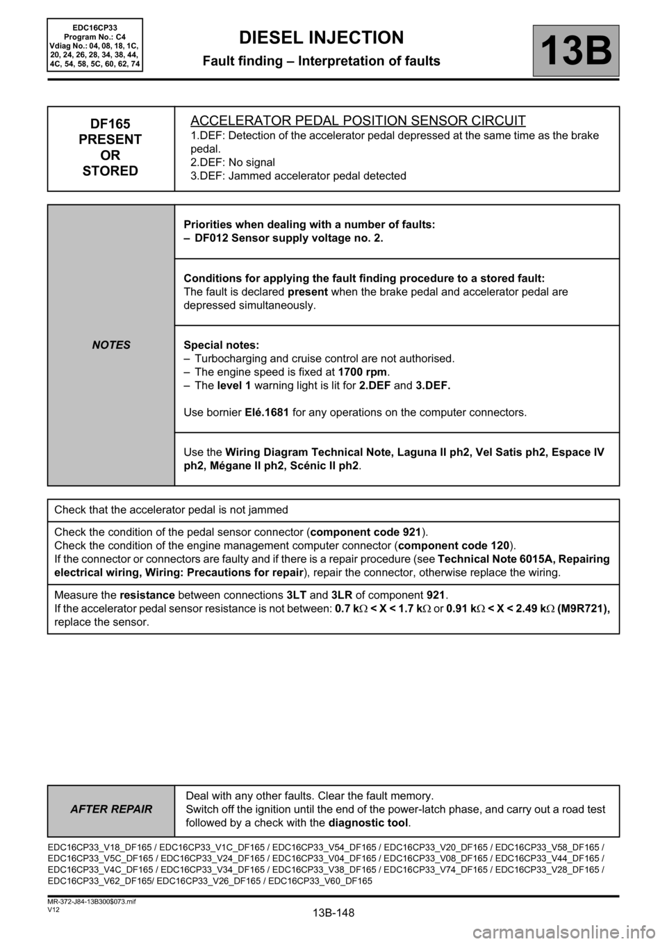
DF165
PRESENT
OR
STOREDACCELERATOR PEDAL POSITION SENSOR CIRCUIT1.DEF: Detection of the accelerator pedal depressed at the same time as the brake
pedal.
2.DEF: No signal
3.DEF: Jammed accelerator pedal detected
NOTESPriorities when dealing with a number of faults:
– DF012 Sensor supply voltage no. 2.
Conditions for applying the fault finding procedure to a stored fault:
The fault is declared present when the brake pedal and accelerator pedal are
depressed simultaneously.
Special notes:
– Turbocharging and cruise control are not authorised.
– The engine speed is fixed at 1700 rpm.
–The level 1 warning light is lit for 2.DEF and 3.DEF.
Use bornier Elé.1681 for any operations on the computer connectors.
Use the Wiring Diagram Technical Note, Laguna II ph2, Vel Satis ph2, Espace IV
ph2, Mégane II ph2, Scénic II ph2.
Check that the accelerator pedal is not jammed
Check the condition of the pedal sensor connector (component code 921).
Check the condition of the engine management computer connector (component code 120).
If the connector or connectors are faulty and if there is a repair procedure (see Technical Note 6015A, Repairing
electrical wiring, Wiring: Precautions for repair), repair the connector, otherwise replace the wiring.
Measure the resistance between connections 3LT and 3LR of component 921.
If the accelerator pedal sensor resistance is not between: 0.7 kΩ < X < 1.7 kΩ or 0.91 kΩ < X < 2.49 kΩ (M9R721),
replace the sensor.
EDC16CP33_V18_DF165 / EDC16CP33_V1C_DF165 / EDC16CP33_V54_DF165 / EDC16CP33_V20_DF165 / EDC16CP33_V58_DF165 /
EDC16CP33_V5C_DF165 / EDC16CP33_V24_DF165 / EDC16CP33_V04_DF165 / EDC16CP33_V08_DF165 / EDC16CP33_V44_DF165 /
EDC16CP33_V4C_DF165 / EDC16CP33_V34_DF165 / EDC16CP33_V38_DF165 / EDC16CP33_V74_DF165 / EDC16CP33_V28_DF165 /
EDC16CP33_V62_DF165/ EDC16CP33_V26_DF165 / EDC16CP33_V60_DF165
EDC16CP33
Program No.: C4
Vdiag No.: 04, 08, 18, 1C,
20, 24, 26, 28, 34, 38, 44,
4C, 54, 58, 5C, 60, 62, 74