WIRING DIAGRAM M9R RENAULT SCENIC 2012 J95 / 3.G Engine And Peripherals EDC16CP33 Workshop Manual
[x] Cancel search | Manufacturer: RENAULT, Model Year: 2012, Model line: SCENIC, Model: RENAULT SCENIC 2012 J95 / 3.GPages: 510, PDF Size: 2.98 MB
Page 2 of 510
13B-2V12 MR-372-J84-13B300$010.mif
13B
EDC16CP33
Program No.: C4
Vdiag No.: 04, 08, 18, 1C,
20, 24, 26, 28, 34, 38, 44,
4C, 54, 58, 5C, 60, 62, 74
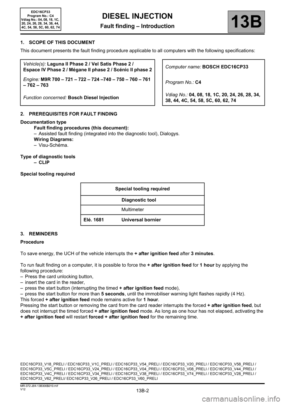
1. SCOPE OF THIS DOCUMENT
This document presents the fault finding procedure applicable to all computers with the following specifications:
2. PREREQUISITES FOR FAULT FINDING
Documentation type
Fault finding procedures (this document):
– Assisted fault finding (integrated into the diagnostic tool), Dialogys.
Wiring Diagrams:
–Visu-Schéma.
Type of diagnostic tools
–CLIP
Special tooling required
3. REMINDERS
Procedure
To save energy, the UCH of the vehicle interrupts the + after ignition feed after 3 minutes.
To run fault finding on a computer, it is possible to force the + after ignition feed for 1 hour by applying the
following procedure:
– Press the card unlocking button,
– insert the card in the reader,
– press the start button (interrupting the timed + after ignition feed mode),
– press the start button for more than 5 seconds, until the immobiliser warning light flashes rapidly (4 Hz).
This forced + after ignition feed mode remains active for 1 hour.
Pressing the start button or removing the card from the card reader interrupts the forced + after ignition feed, but
does not interrupt the timed forced + after ignition feed mode. As long as one hour has not elapsed, activating the
+ after ignition feed will restart forced + after ignition feed for the remaining time. Vehicle(s): Laguna II Phase 2 / Vel Satis Phase 2 /
Espace IV Phase 2 / Mégane II phase 2 / Scénic II phase 2Computer name: BOSCH EDC16CP33
Engine: M9R 700 – 721 – 722 – 724 –740 – 750 – 760 – 761
– 762 – 763Program No.: C4
Function concerned: Bosch Diesel InjectionVdiag No.: 04, 08, 18, 1C, 20, 24, 26, 28, 34,
38, 44, 4C, 54, 58, 5C, 60, 62, 74
Special tooling required
Diagnostic tool
Multimeter
Elé. 1681 Universal bornier
EDC16CP33_V18_PRELI / EDC16CP33_V1C_PRELI / EDC16CP33_V54_PRELI / EDC16CP33_V20_PRELI / EDC16CP33_V58_PRELI /
EDC16CP33_V5C_PRELI / EDC16CP33_V24_PRELI / EDC16CP33_V04_PRELI / EDC16CP33_V08_PRELI / EDC16CP33_V44_PRELI /
EDC16CP33_V4C_PRELI / EDC16CP33_V34_PRELI / EDC16CP33_V38_PRELI / EDC16CP33_V74_PRELI / EDC16CP33_V28_PRELI /
EDC16CP33_V62_PRELI/ EDC16CP33_V26_PRELI / EDC16CP33_V60_PRELI
DIESEL INJECTION
Fault finding – Introduction
Page 70 of 510
13B-70
AFTER REPAIRDeal with any other faults. Clear the fault memory.
Switch off the ignition until the end of the power-latch phase, and carry out a road test
followed by a check with the diagnostic tool.
V12 MR-372-J84-13B300$071.mif
DIESEL INJECTION
Fault finding – Interpretation of faults13B
EDC16CP33
Program No.: C4
Vdiag No.: 04, 08, 18, 1C,
20, 24, 26, 28, 34, 38, 44,
4C, 54, 58, 5C, 60, 62, 74
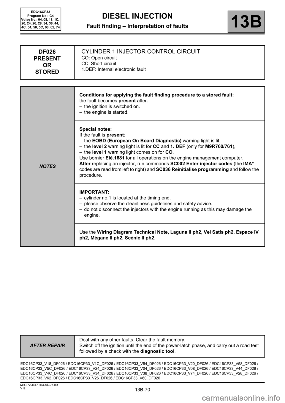
DF026
PRESENT
OR
STOREDCYLINDER 1 INJECTOR CONTROL CIRCUIT
CO: Open circuit
CC: Short circuit
1.DEF: Internal electronic fault
NOTESConditions for applying the fault finding procedure to a stored fault:
the fault becomes present after:
– the ignition is switched on.
– the engine is started.
Special notes:
If the fault is present:
–the EOBD (European On Board Diagnostic) warning light is lit,
–the level 2 warning light is lit for CC and 1. DEF (only for M9R760/761),
–the level 1 warning light comes on for CO.
Use bornier Elé.1681 for all operations on the engine management computer.
After replacing an injector, run commands SC002 Enter injector codes (the IMA*
codes are read from left to right) and SC036 Reinitialise programming and follow the
procedure.
IMPORTANT:
– cylinder no.1 is located at the timing end.
– please observe the cleanliness guidelines and safety advice.
– do not disconnect the injectors with the engine running as this may damage the
engine.
Use the Wiring Diagram Technical Note, Laguna II ph2, Vel Satis ph2, Espace IV
ph2, Mégane II ph2, Scénic II ph2.
EDC16CP33_V18_DF026 / EDC16CP33_V1C_DF026 / EDC16CP33_V54_DF026 / EDC16CP33_V20_DF026 / EDC16CP33_V58_DF026 /
EDC16CP33_V5C_DF026 / EDC16CP33_V24_DF026 / EDC16CP33_V04_DF026 / EDC16CP33_V08_DF026 / EDC16CP33_V44_DF026 /
EDC16CP33_V4C_DF026 / EDC16CP33_V34_DF026 / EDC16CP33_V38_DF026 / EDC16CP33_V74_DF026 / EDC16CP33_V28_DF026 /
EDC16CP33_V62_DF026 / EDC16CP33_V26_DF026 / EDC16CP33_V60_DF026
Page 90 of 510
13B-90
AFTER REPAIRDeal with any other faults. Clear the fault memory.
Switch off the ignition until the end of the power-latch phase, and carry out a road test
followed by a check with the diagnostic tool.
V12 MR-372-J84-13B300$071.mif
DIESEL INJECTION
Fault finding – Interpretation of faults13B
EDC16CP33
Program No.: C4
Vdiag No.: 04, 08, 18, 1C,
20, 24, 26, 28, 34, 38, 44,
4C, 54, 58, 5C, 60, 62, 74
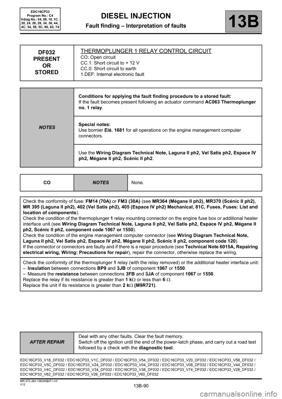
DF032
PRESENT
OR
STOREDTHERMOPLUNGER 1 RELAY CONTROL CIRCUITCO: Open circuit
CC.1: Short circuit to + 12 V
CC.0: Short circuit to earth
1.DEF: Internal electronic fault
NOTESConditions for applying the fault finding procedure to a stored fault:
If the fault becomes present following an actuator command AC063 Thermoplunger
no. 1 relay.
Special notes:
Use bornier Elé. 1681 for all operations on the engine management computer
connectors.
Use the Wiring Diagram Technical Note, Laguna II ph2, Vel Satis ph2, Espace IV
ph2, Mégane II ph2, Scénic II ph2.
CO
NOTESNone.
Check the conformity of fuse: FM14 (70A) or FM3 (30A) (see MR364 (Mégane II ph2), MR370 (Scénic II ph2),
MR 395 (Laguna II ph2), 402 (Vel Satis ph2), 405 (Espace IV ph2) Mechanical, 81C, Fuses, Fuses: List and
location of components).
Check the condition of the thermoplunger 1 relay mounting connector on the engine fuse box or additional heater
interface unit (see Wiring Diagram Technical Note, Laguna II ph2, Vel Satis ph2, Espace IV ph2, Mégane II
ph2, Scénic II ph2, component code 1067 or 1550).
Check the condition of the engine management computer connector (see Wiring Diagram Technical Note,
Laguna II ph2, Vel Satis ph2, Espace IV ph2, Mégane II ph2, Scénic II ph2, component code 120).
If the connector or connectors are faulty and if there is a repair procedure (see Technical Note 6015A, Repairing
electrical wiring, Wiring: Precautions for repair), repair the connector, otherwise replace the wiring.
Check the conformity of the thermoplunger 1 relay (with the relay removed) or the additional heater interface unit:
–Insulation between connections BP9 and 3JB of component 1067 or 1550.
– Measure the resistance between connections3FB and 3JA of component1067 or 1550.
Replace the relay if its resistance is greater than 1 kΩ or less than 6 Ω.
Replace the unit if its resistance is greater than 2 kΩ (M9R721).
EDC16CP33_V18_DF032 / EDC16CP33_V1C_DF032 / EDC16CP33_V54_DF032 / EDC16CP33_V20_DF032 / EDC16CP33_V58_DF032 /
EDC16CP33_V5C_DF032 / EDC16CP33_V24_DF032 / EDC16CP33_V04_DF032 / EDC16CP33_V08_DF032 / EDC16CP33_V44_DF032 /
EDC16CP33_V4C_DF032 / EDC16CP33_V34_DF032 / EDC16CP33_V38_DF032 / EDC16CP33_V74_DF032 / EDC16CP33_V28_DF032 /
EDC16CP33_V62_DF032 / EDC16CP33_V26_DF032 / EDC16CP33_V60_DF032
Page 91 of 510
13B-91
AFTER REPAIRDeal with any other faults. Clear the fault memory.
Switch off the ignition until the end of the power-latch phase, and carry out a road test
followed by a check with the diagnostic tool.
V12 MR-372-J84-13B300$071.mif
DIESEL INJECTION
Fault finding – Interpretation of faults13B
EDC16CP33
Program No.: C4
Vdiag No.: 04, 08, 18, 1C,
20, 24, 26, 28, 34, 38, 44,
4C, 54, 58, 5C, 60, 62, 74
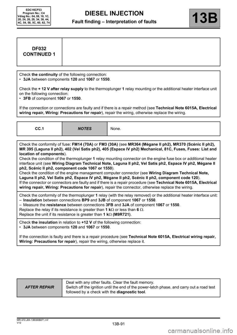
DF032
CONTINUED 1
Check the continuity of the following connection:
•3JA between components 120 and 1067 or 1550.
Check the + 12 V after relay supply to the thermoplunger 1 relay mounting or the additional heater interface unit
on the following connection:
•3FB of component 1067 or 1550.
If the connection or connections are faulty and if there is a repair method (see Technical Note 6015A, Electrical
wiring repair, Wiring: Precautions for repair), repair the wiring, otherwise replace the wiring.
CC.1
NOTESNone.
Check the conformity of fuse: FM14 (70A) or FM3 (30A) (see MR364 (Mégane II ph2), MR370 (Scénic II ph2),
MR 395 (Laguna II ph2), 402 (Vel Satis ph2), 405 (Espace IV ph2) Mechanical, 81C, Fuses, Fuses: List and
location of components).
Check the condition of the thermoplunger 1 relay mounting connector on the engine fuse box or additional heater
interface unit (see Wiring Diagram Technical Note, Laguna II ph2, Vel Satis ph2, Espace IV ph2, Mégane II
ph2, Scénic II ph2, component code 1067 or 1550).
Check the condition of the engine management computer connector (see Wiring Diagram Technical Note,
Laguna II ph2, Vel Satis ph2, Espace IV ph2, Mégane II ph2, Scénic II ph2, component code 120).
If the connector or connectors are faulty and if there is a repair procedure (see Technical Note 6015A, Electrical
wiring repair, Wiring: Precautions for repair), repair the connector, otherwise replace the wiring.
Check the conformity of the thermoplunger 1 relay (with the relay removed) or the additional heater interface unit:
–Insulation between connections BP9 and 3JB of component 1067 or 1550.
– Measure the resistance between connections3FB and 3JA of component1067 or 1550.
Replace the relay if its resistance is greater than 1 kΩ or less than 6 Ω.
Replace the unit if its resistance is greater than 1 kΩ (M9R721).
Check the insulation in relation to +12 V of the following connection:
•3JA between components 120 and 1067 or 1550.
If the connection is faulty and there is a repair procedure (see Technical Note 6015A, Electrical wiring repair,
Wiring: Precautions for repair), repair the wiring, otherwise replace it.
Page 92 of 510
13B-92
AFTER REPAIRDeal with any other faults. Clear the fault memory.
Switch off the ignition until the end of the power-latch phase, and carry out a road test
followed by a check with the diagnostic tool.
V12 MR-372-J84-13B300$071.mif
DIESEL INJECTION
Fault finding – Interpretation of faults13B
EDC16CP33
Program No.: C4
Vdiag No.: 04, 08, 18, 1C,
20, 24, 26, 28, 34, 38, 44,
4C, 54, 58, 5C, 60, 62, 74
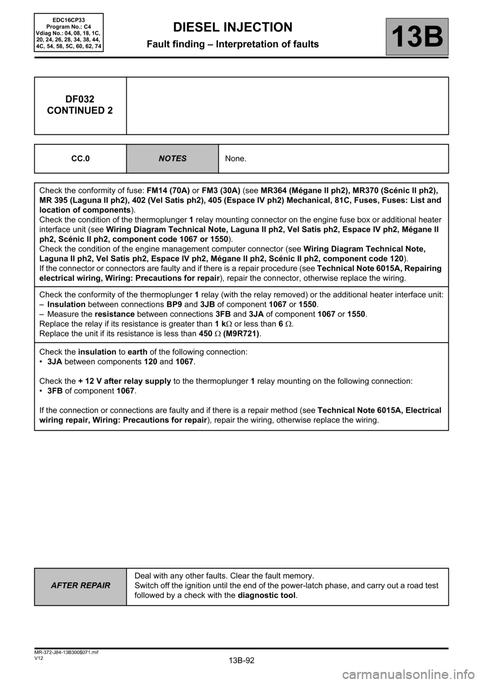
DF032
CONTINUED 2
CC.0NOTESNone.
Check the conformity of fuse: FM14 (70A) or FM3 (30A) (see MR364 (Mégane II ph2), MR370 (Scénic II ph2),
MR 395 (Laguna II ph2), 402 (Vel Satis ph2), 405 (Espace IV ph2) Mechanical, 81C, Fuses, Fuses: List and
location of components).
Check the condition of the thermoplunger 1 relay mounting connector on the engine fuse box or additional heater
interface unit (see Wiring Diagram Technical Note, Laguna II ph2, Vel Satis ph2, Espace IV ph2, Mégane II
ph2, Scénic II ph2, component code 1067 or 1550).
Check the condition of the engine management computer connector (see Wiring Diagram Technical Note,
Laguna II ph2, Vel Satis ph2, Espace IV ph2, Mégane II ph2, Scénic II ph2, component code 120).
If the connector or connectors are faulty and if there is a repair procedure (see Technical Note 6015A, Repairing
electrical wiring, Wiring: Precautions for repair), repair the connector, otherwise replace the wiring.
Check the conformity of the thermoplunger 1 relay (with the relay removed) or the additional heater interface unit:
–Insulation between connections BP9 and 3JB of component 1067 or 1550.
– Measure the resistance between connections3FB and 3JA of component1067 or 1550.
Replace the relay if its resistance is greater than 1 kΩ or less than 6 Ω.
Replace the unit if its resistance is less than 450 Ω (M9R721).
Check the insulation to earth of the following connection:
•3JA between components 120 and 1067.
Check the + 12 V after relay supply to the thermoplunger 1 relay mounting on the following connection:
•3FB of component 1067.
If the connection or connections are faulty and if there is a repair method (see Technical Note 6015A, Electrical
wiring repair, Wiring: Precautions for repair), repair the wiring, otherwise replace the wiring.
Page 93 of 510
13B-93
AFTER REPAIRDeal with any other faults. Clear the fault memory.
Switch off the ignition until the end of the power-latch phase, and carry out a road test
followed by a check with the diagnostic tool.
V12 MR-372-J84-13B300$071.mif
DIESEL INJECTION
Fault finding – Interpretation of faults13B
EDC16CP33
Program No.: C4
Vdiag No.: 04, 08, 18, 1C,
20, 24, 26, 28, 34, 38, 44,
4C, 54, 58, 5C, 60, 62, 74
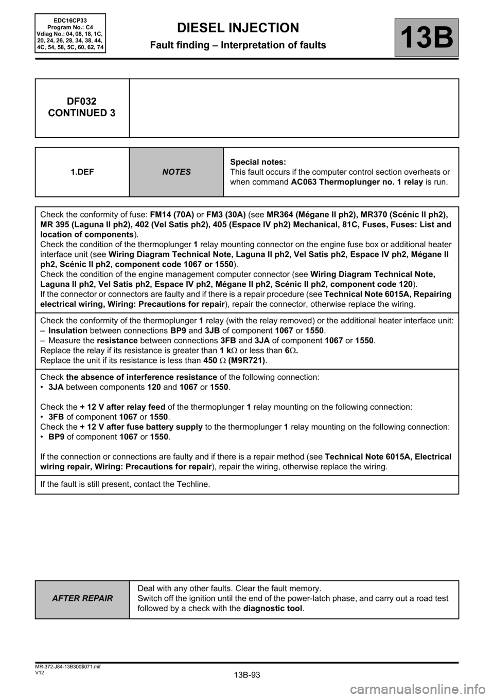
DF032
CONTINUED 3
1.DEFNOTESSpecial notes:
This fault occurs if the computer control section overheats or
when command AC063 Thermoplunger no. 1 relay is run.
Check the conformity of fuse: FM14 (70A) or FM3 (30A) (see MR364 (Mégane II ph2), MR370 (Scénic II ph2),
MR 395 (Laguna II ph2), 402 (Vel Satis ph2), 405 (Espace IV ph2) Mechanical, 81C, Fuses, Fuses: List and
location of components).
Check the condition of the thermoplunger 1 relay mounting connector on the engine fuse box or additional heater
interface unit (see Wiring Diagram Technical Note, Laguna II ph2, Vel Satis ph2, Espace IV ph2, Mégane II
ph2, Scénic II ph2, component code 1067 or 1550).
Check the condition of the engine management computer connector (see Wiring Diagram Technical Note,
Laguna II ph2, Vel Satis ph2, Espace IV ph2, Mégane II ph2, Scénic II ph2, component code 120).
If the connector or connectors are faulty and if there is a repair procedure (see Technical Note 6015A, Repairing
electrical wiring, Wiring: Precautions for repair), repair the connector, otherwise replace the wiring.
Check the conformity of the thermoplunger 1 relay (with the relay removed) or the additional heater interface unit:
–Insulation between connections BP9 and 3JB of component 1067 or 1550.
– Measure the resistance between connections3FB and 3JA of component1067 or 1550.
Replace the relay if its resistance is greater than 1 kΩ or less than 6Ω.
Replace the unit if its resistance is less than 450 Ω (M9R721).
Check the absence of interference resistance of the following connection:
•3JA between components 120 and 1067 or 1550.
Check the + 12 V after relay feed of the thermoplunger 1 relay mounting on the following connection:
•3FB of component 1067 or
1550.
Check the + 12 V after fuse battery supply to the thermoplunger 1 relay mounting on the following connection:
•BP9 of component 1067 or 1550.
If the connection or connections are faulty and if there is a repair method (see Technical Note 6015A, Electrical
wiring repair, Wiring: Precautions for repair), repair the wiring, otherwise replace the wiring.
If the fault is still present, contact the Techline.
Page 94 of 510
13B-94
AFTER REPAIRDeal with any other faults. Clear the fault memory.
Switch off the ignition until the end of the power-latch phase, and carry out a road test
followed by a check with the diagnostic tool.
V12 MR-372-J84-13B300$072.mif
13B
EDC16CP33
Program No.: C4
Vdiag No.: 04, 08, 18, 1C,
20, 24, 26, 28, 34, 38, 44,
4C, 54, 58, 5C, 60, 62, 74
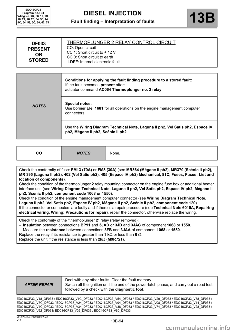
DF033
PRESENT
OR
STOREDTHERMOPLUNGER 2 RELAY CONTROL CIRCUITCO: Open circuit
CC.1: Short circuit to + 12 V
CC.0: Short circuit to earth
1.DEF: Internal electronic fault
NOTESConditions for applying the fault finding procedure to a stored fault:
If the fault becomes present after:
actuator command AC064 Thermoplunger no. 2 relay.
Special notes:
Use bornier Elé. 1681 for all operations on the engine management computer
connectors.
Use the Wiring Diagram Technical Note, Laguna II ph2, Vel Satis ph2, Espace IV
ph2, Mégane II ph2, Scénic II ph2.
CO
NOTESNone.
Check the conformity of fuse: FM13 (70A) or FM3 (30A) (see MR364 (Mégane II ph2), MR370 (Scénic II ph2),
MR 395 (Laguna II ph2), 402 (Vel Satis ph2), 405 (Espace IV ph2) Mechanical, 81C, Fuses, Fuses: List and
location of components).
Check the condition of the thermoplunger 2 relay mounting connector on the engine fuse box or additional heater
interface unit (see Wiring Diagram Technical Note, Laguna II ph2, Vel Satis ph2, Espace IV ph2, Mégane II
ph2, Scénic II ph2, component code 1068 or 1550).
Check the condition of the engine management computer connector (see Wiring Diagram Technical Note,
Laguna II ph2, Vel Satis ph2, Espace IV ph2, Mégane II ph2, Scénic II ph2, component code 120).
If the connector or connectors are faulty and if there is a repair procedure (see Technical Note 6015A, Repairing
electrical wiring, Wiring: Precautions for repair), repair the connector, otherwise replace the wiring.
Check the conformity of the "thermoplunger 2" relay (relay removed):
–Insulation between connections BP91 and 3JAD or 3JD and 3JAC of component 1068 or 1550.
– Measure the resistance between connections3FB and 3JAA of component 1068 or 1550.
Replace the relay if its resistance is greater than 1 kΩ or less than 6 Ω.
Replace the unit if the resistance is less than 2kΩ (M9R721).
EDC16CP33_V18_DF033 / EDC16CP33_V1C_DF033 / EDC16CP33_V54_DF033 / EDC16CP33_V20_DF033 / EDC16CP33_V58_DF033 /
EDC16CP33_V5C_DF033 / EDC16CP33_V24_DF033 / EDC16CP33_V04_DF033 / EDC16CP33_V08_DF033 / EDC16CP33_V44_DF033 /
EDC16CP33_V4C_DF033 / EDC16CP33_V34_DF033 / EDC16CP33_V38_DF033 / EDC16CP33_V74_DF033 / EDC16CP33_V28_DF033 /
EDC16CP33_V62_DF033/ EDC16CP33_V26_DF033 / EDC16CP33_V60_DF033
DIESEL INJECTION
Fault finding – Interpretation of faults
Page 95 of 510
13B-95
AFTER REPAIRDeal with any other faults. Clear the fault memory.
Switch off the ignition until the end of the power-latch phase, and carry out a road test
followed by a check with the diagnostic tool.
V12 MR-372-J84-13B300$072.mif
DIESEL INJECTION
Fault finding – Interpretation of faults13B
EDC16CP33
Program No.: C4
Vdiag No.: 04, 08, 18, 1C,
20, 24, 26, 28, 34, 38, 44,
4C, 54, 58, 5C, 60, 62, 74
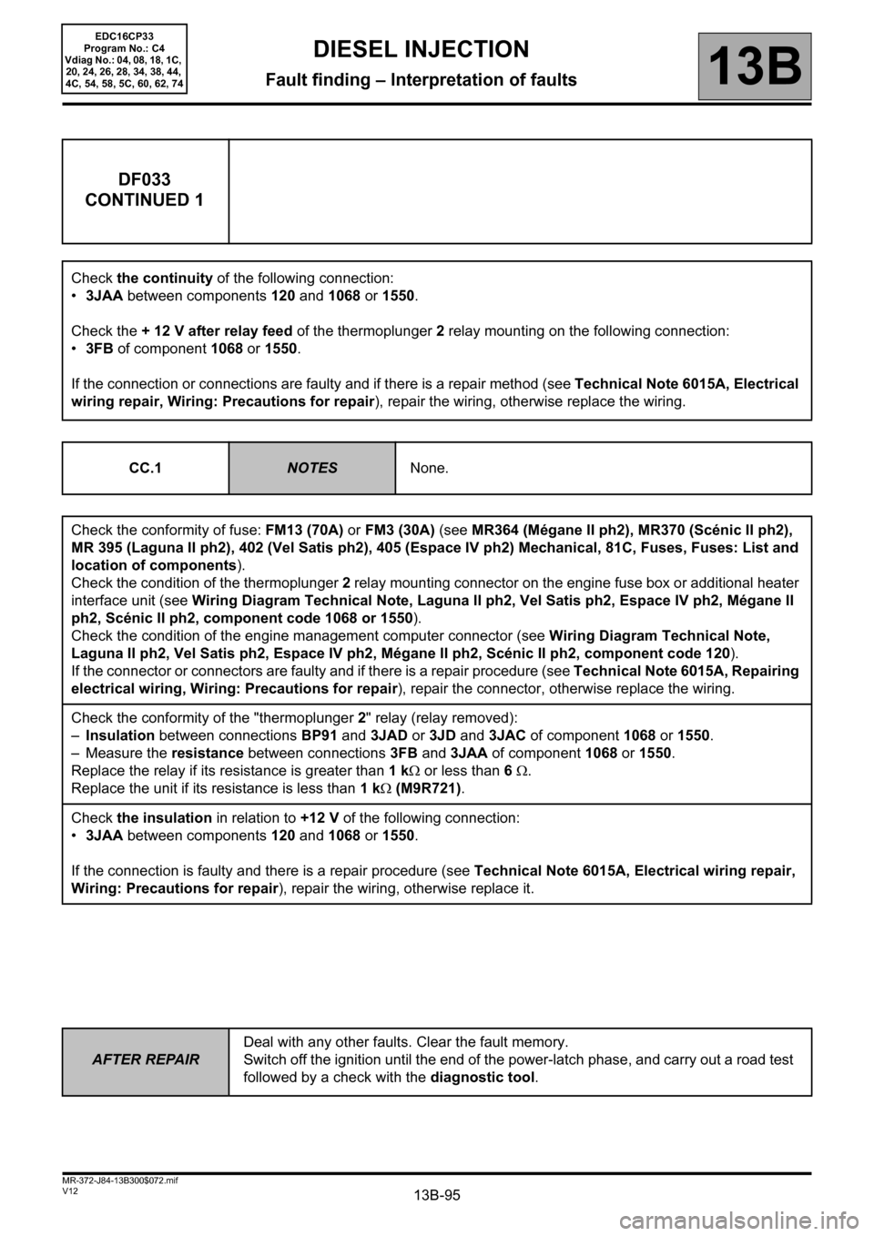
DF033
CONTINUED 1
Check the continuity of the following connection:
•3JAA between components 120 and 1068 or 1550.
Check the + 12 V after relay feed of the thermoplunger 2 relay mounting on the following connection:
•3FB of component 1068 or 1550.
If the connection or connections are faulty and if there is a repair method (see Technical Note 6015A, Electrical
wiring repair, Wiring: Precautions for repair), repair the wiring, otherwise replace the wiring.
CC.1
NOTESNone.
Check the conformity of fuse: FM13 (70A) or FM3 (30A) (see MR364 (Mégane II ph2), MR370 (Scénic II ph2),
MR 395 (Laguna II ph2), 402 (Vel Satis ph2), 405 (Espace IV ph2) Mechanical, 81C, Fuses, Fuses: List and
location of components).
Check the condition of the thermoplunger 2 relay mounting connector on the engine fuse box or additional heater
interface unit (see Wiring Diagram Technical Note, Laguna II ph2, Vel Satis ph2, Espace IV ph2, Mégane II
ph2, Scénic II ph2, component code 1068 or 1550).
Check the condition of the engine management computer connector (see Wiring Diagram Technical Note,
Laguna II ph2, Vel Satis ph2, Espace IV ph2, Mégane II ph2, Scénic II ph2, component code 120).
If the connector or connectors are faulty and if there is a repair procedure (see Technical Note 6015A, Repairing
electrical wiring, Wiring: Precautions for repair), repair the connector, otherwise replace the wiring.
Check the conformity of the "thermoplunger 2" relay (relay removed):
–Insulation between connections BP91 and 3JAD or 3JD and 3JAC of component 1068 or 1550.
– Measure the resistance between connections 3FB and 3JAA of component 1068 or 1550.
Replace the relay if its resistance is greater than 1 kΩ or less than 6 Ω.
Replace the unit if its resistance is less than 1 kΩ (M9R721).
Check the insulation in relation to +12 V of the following connection:
•3JAA between components 120 and 1068 or 1550.
If the connection is faulty and there is a repair procedure (see Technical Note 6015A, Electrical wiring repair,
Wiring: Precautions for repair), repair the wiring, otherwise replace it.
Page 96 of 510
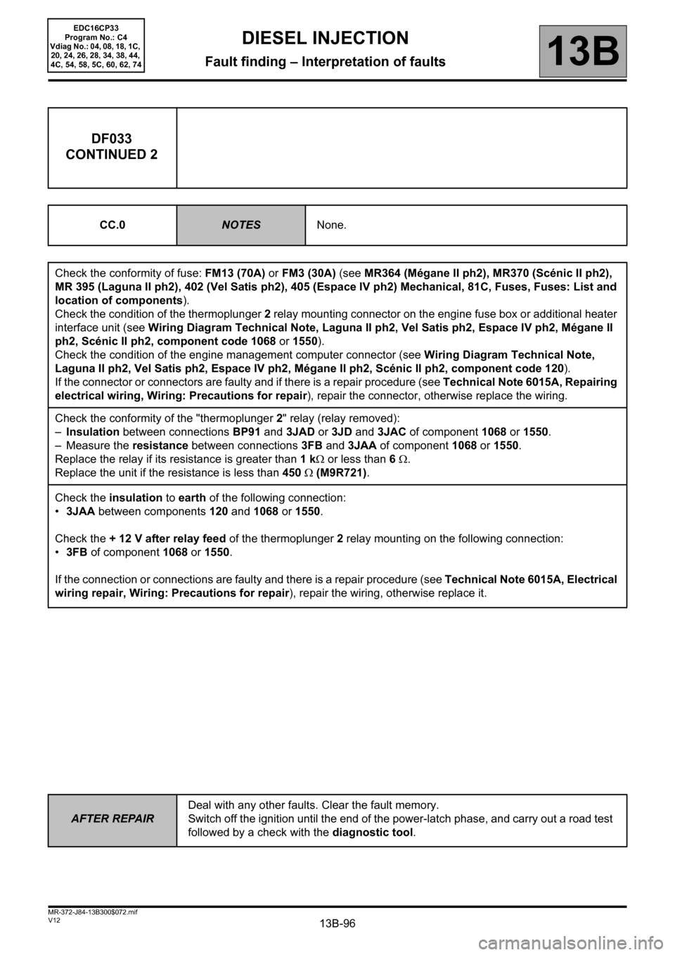
13B-96
AFTER REPAIRDeal with any other faults. Clear the fault memory.
Switch off the ignition until the end of the power-latch phase, and carry out a road test
followed by a check with the diagnostic tool.
V12 MR-372-J84-13B300$072.mif
DIESEL INJECTION
Fault finding – Interpretation of faults13B
EDC16CP33
Program No.: C4
Vdiag No.: 04, 08, 18, 1C,
20, 24, 26, 28, 34, 38, 44,
4C, 54, 58, 5C, 60, 62, 74
DF033
CONTINUED 2
CC.0NOTESNone.
Check the conformity of fuse: FM13 (70A) or FM3 (30A) (see MR364 (Mégane II ph2), MR370 (Scénic II ph2),
MR 395 (Laguna II ph2), 402 (Vel Satis ph2), 405 (Espace IV ph2) Mechanical, 81C, Fuses, Fuses: List and
location of components).
Check the condition of the thermoplunger 2 relay mounting connector on the engine fuse box or additional heater
interface unit (see Wiring Diagram Technical Note, Laguna II ph2, Vel Satis ph2, Espace IV ph2, Mégane II
ph2, Scénic II ph2, component code 1068 or 1550).
Check the condition of the engine management computer connector (see Wiring Diagram Technical Note,
Laguna II ph2, Vel Satis ph2, Espace IV ph2, Mégane II ph2, Scénic II ph2, component code 120).
If the connector or connectors are faulty and if there is a repair procedure (see Technical Note 6015A, Repairing
electrical wiring, Wiring: Precautions for repair), repair the connector, otherwise replace the wiring.
Check the conformity of the "thermoplunger 2" relay (relay removed):
–Insulation between connections BP91 and 3JAD or 3JD and 3JAC of component 1068 or 1550.
– Measure the resistance between connections 3FB and 3JAA of component 1068 or 1550.
Replace the relay if its resistance is greater than 1 kΩ or less than 6 Ω.
Replace the unit if the resistance is less than 450 Ω (M9R721).
Check the insulation to earth of the following connection:
•3JAA between components 120 and 1068 or 1550.
Check the + 12 V after relay feed of the thermoplunger 2 relay mounting on the following connection:
•
3FB of component 1068 or 1550.
If the connection or connections are faulty and there is a repair procedure (see Technical Note 6015A, Electrical
wiring repair, Wiring: Precautions for repair), repair the wiring, otherwise replace it.
Page 98 of 510
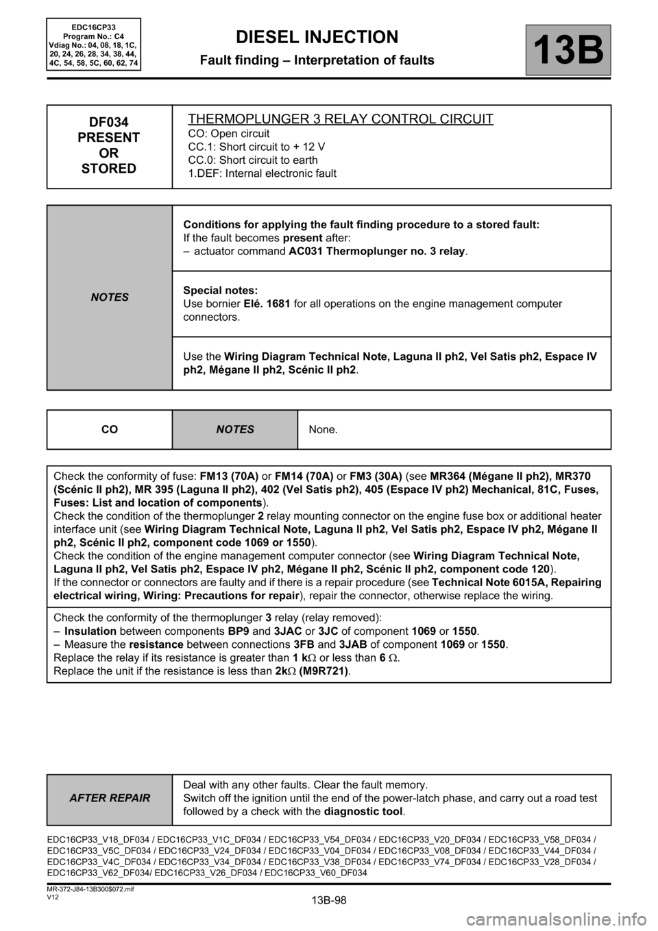
13B-98
AFTER REPAIRDeal with any other faults. Clear the fault memory.
Switch off the ignition until the end of the power-latch phase, and carry out a road test
followed by a check with the diagnostic tool.
V12 MR-372-J84-13B300$072.mif
DIESEL INJECTION
Fault finding – Interpretation of faults13B
EDC16CP33
Program No.: C4
Vdiag No.: 04, 08, 18, 1C,
20, 24, 26, 28, 34, 38, 44,
4C, 54, 58, 5C, 60, 62, 74
DF034
PRESENT
OR
STOREDTHERMOPLUNGER 3 RELAY CONTROL CIRCUITCO: Open circuit
CC.1: Short circuit to + 12 V
CC.0: Short circuit to earth
1.DEF: Internal electronic fault
NOTESConditions for applying the fault finding procedure to a stored fault:
If the fault becomes present after:
– actuator command AC031 Thermoplunger no. 3 relay.
Special notes:
Use bornier Elé. 1681 for all operations on the engine management computer
connectors.
Use the Wiring Diagram Technical Note, Laguna II ph2, Vel Satis ph2, Espace IV
ph2, Mégane II ph2, Scénic II ph2.
CO
NOTESNone.
Check the conformity of fuse: FM13 (70A) or FM14 (70A) or FM3 (30A) (see MR364 (Mégane II ph2), MR370
(Scénic II ph2), MR 395 (Laguna II ph2), 402 (Vel Satis ph2), 405 (Espace IV ph2) Mechanical, 81C, Fuses,
Fuses: List and location of components).
Check the condition of the thermoplunger 2 relay mounting connector on the engine fuse box or additional heater
interface unit (see Wiring Diagram Technical Note, Laguna II ph2, Vel Satis ph2, Espace IV ph2, Mégane II
ph2, Scénic II ph2, component code 1069 or 1550).
Check the condition of the engine management computer connector (see Wiring Diagram Technical Note,
Laguna II ph2, Vel Satis ph2, Espace IV ph2, Mégane II ph2, Scénic II ph2, component code 120).
If the connector or connectors are faulty and if there is a repair procedure (see Technical Note 6015A, Repairing
electrical wiring, Wiring: Precautions for repair), repair the connector, otherwise replace the wiring.
Check the conformity of the thermoplunger 3 relay (relay removed):
–Insulation between components BP9 and 3JAC or 3JC of component 1069 or 1550.
– Measure the resistance between connections 3FB and 3JAB of component 1069 or 1550.
Replace the relay if its resistance is greater than 1 kΩ or less than 6 Ω.
Replace the unit if the resistance is less than 2kΩ (M9R721).
EDC16CP33_V18_DF034 / EDC16CP33_V1C_DF034 / EDC16CP33_V54_DF034 / EDC16CP33_V20_DF034 / EDC16CP33_V58_DF034 /
EDC16CP33_V5C_DF034 / EDC16CP33_V24_DF034 / EDC16CP33_V04_DF034 / EDC16CP33_V08_DF034 / EDC16CP33_V44_DF034 /
EDC16CP33_V4C_DF034 / EDC16CP33_V34_DF034 / EDC16CP33_V38_DF034 / EDC16CP33_V74_DF034 / EDC16CP33_V28_DF034 /
EDC16CP33_V62_DF034/ EDC16CP33_V26_DF034 / EDC16CP33_V60_DF034