differential RENAULT SCENIC 2012 J95 / 3.G Engine And Peripherals EDC16CP33 User Guide
[x] Cancel search | Manufacturer: RENAULT, Model Year: 2012, Model line: SCENIC, Model: RENAULT SCENIC 2012 J95 / 3.GPages: 510, PDF Size: 2.98 MB
Page 198 of 510
13B-198
AFTER REPAIRDeal with any other faults. Clear the fault memory.
Switch off the ignition until the end of the power-latch phase, and carry out a road test
followed by a check with the diagnostic tool.
V12 MR-372-J84-13B300$073.mif
DIESEL INJECTION
Fault finding – Interpretation of faults13B
diff.*: Differential
temp.*: Temperature
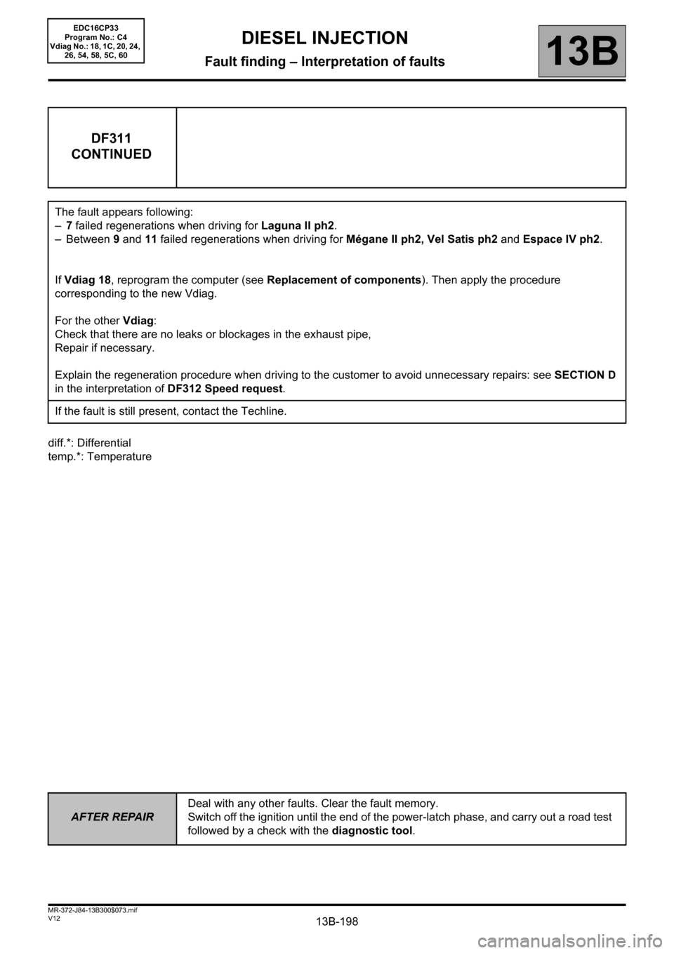
DF311
CONTINUED
The fault appears following:
–7 failed regenerations when driving for Laguna II ph2.
–Between 9 and 11 failed regenerations when driving for Mégane II ph2, Vel Satis ph2 and Espace IV ph2.
If Vdiag 18, reprogram the computer (see Replacement of components). Then apply the procedure
corresponding to the new Vdiag.
For the other Vdiag:
Check that there are no leaks or blockages in the exhaust pipe,
Repair if necessary.
Explain the regeneration procedure when driving to the customer to avoid unnecessary repairs: see SECTION D
in the interpretation of DF312 Speed request.
If the fault is still present, contact the Techline.
EDC16CP33
Program No.: C4
Vdiag No.: 18, 1C, 20, 24,
26, 54, 58, 5C, 60
Page 199 of 510
13B-199
AFTER REPAIRDeal with any other faults. Clear the fault memory.
Switch off the ignition until the end of the power-latch phase, and carry out a road test
followed by a check with the diagnostic tool.
V12 MR-372-J84-13B300$073.mif
DIESEL INJECTION
Fault finding – Interpretation of faults13B
diff.*: Differential
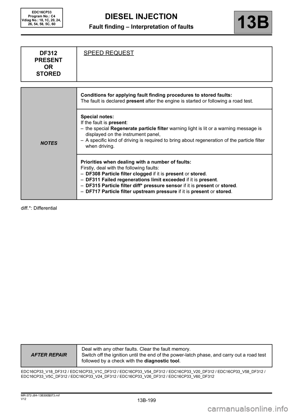
DF312
PRESENT
OR
STOREDSPEED REQUEST
NOTESConditions for applying fault finding procedures to stored faults:
The fault is declared present after the engine is started or following a road test.
Special notes:
If the fault is present:
– the special Regenerate particle filter warning light is lit or a warning message is
displayed on the instrument panel,
– A specific kind of driving is required to bring about regeneration of the particle filter
when driving.
Priorities when dealing with a number of faults:
Firstly, deal with the following faults:
–DF308 Particle filter clogged if it is present or stored.
–DF311 Failed regenerations limit exceeded if it is present.
–DF315 Particle filter diff* pressure sensor if it is present or stored.
–DF717 Particle filter upstream pressure if it is present or stored.
EDC16CP33_V18_DF312 / EDC16CP33_V1C_DF312 / EDC16CP33_V54_DF312 / EDC16CP33_V20_DF312 / EDC16CP33_V58_DF312 /
EDC16CP33_V5C_DF312 / EDC16CP33_V24_DF312 / EDC16CP33_V26_DF312 / EDC16CP33_V60_DF312
EDC16CP33
Program No.: C4
Vdiag No.: 18, 1C, 20, 24,
26, 54, 58, 5C, 60
Page 205 of 510
13B-205
AFTER REPAIRDeal with any other faults. Clear the fault memory.
Switch off the ignition until the end of the power-latch phase, and carry out a road test
followed by a check with the diagnostic tool.
V12 MR-372-J84-13B300$074.mif
DIESEL INJECTION
Fault finding – Interpretation of faults13B
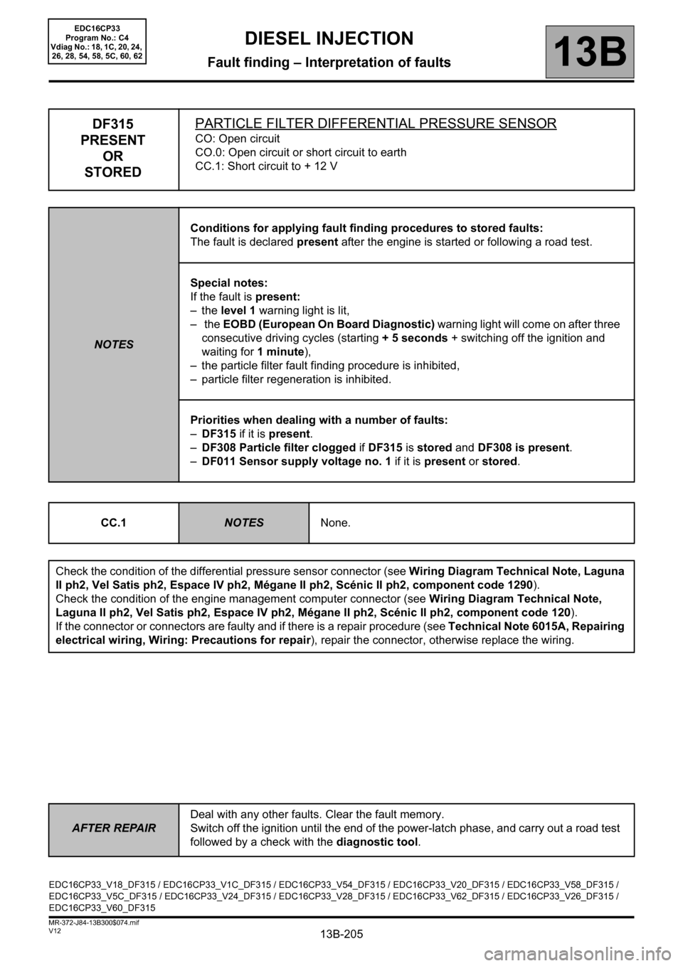
DF315
PRESENT
OR
STOREDPARTICLE FILTER DIFFERENTIAL PRESSURE SENSOR
CO: Open circuit
CO.0: Open circuit or short circuit to earth
CC.1: Short circuit to + 12 V
NOTESConditions for applying fault finding procedures to stored faults:
The fault is declared present after the engine is started or following a road test.
Special notes:
If the fault is present:
–the level 1 warning light is lit,
– the EOBD (European On Board Diagnostic) warning light will come on after three
consecutive driving cycles (starting + 5 seconds + switching off the ignition and
waiting for 1 minute),
– the particle filter fault finding procedure is inhibited,
– particle filter regeneration is inhibited.
Priorities when dealing with a number of faults:
–DF315 if it is present.
–DF308 Particle filter clogged if DF315 is stored and DF308 is present.
–DF011 Sensor supply voltage no. 1 if it is present or stored.
CC.1
NOTESNone.
Check the condition of the differential pressure sensor connector (see Wiring Diagram Technical Note, Laguna
II ph2, Vel Satis ph2, Espace IV ph2, Mégane II ph2, Scénic II ph2, component code 1290).
Check the condition of the engine management computer connector (see Wiring Diagram Technical Note,
Laguna II ph2, Vel Satis ph2, Espace IV ph2, Mégane II ph2, Scénic II ph2, component code 120).
If the connector or connectors are faulty and if there is a repair procedure (see Technical Note 6015A, Repairing
electrical wiring, Wiring: Precautions for repair), repair the connector, otherwise replace the wiring.
EDC16CP33_V18_DF315 / EDC16CP33_V1C_DF315 / EDC16CP33_V54_DF315 / EDC16CP33_V20_DF315 / EDC16CP33_V58_DF315 /
EDC16CP33_V5C_DF315 / EDC16CP33_V24_DF315 / EDC16CP33_V28_DF315 / EDC16CP33_V62_DF315 / EDC16CP33_V26_DF315 /
EDC16CP33_V60_DF315
EDC16CP33
Program No.: C4
Vdiag No.: 18, 1C, 20, 24,
26, 28, 54, 58, 5C, 60, 62
Page 206 of 510
13B-206
AFTER REPAIRDeal with any other faults. Clear the fault memory.
Switch off the ignition until the end of the power-latch phase, and carry out a road test
followed by a check with the diagnostic tool.
V12 MR-372-J84-13B300$074.mif
DIESEL INJECTION
Fault finding – Interpretation of faults13B
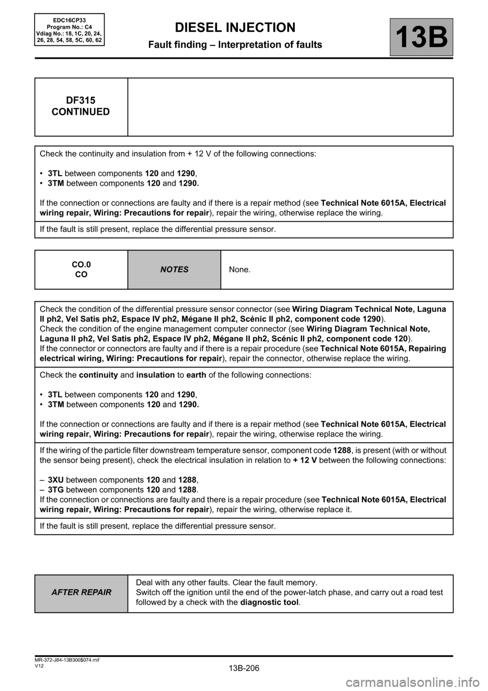
DF315
CONTINUED
Check the continuity and insulation from + 12 V of the following connections:
•3TL between components 120 and 1290,
•3TM between components 120 and 1290.
If the connection or connections are faulty and if there is a repair method (see Technical Note 6015A, Electrical
wiring repair, Wiring: Precautions for repair), repair the wiring, otherwise replace the wiring.
If the fault is still present, replace the differential pressure sensor.
CO.0
CO
NOTESNone.
Check the condition of the differential pressure sensor connector (see Wiring Diagram Technical Note, Laguna
II ph2, Vel Satis ph2, Espace IV ph2, Mégane II ph2, Scénic II ph2, component code 1290).
Check the condition of the engine management computer connector (see Wiring Diagram Technical Note,
Laguna II ph2, Vel Satis ph2, Espace IV ph2, Mégane II ph2, Scénic II ph2, component code 120).
If the connector or connectors are faulty and if there is a repair procedure (see Technical Note 6015A, Repairing
electrical wiring, Wiring: Precautions for repair), repair the connector, otherwise replace the wiring.
Check the continuity and insulation to earth of the following connections:
•3TL between components 120 and 1290,
•3TM between components 120 and 1290.
If the connection or connections are faulty and if there is a repair method (see Technical Note 6015A, Electrical
wiring repair, Wiring: Precautions for repair), repair the wiring, otherwise replace the wiring.
If the wiring of the particle filter downstream temperature sensor, component code 1288, is present (with or without
the sensor being present), check the electrical insulation in relation to + 12 V between the following connections:
–3XU between components 120 and 1288,
–3TG between components 120 and 1288.
If the connection or connections are faulty and there is a repair procedure (see Technical Note 6015A, Electrical
wiring repair, Wiring: Precautions for repair), repair the wiring, otherwise replace it.
If the fault is still present, replace the differential pressure sensor.
EDC16CP33
Program No.: C4
Vdiag No.: 18, 1C, 20, 24,
26, 28, 54, 58, 5C, 60, 62
Page 234 of 510
13B-234
AFTER REPAIRDeal with any other faults. Clear the fault memory.
Switch off the ignition until the end of the power-latch phase, and carry out a road test
followed by a check with the diagnostic tool.
V12 MR-372-J84-13B300$074.mif
DIESEL INJECTION
Fault finding – Interpretation of faults13B
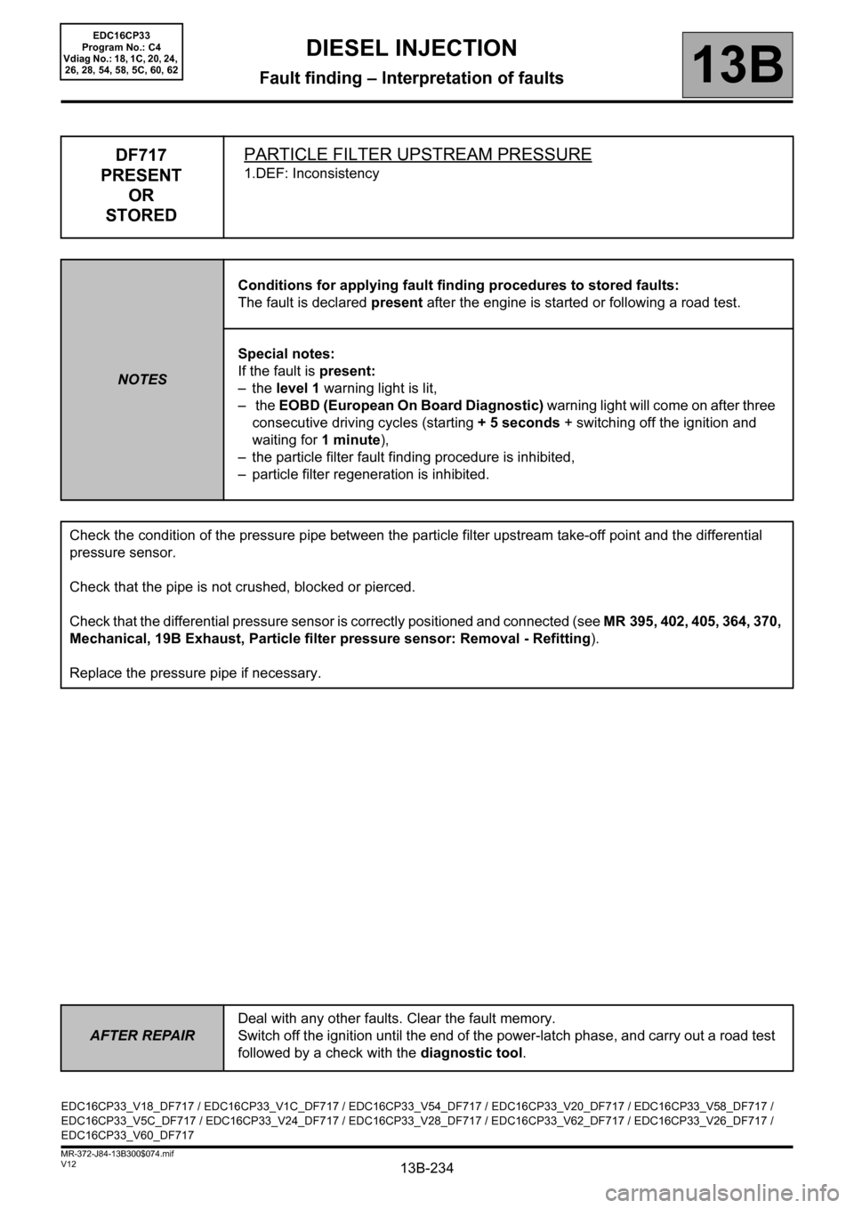
DF717
PRESENT
OR
STOREDPARTICLE FILTER UPSTREAM PRESSURE
1.DEF: Inconsistency
NOTESConditions for applying fault finding procedures to stored faults:
The fault is declared present after the engine is started or following a road test.
Special notes:
If the fault is present:
–the level 1 warning light is lit,
– the EOBD (European On Board Diagnostic) warning light will come on after three
consecutive driving cycles (starting + 5 seconds + switching off the ignition and
waiting for 1 minute),
– the particle filter fault finding procedure is inhibited,
– particle filter regeneration is inhibited.
Check the condition of the pressure pipe between the particle filter upstream take-off point and the differential
pressure sensor.
Check that the pipe is not crushed, blocked or pierced.
Check that the differential pressure sensor is correctly positioned and connected (see MR 395, 402, 405, 364, 370,
Mechanical, 19B Exhaust, Particle filter pressure sensor: Removal - Refitting).
Replace the pressure pipe if necessary.
EDC16CP33_V18_DF717 / EDC16CP33_V1C_DF717 / EDC16CP33_V54_DF717 / EDC16CP33_V20_DF717 / EDC16CP33_V58_DF717 /
EDC16CP33_V5C_DF717 / EDC16CP33_V24_DF717 / EDC16CP33_V28_DF717 / EDC16CP33_V62_DF717 / EDC16CP33_V26_DF717 /
EDC16CP33_V60_DF717
EDC16CP33
Program No.: C4
Vdiag No.: 18, 1C, 20, 24,
26, 28, 54, 58, 5C, 60, 62
Page 327 of 510
13B-327V12 MR-372-J84-13B300$110.mif
DIESEL INJECTION
Fault finding – Parameter summary table13B
EDC16CP33
Program No.: C4
VDiag No.: 04, 08, 18, 1C,
20, 24, 26, 28, 34, 38, 44,
4C, 54, 58, 5C, 60, 62, 74
repl*: replacement,
diff.*: differential,
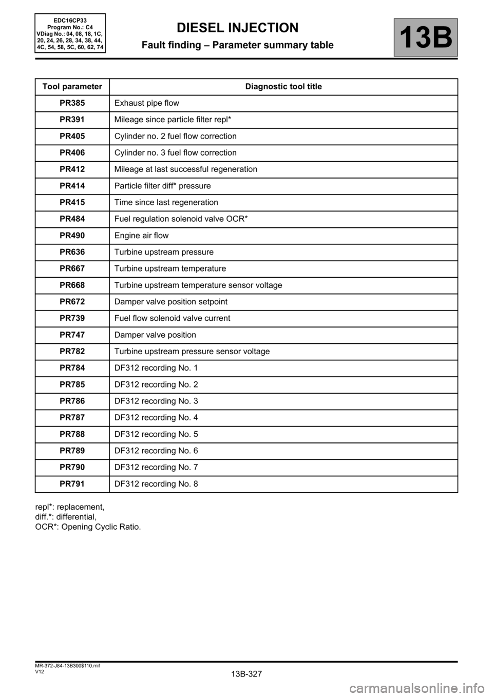
OCR*: Opening Cyclic Ratio.Tool parameter Diagnostic tool title
PR385Exhaust pipe flow
PR391Mileage since particle filter repl*
PR405Cylinder no. 2 fuel flow correction
PR406Cylinder no. 3 fuel flow correction
PR412Mileage at last successful regeneration
PR414Particle filter diff* pressure
PR415Time since last regeneration
PR484Fuel regulation solenoid valve OCR*
PR490Engine air flow
PR636Turbine upstream pressure
PR667Turbine upstream temperature
PR668Turbine upstream temperature sensor voltage
PR672Damper valve position setpoint
PR739Fuel flow solenoid valve current
PR747Damper valve position
PR782Turbine upstream pressure sensor voltage
PR784DF312 recording No. 1
PR785DF312 recording No. 2
PR786DF312 recording No. 3
PR787DF312 recording No. 4
PR788DF312 recording No. 5
PR789DF312 recording No. 6
PR790DF312 recording No. 7
PR791DF312 recording No. 8
Page 388 of 510
13B-388V12 MR-372-J84-13B300$122.mif
DIESEL INJECTION
Fault finding – Interpretation of parameters13B
diff.*: differential
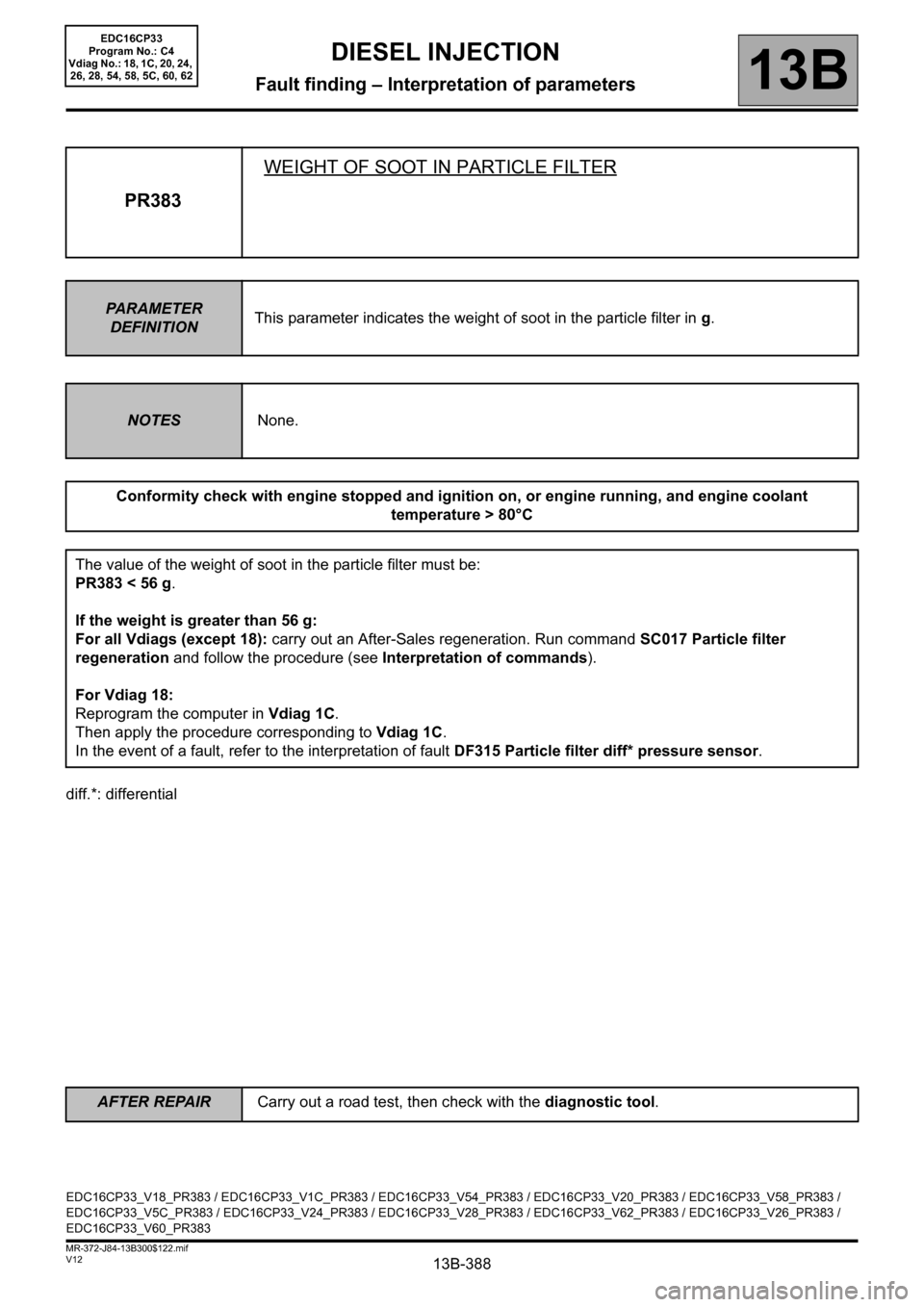
PR383WEIGHT OF SOOT IN PARTICLE FILTER
PARAMETER
DEFINITIONThis parameter indicates the weight of soot in the particle filter in g.
NOTESNone.
Conformity check with engine stopped and ignition on, or engine running, and engine coolant
temperature > 80°C
The value of the weight of soot in the particle filter must be:
PR383 < 56 g.
If the weight is greater than 56 g:
For all Vdiags (except 18): carry out an After-Sales regeneration. Run command SC017 Particle filter
regeneration and follow the procedure (see Interpretation of commands).
For Vdiag 18:
Reprogram the computer in Vdiag 1C.
Then apply the procedure corresponding to Vdiag 1C.
In the event of a fault, refer to the interpretation of fault DF315 Particle filter diff* pressure sensor.
EDC16CP33_V18_PR383 / EDC16CP33_V1C_PR383 / EDC16CP33_V54_PR383 / EDC16CP33_V20_PR383 / EDC16CP33_V58_PR383 /
EDC16CP33_V5C_PR383 / EDC16CP33_V24_PR383 / EDC16CP33_V28_PR383 / EDC16CP33_V62_PR383 / EDC16CP33_V26_PR383 /
EDC16CP33_V60_PR383
EDC16CP33
Program No.: C4
Vdiag No.: 18, 1C, 20, 24,
26, 28, 54, 58, 5C, 60, 62
AFTER REPAIRCarry out a road test, then check with the diagnostic tool.
Page 394 of 510
13B-394V12 MR-372-J84-13B300$122.mif
DIESEL INJECTION
Fault finding – Interpretation of parameters13B
diff.*: differential
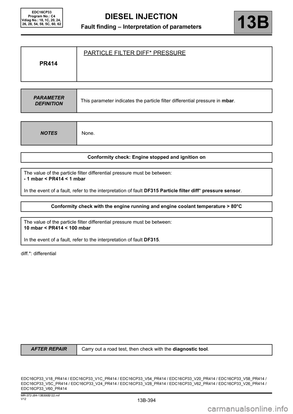
PR414PARTICLE FILTER DIFF* PRESSURE
PARAMETER
DEFINITIONThis parameter indicates the particle filter differential pressure in mbar.
NOTESNone.
Conformity check: Engine stopped and ignition on
The value of the particle filter differential pressure must be between:
- 1 mbar < PR414 < 1 mbar
In the event of a fault, refer to the interpretation of fault DF315 Particle filter diff* pressure sensor.
Conformity check with the engine running and engine coolant temperature > 80°C
The value of the particle filter differential pressure must be between:
10 mbar < PR414 < 100 mbar
In the event of a fault, refer to the interpretation of fault DF315.
EDC16CP33_V18_PR414 / EDC16CP33_V1C_PR414 / EDC16CP33_V54_PR414 / EDC16CP33_V20_PR414 / EDC16CP33_V58_PR414 /
EDC16CP33_V5C_PR414 / EDC16CP33_V24_PR414 / EDC16CP33_V28_PR414 / EDC16CP33_V62_PR414 / EDC16CP33_V26_PR414 /
EDC16CP33_V60_PR414
EDC16CP33
Program No.: C4
Vdiag No.: 18, 1C, 20, 24,
26, 28, 54, 58, 5C, 60, 62
AFTER REPAIRCarry out a road test, then check with the diagnostic tool.
Page 478 of 510
13B-478
AFTER REPAIRCarry out a road test, then check with the diagnostic tool.
V12 MR-372-J84-13B300$170.mif
DIESEL INJECTION
Fault finding – Fault Finding Chart13B
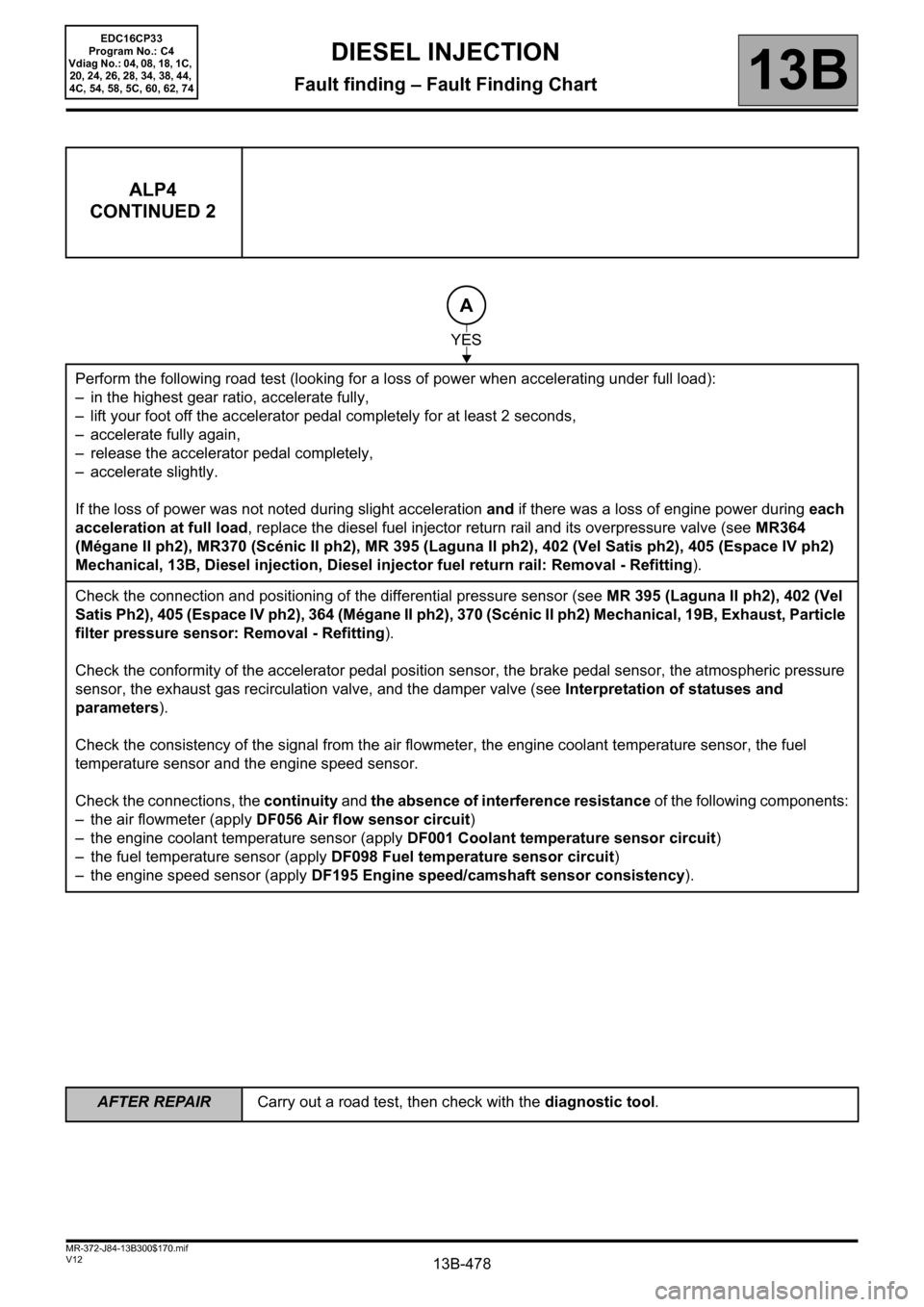
ALP4
CONTINUED 2
Perform the following road test (looking for a loss of power when accelerating under full load):
– in the highest gear ratio, accelerate fully,
– lift your foot off the accelerator pedal completely for at least 2 seconds,
– accelerate fully again,
– release the accelerator pedal completely,
– accelerate slightly.
If the loss of power was not noted during slight acceleration and if there was a loss of engine power during each
acceleration at full load, replace the diesel fuel injector return rail and its overpressure valve (see MR364
(Mégane II ph2), MR370 (Scénic II ph2), MR 395 (Laguna II ph2), 402 (Vel Satis ph2), 405 (Espace IV ph2)
Mechanical, 13B, Diesel injection, Diesel injector fuel return rail: Removal - Refitting).
Check the connection and positioning of the differential pressure sensor (see MR 395 (Laguna II ph2), 402 (Vel
Satis Ph2), 405 (Espace IV ph2), 364 (Mégane II ph2), 370 (Scénic II ph2) Mechanical, 19B, Exhaust, Particle
filter pressure sensor: Removal - Refitting).
Check the conformity of the accelerator pedal position sensor, the brake pedal sensor, the atmospheric pressure
sensor, the exhaust gas recirculation valve, and the damper valve (see Interpretation of statuses and
parameters).
Check the consistency of the signal from the air flowmeter, the engine coolant temperature sensor, the fuel
temperature sensor and the engine speed sensor.
Check the connections, the continuity and the absence of interference resistance of the following components:
– the air flowmeter (apply DF056 Air flow sensor circuit)
– the engine coolant temperature sensor (apply DF001 Coolant temperature sensor circuit)
– the fuel temperature sensor (apply DF098 Fuel temperature sensor circuit)
– the engine speed sensor (apply DF195 Engine speed/camshaft sensor consistency).
A
YES
EDC16CP33
Program No.: C4
Vdiag No.: 04, 08, 18, 1C,
20, 24, 26, 28, 34, 38, 44,
4C, 54, 58, 5C, 60, 62, 74
Page 490 of 510
13B-490
AFTER REPAIRCarry out a road test, then check with the diagnostic tool.
V12 MR-372-J84-13B300$170.mif
DIESEL INJECTION
Fault finding – Fault Finding Chart13B
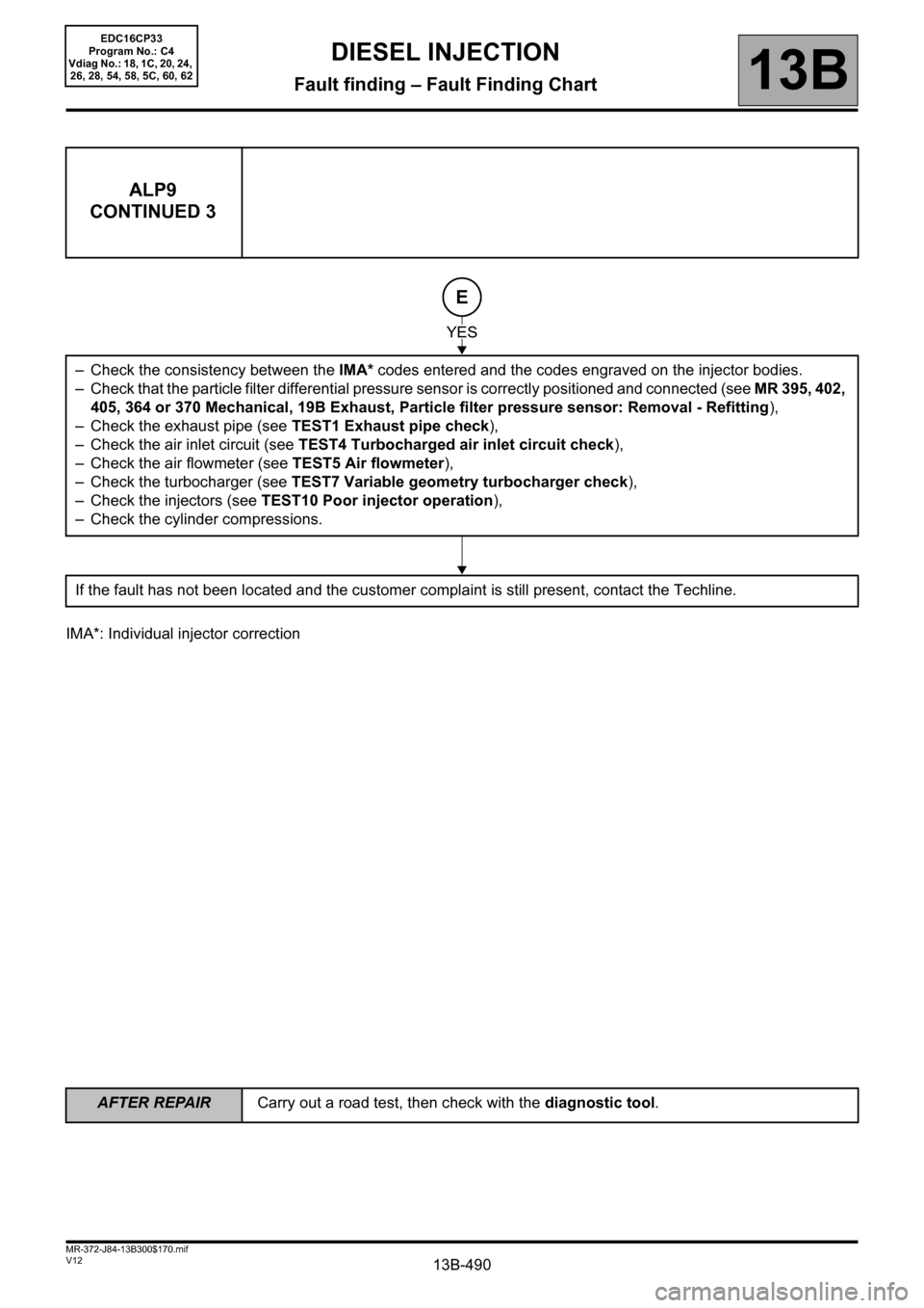
IMA*: Individual injector correction
ALP9
CONTINUED 3
– Check the consistency between the IMA* codes entered and the codes engraved on the injector bodies.
– Check that the particle filter differential pressure sensor is correctly positioned and connected (see MR 395, 402,
405, 364 or 370 Mechanical, 19B Exhaust, Particle filter pressure sensor: Removal - Refitting),
– Check the exhaust pipe (see TEST1 Exhaust pipe check),
– Check the air inlet circuit (see TEST4 Turbocharged air inlet circuit check),
– Check the air flowmeter (see TEST5 Air flowmeter),
– Check the turbocharger (see TEST7 Variable geometry turbocharger check),
– Check the injectors (see TEST10 Poor injector operation),
– Check the cylinder compressions.
If the fault has not been located and the customer complaint is still present, contact the Techline.
YES
E
EDC16CP33
Program No.: C4
Vdiag No.: 18, 1C, 20, 24,
26, 28, 54, 58, 5C, 60, 62