sensor RENAULT SCENIC 2012 J95 / 3.G Engine And Peripherals EDC16CP33 Workshop Manual
[x] Cancel search | Manufacturer: RENAULT, Model Year: 2012, Model line: SCENIC, Model: RENAULT SCENIC 2012 J95 / 3.GPages: 510, PDF Size: 2.98 MB
Page 11 of 510
13B-11V12 MR-372-J84-13B300$030.mif
13B
EDC16CP33
Program No.: C4
Vdiag No.: 04, 08, 18, 1C,
20, 24, 26, 28, 34, 38, 44,
4C, 54, 58, 5C, 60, 62, 74
System outline
The high pressure injection system is designed to deliver a precise quantity of diesel fuel to the engine at a set
moment.
It is fitted with a BOSCH computer, type EDC16CP33.
The system comprises:
– a priming bulb,
– a diesel filter,
– a high pressure pump,
– a fuel pressure regulator (or actuator) on the high pressure pump (MPROP),
– a fuel pressure regulator (or actuator) mounted on the injector rail (DRV),
– an injector rail,
– a fuel pressure sensor,
– four piezoelectric injectors,
– a diesel temperature sensor,
– a coolant temperature sensor,
– an upstream air temperature sensor,
– a cylinder reference sensor,
– an engine speed sensor,
– a turbocharger pressure sensor,
– an exhaust gas recirculation valve,
– a recycled gas cooling solenoid valve,
– an accelerator pedal potentiometer,
– an atmospheric pressure sensor integrated into the injection computer,
– a flow sensor,
– a turbocharging limiter solenoid valve,
– a damper valve,
– a particle filter,
– a turbo upstream temperature sensor,
– a turbo upstream pressure sensor,
– a particle filter differential pressure sensor,
– a particle filter upstream temperature sensor,
– a particle filter downstream temperature sensor,
– an electric coolant pump (turbocharger),
– four thermoplungers.
The common rail direct high pressure injection system works sequentially (based on the petrol engine
multipoint injection).
This system uses piezoelectric injectors which enable a more precise injection since opening and closing times
are shorter compared to conventional solenoid injectors.
This injection system reduces operating noise, reduces the volume of pollutant gases and particles and produces
high engine torque at low engine speeds thanks to a pre-injection procedure.
The high pressure pump generates the high pressure and transmits it to the injector rail. The actuator located on
the pump controls the quantity of diesel supplied, according to the demand determined by the computer.
The rail supplies each injector through a steel pipe. The actuator located on the injector rail controls the pressure
of diesel fuel in the rail according to the demand determined by the computer.
DIESEL INJECTION
Fault finding – System operation
Page 12 of 510
13B-12V12 MR-372-J84-13B300$030.mif
DIESEL INJECTION
Fault finding – System operation13B
EDC16CP33
Program No.: C4
Vdiag No.: 04, 08, 18, 1C,
20, 24, 26, 28, 34, 38, 44,
4C, 54, 58, 5C, 60, 62, 74
a. The computer:
Determines the injection pressure value necessary for the correct operation of the engine; the pressure can reach
1600 bar in the rail and it must be constantly regulated.
Checks that the pressure value is correct by analysing the value transmitted by the pressure sensor located on
the rail.
Determines the injection duration required to deliver the right quantity of diesel fuel and the moment when injection
should start. Controls each injector electrically and individually after determining these two values.
The quantity of fuel injected is determined by:
– Engine speed (Crankshaft + Cam for synchronisation).
– Accelerator pedal.
– Turbocharging pressure.
– Coolant temperature,
– Inlet air temperature.
–Air flow
– Pressure in the rail.
– Vehicle speed.
The computer manages:
– idling regulation,
– exhaust gas flow reinjection to the inlet,
– fuel supply check (advance, flow and rail pressure),
– the fan assembly control,
– the air conditioning (cold loop function),
– cruise control/speed limiter function,
– pre-post heating control,
– indicator lights control via the multiplex network,
– the operation of the catalysed particle filter,
– turbocharging pressure.
The high pressure pump is supplied at low pressure by an integrated low pressure pump (transfer pump).
It supplies the rail, the pressure in which is regulated by:
–the pressure regulator on the rail (DRV) for starting phases, starting the engine when cold (increase in
temperature to heat the diesel circuit) and when throttling-off,
–the pressure regulator on the pump (MPROP) for all other phases (90% of cases).
As natural leaks in piezoelectric injectors are very low, opening the pressure regulator (DRV) is the only quick
method of dumping the rail pressure and it prevents overpressure when injection is restarted.
The pressure regulator on the pump (MPROP) enables the high pressure pump to supply just the exact quantity
of diesel fuel required to maintain the rail pressure. This component minimises the heat generated and improves
engine output.
Note:
Each piezoelectric injector is connected to the return rail. The injector return rail is kept pressurised by a
mechanical valve at the end of the return rail with a 10 bar calibration (by comparison, solenoid injectors used to
return directly into the common fuel return circuit). This feature is linked to the operation of piezoelectric injectors.
Page 13 of 510
13B-13V12 MR-372-J84-13B300$030.mif
DIESEL INJECTION
Fault finding – System operation13B
EDC16CP33
Program No.: C4
Vdiag No.: 04, 08, 18, 1C,
20, 24, 26, 28, 34, 38, 44,
4C, 54, 58, 5C, 60, 62, 74
Fuel surplus from the pump, injector return rail or rail is collected in a low pressure "octopus manifold" and is then
sent to the fuel filter, providing that the fuel is cold (recirculation), and then to the tank.
The system can inject diesel fuel into the engine at a pressure of up to 1600 bar. Before each operation, check that
the injector rail is depressurised and that the fuel temperature is not too high.
You must respect the cleanliness guidelines and safety advice specified in this document for any work on the high
pressure injection system.
Removal of the internal parts of the pump and injectors is prohibited. Only the fuel pressure regulator (or actuator)
on the high pressure pump (MPROP), the fuel pressure regulator (or actuator) on the injector rail (DRV) or the diesel
temperature sensor can be replaced.
For safety reasons, it is strictly prohibited to undo a high pressure pipe union when the engine is running.
It is not possible to remove the pressure sensor from the fuel rail because this may cause circuit contamination
faults. If the pressure sensor fails, replace the pressure sensor, the rail and the high pressure pipes.
Some vehicles have a presence sensor mounted in the filter for detecting water in the diesel. If there is water in
the diesel fuel, the orange "Injection and pre-post heating" warning light will come on.
Supplying + 12 V directly to any component in the system is prohibited.
Ultrasonic decoking and cleaning are prohibited.
Never start the engine unless the battery is connected correctly.
Disconnect the injection computer when carrying out any welding work on the vehicle.
b. The connections between the vehicle's various computers are multiplexed.
The electronic system fitted in this vehicle is multiplexed.
This enables dialogue between the various vehicle computers. As a result:
– the fault warning lights on the instrument panel are lit by the multiplex network,
– vehicle faults are displayed by the multiplex network,
– the vehicle speed sensor on the gearbox is not needed.
The vehicle speed signal on the instrument panel is sent by the ABS computer via the multiplex network. The vehicle
speed signal is mainly used by the injection computer, the airbag computer and the automatic transmission
computer (if the vehicle is fitted with this).WARNING:
The engine must not operate with:
– Diesel fuel containing more than 10% diester,
– petrol, even in tiny quantities.
Note:
For the M9R 724 (Vdiag 5C and 58):
The engine is limited to 3000 rpm if the vehicle is stationary or if the vehicle speed is less than 4 mph (7 km/h)
and if the engine is warm.
Page 16 of 510
13B-16V12 MR-372-J84-13B300$030.mif
DIESEL INJECTION
Fault finding – System operation13B
EDC16CP33
Program No.: C4
Vdiag No.: 04, 08, 18, 1C,
20, 24, 26, 28, 34, 38, 44,
4C, 54, 58, 5C, 60, 62, 74
III - Management of the damper valve
The damper valve is now responsible for two functions:
– Damping: when the engine is switched off, the flap closes in order to block the passage of air towards the cylinders.
The aim of this is to stop the engine as quickly as possible and to reduce instabilities when the engine is switched
off.
– "Valving" function depending on the engine operation: the damper valve closes by a few % to create a "venturi"
effect at the EGR valve passage section.
The aim of this is to accelerate the air flow of EGR gases and to reduce the emission of pollutants.
IV - Exhaust gas recirculation management
The EGR (Exhaust Gas Recirculation) system involves removing exhaust gases and reintroducing them into the
inlet.
This system plays a major role in reducing diesel engine emissions. The EGR system is cooled by a gas - water
exchanger, as on most Euro IV engines. This cooler has a dual position bypass valve, which allows the gas to be
cooled or not depending on the emission control requirements. The bypass circuit is inside the cooler (not visible
from the outside). The valve control rod is visible from the outside.
The exhaust gases are collected in the exhaust manifold (before the turbocharger), then directed to the EGR cooler
and the EGR valve. The EGR valve connects the air circuit between the damper valve and the inlet manifold; the
EGR valve is positioned next to the damper valve.
The EGR valve is activated every time the engine stops by performing 10opening/closing cycles. This programming
activates the EGR valve in order to prevent it from clogging. The program is no longer active if there are any system
faults.
The EGR system does not operate below 5°C (air flowmeter temperature).
– The controlled EGR cooler bypass
The EGR cooler bypass is controlled by an all-or-nothing solenoid valve, connected on one side to the vacuum
pump, and on the other side to the bypass control diaphragm. It is actuated according to the coolant temperature
and the engine operating status. Gases flow into the EGR section of the cooler unless the engine is cold, in which
case they flow through the bypass valve. There is also a regular actuation function for the bypass valve to prevent it
from clogging.
– EGR valve
The EGR valve is supplied by direct current and connected to a potentiometer copying the position of the valve.
The opening of the valve is actuated (H bridge) by a positive command 0 to 100%.
The valve is controlled using a double regulation loop.
The first loop (fastest) is a position loop. It brings the valve to the desired position by a loop connection using the
signal from the position sensor.
The second loop is slower and is an air flow loop. At a given operating point, the air flow setpoint is attained by
adjusting the quantity of exhaust gas flowing through the EGR valve and the flow of fresh air passing through the
damper valve. At a total constant flow, the more exhaust gas recirculation, the less fresh air there is and vice versa.
The air flow is measured by the flowmeter and the setpoint is attained using both the EGR valve position setpoint
and the damper valve position setpoint.
Page 17 of 510
13B-17V12 MR-372-J84-13B300$030.mif
DIESEL INJECTION
Fault finding – System operation13B
EDC16CP33
Program No.: C4
Vdiag No.: 04, 08, 18, 1C,
20, 24, 26, 28, 34, 38, 44,
4C, 54, 58, 5C, 60, 62, 74
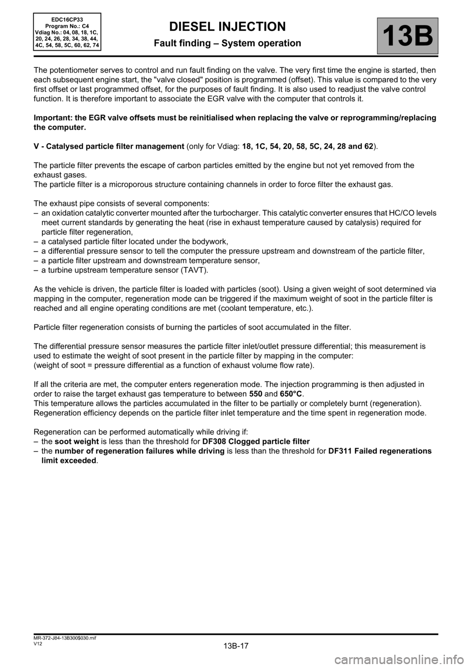
The potentiometer serves to control and run fault finding on the valve. The very first time the engine is started, then
each subsequent engine start, the "valve closed" position is programmed (offset). This value is compared to the very
first offset or last programmed offset, for the purposes of fault finding. It is also used to readjust the valve control
function. It is therefore important to associate the EGR valve with the computer that controls it.
Important: the EGR valve offsets must be reinitialised when replacing the valve or reprogramming/replacing
the computer.
V - Catalysed particle filter management (only for Vdiag: 18, 1C, 54, 20, 58, 5C, 24, 28 and 62).
The particle filter prevents the escape of carbon particles emitted by the engine but not yet removed from the
exhaust gases.
The particle filter is a microporous structure containing channels in order to force filter the exhaust gas.
The exhaust pipe consists of several components:
– an oxidation catalytic converter mounted after the turbocharger. This catalytic converter ensures that HC/CO levels
meet current standards by generating the heat (rise in exhaust temperature caused by catalysis) required for
particle filter regeneration,
– a catalysed particle filter located under the bodywork,
– a differential pressure sensor to tell the computer the pressure upstream and downstream of the particle filter,
– a particle filter upstream and downstream temperature sensor,
– a turbine upstream temperature sensor (TAVT).
As the vehicle is driven, the particle filter is loaded with particles (soot). Using a given weight of soot determined via
mapping in the computer, regeneration mode can be triggered if the maximum weight of soot in the particle filter is
reached and all engine operating conditions are met (coolant temperature, etc.).
Particle filter regeneration consists of burning the particles of soot accumulated in the filter.
The differential pressure sensor measures the particle filter inlet/outlet pressure differential; this measurement is
used to estimate the weight of soot present in the particle filter by mapping in the computer:
(weight of soot = pressure differential as a function of exhaust volume flow rate).
If all the criteria are met, the computer enters regeneration mode. The injection programming is then adjusted in
order to raise the target exhaust gas temperature to between 550 and 650°C.
This temperature allows the particles accumulated in the filter to be partially or completely burnt (regeneration).
Regeneration efficiency depends on the particle filter inlet temperature and the time spent in regeneration mode.
Regeneration can be performed automatically while driving if:
–the soot weight is less than the threshold for DF308 Clogged particle filter
–the number of regeneration failures while driving is less than the threshold for DF311 Failed regenerations
limit exceeded.
Page 20 of 510
13B-20V12 MR-372-J84-13B300$030.mif
DIESEL INJECTION
Fault finding – System operation13B
EDC16CP33
Program No.: C4
Vdiag No.: 04, 08, 18, 1C,
20, 24, 26, 28, 34, 38, 44,
4C, 54, 58, 5C, 60, 62, 74
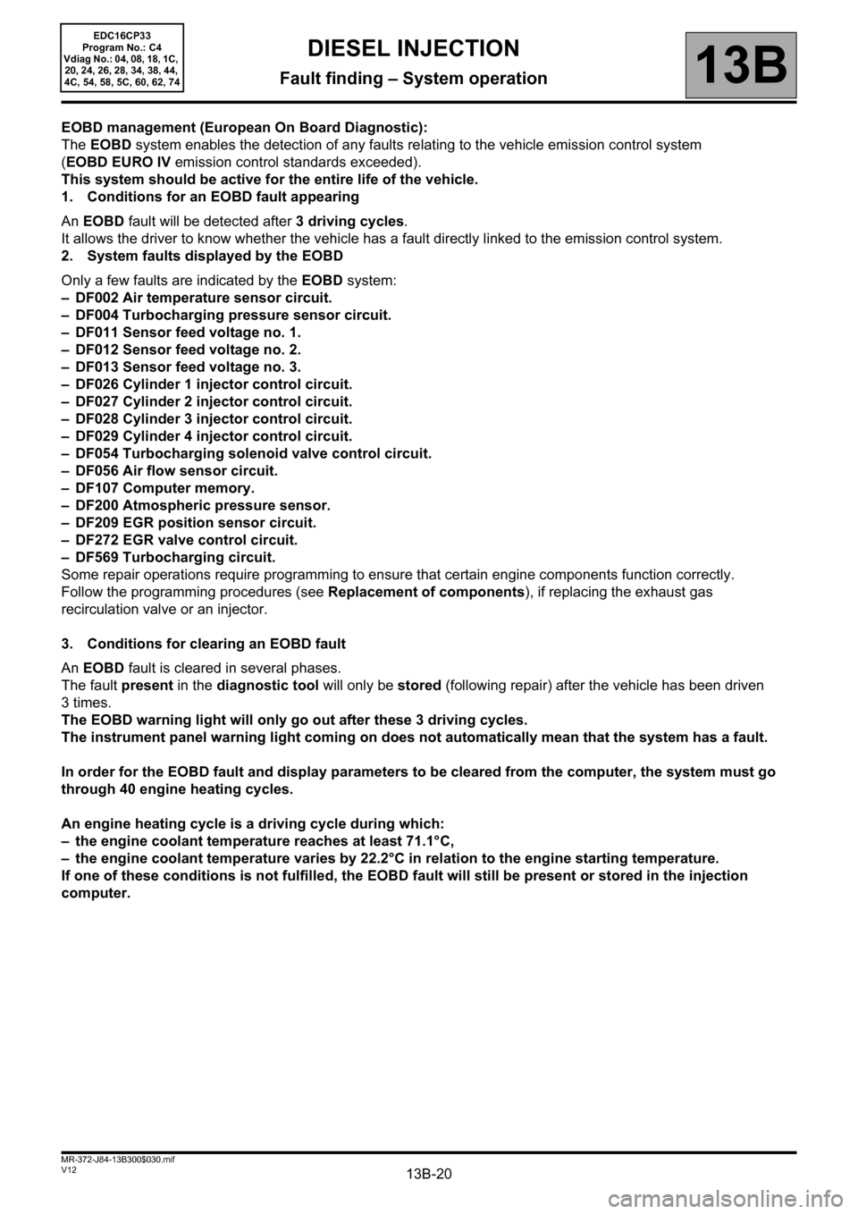
EOBD management (European On Board Diagnostic):
The EOBD system enables the detection of any faults relating to the vehicle emission control system
(EOBD EURO IV emission control standards exceeded).
This system should be active for the entire life of the vehicle.
1. Conditions for an EOBD fault appearing
An EOBD fault will be detected after 3 driving cycles.
It allows the driver to know whether the vehicle has a fault directly linked to the emission control system.
2. System faults displayed by the EOBD
Only a few faults are indicated by the EOBD system:
– DF002 Air temperature sensor circuit.
– DF004 Turbocharging pressure sensor circuit.
– DF011 Sensor feed voltage no. 1.
– DF012 Sensor feed voltage no. 2.
– DF013 Sensor feed voltage no. 3.
– DF026 Cylinder 1 injector control circuit.
– DF027 Cylinder 2 injector control circuit.
– DF028 Cylinder 3 injector control circuit.
– DF029 Cylinder 4 injector control circuit.
– DF054 Turbocharging solenoid valve control circuit.
– DF056 Air flow sensor circuit.
– DF107 Computer memory.
– DF200 Atmospheric pressure sensor.
– DF209 EGR position sensor circuit.
– DF272 EGR valve control circuit.
– DF569 Turbocharging circuit.
Some repair operations require programming to ensure that certain engine components function correctly.
Follow the programming procedures (see Replacement of components), if replacing the exhaust gas
recirculation valve or an injector.
3. Conditions for clearing an EOBD fault
An EOBD fault is cleared in several phases.
The fault present in the diagnostic tool will only be stored (following repair) after the vehicle has been driven
3times.
The EOBD warning light will only go out after these 3 driving cycles.
The instrument panel warning light coming on does not automatically mean that the system has a fault.
In order for the EOBD fault and display parameters to be cleared from the computer, the system must go
through 40 engine heating cycles.
An engine heating cycle is a driving cycle during which:
– the engine coolant temperature reaches at least 71.1°C,
– the engine coolant temperature varies by 22.2°C in relation to the engine starting temperature.
If one of these conditions is not fulfilled, the EOBD fault will still be present or stored in the injection
computer.
Page 21 of 510
13B-21V12 MR-372-J84-13B300$040.mif
13B
EDC16CP33
Program No.: C4
Vdiag No.: 04, 08, 18, 1C,
20, 24, 26, 28, 34, 38, 44,
4C, 54, 58, 5C, 60, 62, 74
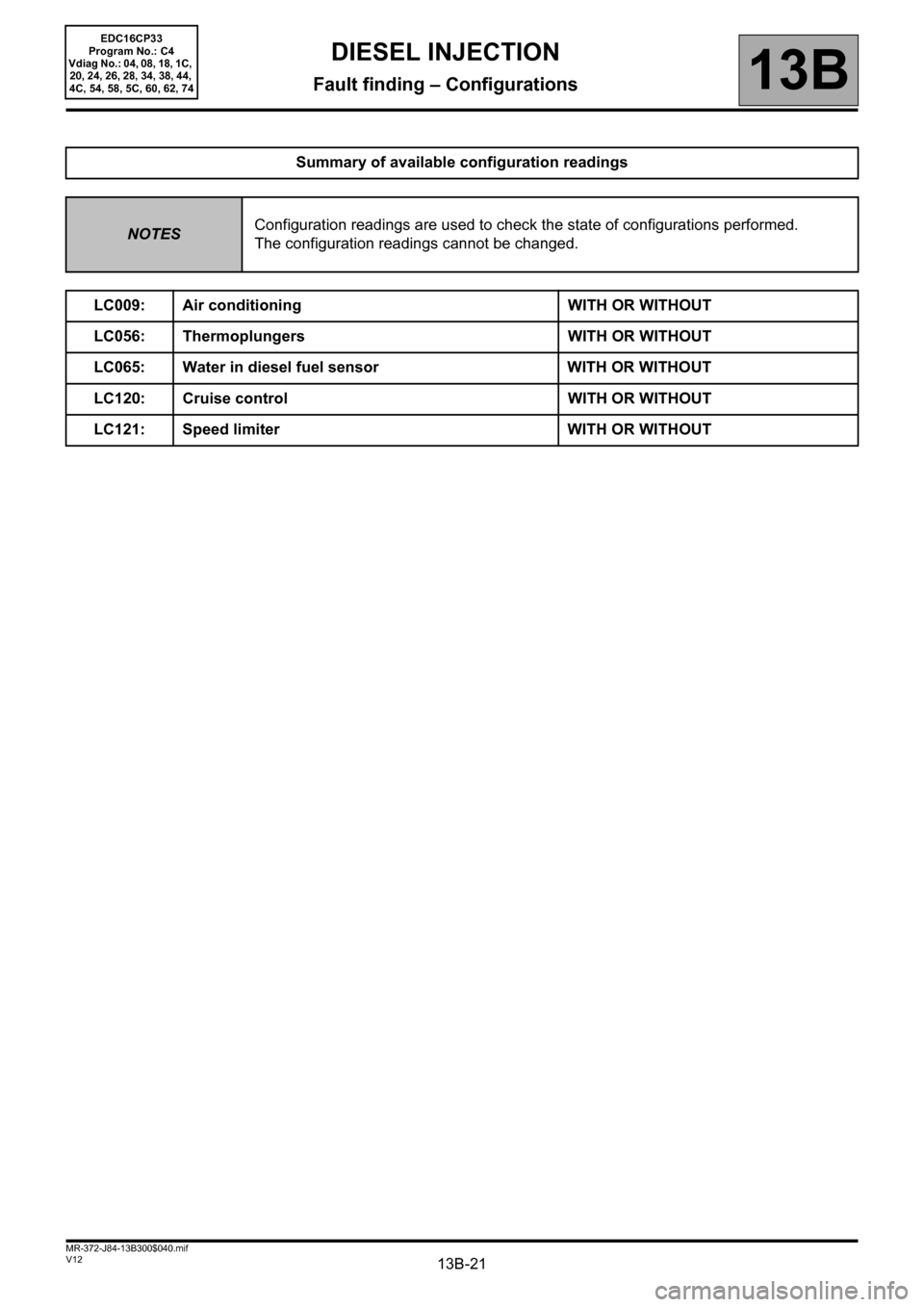
Summary of available configuration readings
NOTESConfiguration readings are used to check the state of configurations performed.
The configuration readings cannot be changed.
LC009: Air conditioning WITH OR WITHOUT
LC056: Thermoplungers WITH OR WITHOUT
LC065: Water in diesel fuel sensor WITH OR WITHOUT
LC120: Cruise control WITH OR WITHOUT
LC121: Speed limiter WITH OR WITHOUT
DIESEL INJECTION
Fault finding – Configurations
Page 28 of 510
13B-28V12 MR-372-J84-13B300$060.mif
13B
EDC16CP33
Program No.: C4
Vdiag No.: 04, 08, 18, 1C,
20, 24, 26, 28, 34, 38, 44,
4C, 54, 58, 5C, 60, 62, 74
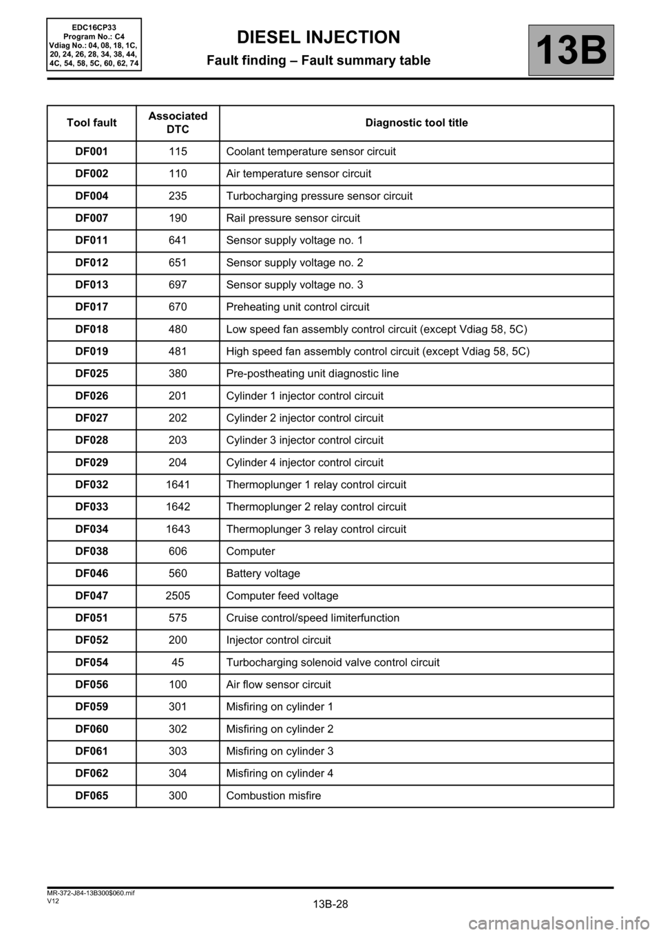
Tool faultAssociated
DTCDiagnostic tool title
DF001115 Coolant temperature sensor circuit
DF002110 Air temperature sensor circuit
DF004235 Turbocharging pressure sensor circuit
DF007190 Rail pressure sensor circuit
DF011641 Sensor supply voltage no. 1
DF012651 Sensor supply voltage no. 2
DF013697 Sensor supply voltage no. 3
DF017670 Preheating unit control circuit
DF018480 Low speed fan assembly control circuit (except Vdiag 58, 5C)
DF019481 High speed fan assembly control circuit (except Vdiag 58, 5C)
DF025380 Pre-postheating unit diagnostic line
DF026201 Cylinder 1 injector control circuit
DF027202 Cylinder 2 injector control circuit
DF028203 Cylinder 3 injector control circuit
DF029204 Cylinder 4 injector control circuit
DF0321641 Thermoplunger 1 relay control circuit
DF0331642 Thermoplunger 2 relay control circuit
DF0341643 Thermoplunger 3 relay control circuit
DF038606 Computer
DF046560 Battery voltage
DF0472505 Computer feed voltage
DF051575 Cruise control/speed limiterfunction
DF052200 Injector control circuit
DF05445 Turbocharging solenoid valve control circuit
DF056100 Air flow sensor circuit
DF059301 Misfiring on cylinder 1
DF060302 Misfiring on cylinder 2
DF061303 Misfiring on cylinder 3
DF062304 Misfiring on cylinder 4
DF065300 Combustion misfire
DIESEL INJECTION
Fault finding – Fault summary table
Page 29 of 510
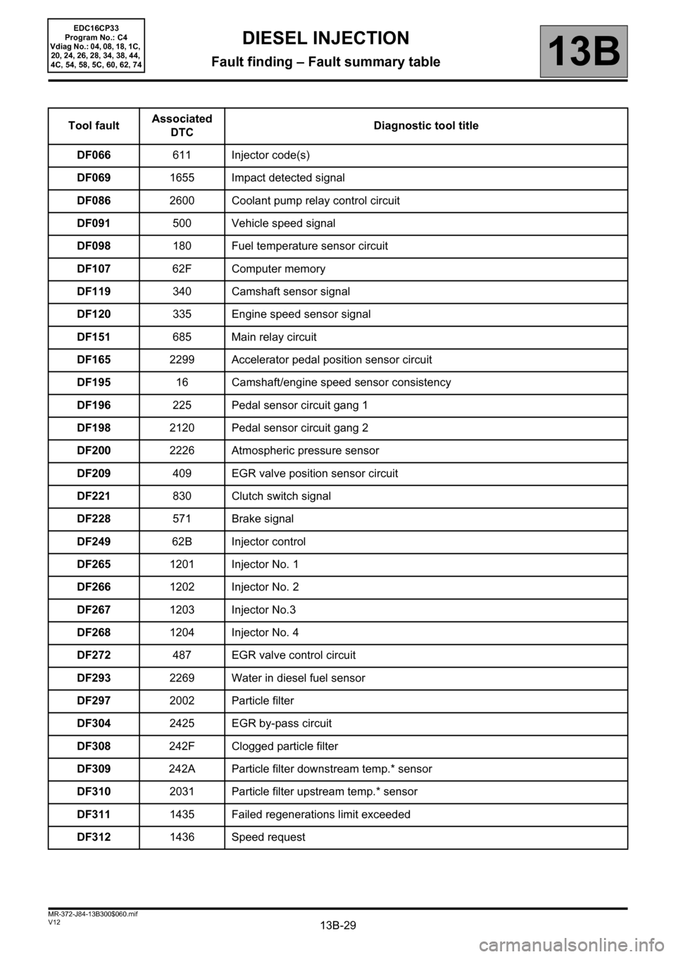
13B-29V12 MR-372-J84-13B300$060.mif
DIESEL INJECTION
Fault finding – Fault summary table13B
EDC16CP33
Program No.: C4
Vdiag No.: 04, 08, 18, 1C,
20, 24, 26, 28, 34, 38, 44,
4C, 54, 58, 5C, 60, 62, 74
Tool faultAssociated
DTCDiagnostic tool title
DF066611 Injector code(s)
DF0691655 Impact detected signal
DF0862600 Coolant pump relay control circuit
DF091500 Vehicle speed signal
DF098180 Fuel temperature sensor circuit
DF10762F Computer memory
DF119340 Camshaft sensor signal
DF120335 Engine speed sensor signal
DF151685 Main relay circuit
DF1652299 Accelerator pedal position sensor circuit
DF19516 Camshaft/engine speed sensor consistency
DF196225 Pedal sensor circuit gang 1
DF1982120 Pedal sensor circuit gang 2
DF2002226 Atmospheric pressure sensor
DF209409 EGR valve position sensor circuit
DF221830 Clutch switch signal
DF228571 Brake signal
DF24962B Injector control
DF2651201 Injector No. 1
DF2661202 Injector No. 2
DF2671203 Injector No.3
DF2681204 Injector No. 4
DF272487 EGR valve control circuit
DF2932269 Water in diesel fuel sensor
DF2972002 Particle filter
DF3042425 EGR by-pass circuit
DF308242F Clogged particle filter
DF309242A Particle filter downstream temp.* sensor
DF3102031 Particle filter upstream temp.* sensor
DF3111435 Failed regenerations limit exceeded
DF3121436 Speed request
Page 30 of 510
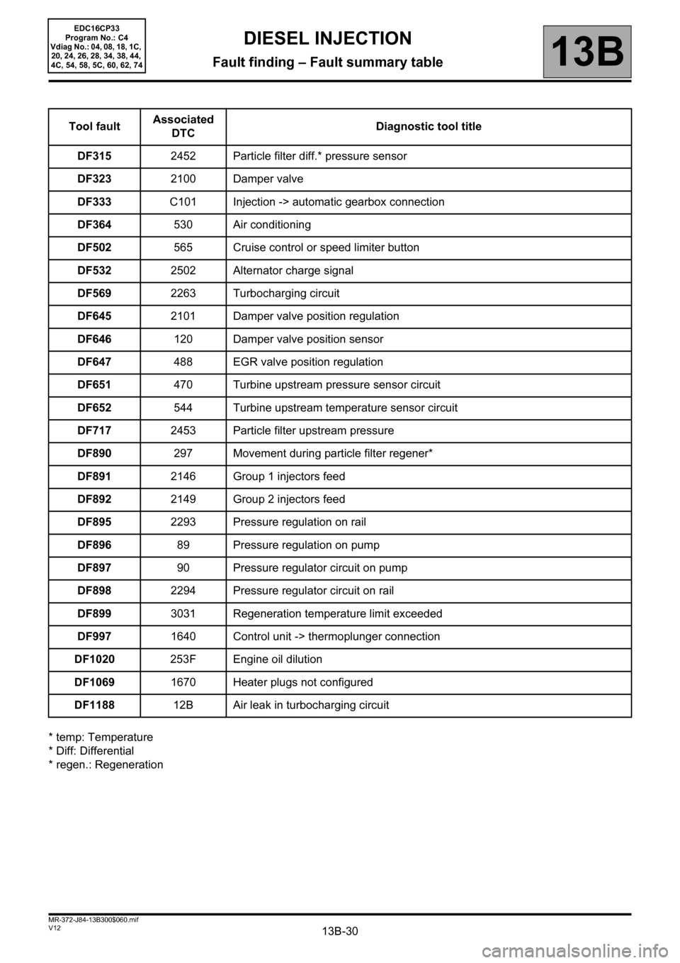
13B-30V12 MR-372-J84-13B300$060.mif
DIESEL INJECTION
Fault finding – Fault summary table13B
EDC16CP33
Program No.: C4
Vdiag No.: 04, 08, 18, 1C,
20, 24, 26, 28, 34, 38, 44,
4C, 54, 58, 5C, 60, 62, 74
* temp: Temperature
* Diff: Differential
* regen.: RegenerationTool faultAssociated
DTCDiagnostic tool title
DF3152452 Particle filter diff.* pressure sensor
DF3232100 Damper valve
DF333C101 Injection -> automatic gearbox connection
DF364530 Air conditioning
DF502565 Cruise control or speed limiter button
DF5322502 Alternator charge signal
DF5692263 Turbocharging circuit
DF6452101 Damper valve position regulation
DF646120 Damper valve position sensor
DF647488 EGR valve position regulation
DF651470 Turbine upstream pressure sensor circuit
DF652544 Turbine upstream temperature sensor circuit
DF7172453 Particle filter upstream pressure
DF890297 Movement during particle filter regener*
DF8912146 Group 1 injectors feed
DF8922149 Group 2 injectors feed
DF8952293 Pressure regulation on rail
DF89689 Pressure regulation on pump
DF89790 Pressure regulator circuit on pump
DF8982294 Pressure regulator circuit on rail
DF8993031 Regeneration temperature limit exceeded
DF9971640 Control unit -> thermoplunger connection
DF1020253F Engine oil dilution
DF10691670 Heater plugs not configured
DF118812B Air leak in turbocharging circuit