lock RENAULT SCENIC 2012 J95 / 3.G Engine And Peripherals EDC16CP33 User Guide
[x] Cancel search | Manufacturer: RENAULT, Model Year: 2012, Model line: SCENIC, Model: RENAULT SCENIC 2012 J95 / 3.GPages: 510, PDF Size: 2.98 MB
Page 198 of 510
13B-198
AFTER REPAIRDeal with any other faults. Clear the fault memory.
Switch off the ignition until the end of the power-latch phase, and carry out a road test
followed by a check with the diagnostic tool.
V12 MR-372-J84-13B300$073.mif
DIESEL INJECTION
Fault finding – Interpretation of faults13B
diff.*: Differential
temp.*: Temperature
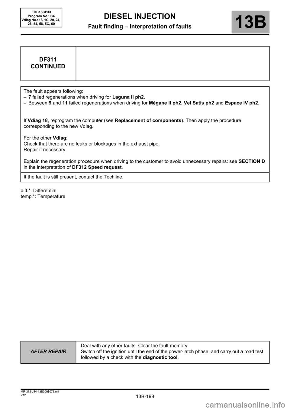
DF311
CONTINUED
The fault appears following:
–7 failed regenerations when driving for Laguna II ph2.
–Between 9 and 11 failed regenerations when driving for Mégane II ph2, Vel Satis ph2 and Espace IV ph2.
If Vdiag 18, reprogram the computer (see Replacement of components). Then apply the procedure
corresponding to the new Vdiag.
For the other Vdiag:
Check that there are no leaks or blockages in the exhaust pipe,
Repair if necessary.
Explain the regeneration procedure when driving to the customer to avoid unnecessary repairs: see SECTION D
in the interpretation of DF312 Speed request.
If the fault is still present, contact the Techline.
EDC16CP33
Program No.: C4
Vdiag No.: 18, 1C, 20, 24,
26, 54, 58, 5C, 60
Page 203 of 510
13B-203
AFTER REPAIRDeal with any other faults. Clear the fault memory.
Switch off the ignition until the end of the power-latch phase, and carry out a road test
followed by a check with the diagnostic tool.
V12 MR-372-J84-13B300$074.mif
13B
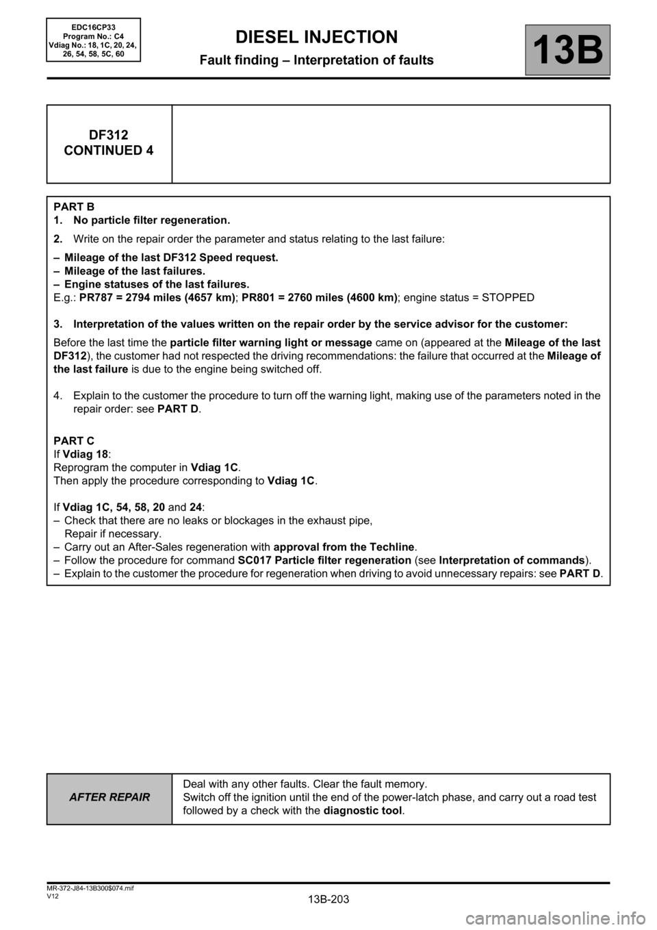
DF312
CONTINUED 4
PART B
1. No particle filter regeneration.
2.Write on the repair order the parameter and status relating to the last failure:
– Mileage of the last DF312 Speed request.
– Mileage of the last failures.
– Engine statuses of the last failures.
E.g.: PR787 = 2794 miles (4657 km); PR801 = 2760 miles (4600 km); engine status = STOPPED
3. Interpretation of the values written on the repair order by the service advisor for the customer:
Before the last time the particle filter warning light or message came on (appeared at the Mileage of the last
DF312), the customer had not respected the driving recommendations: the failure that occurred at the Mileage of
the last failure is due to the engine being switched off.
4. Explain to the customer the procedure to turn off the warning light, making use of the parameters noted in the
repair order: see PART D.
PART C
If Vdiag 18:
Reprogram the computer in Vdiag 1C.
Then apply the procedure corresponding to Vdiag 1C.
If Vdiag 1C, 54, 58, 20 and 24:
– Check that there are no leaks or blockages in the exhaust pipe,
Repair if necessary.
– Carry out an After-Sales regeneration with approval from the Techline.
– Follow the procedure for command SC017 Particle filter regeneration (see Interpretation of commands).
– Explain to the customer the procedure for regeneration when driving to avoid unnecessary repairs: see PART D.
DIESEL INJECTION
Fault finding – Interpretation of faults
EDC16CP33
Program No.: C4
Vdiag No.: 18, 1C, 20, 24,
26, 54, 58, 5C, 60
Page 204 of 510
13B-204
AFTER REPAIRDeal with any other faults. Clear the fault memory.
Switch off the ignition until the end of the power-latch phase, and carry out a road test
followed by a check with the diagnostic tool.
V12 MR-372-J84-13B300$074.mif
DIESEL INJECTION
Fault finding – Interpretation of faults13B
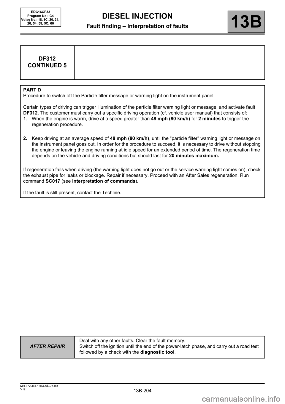
DF312
CONTINUED 5
PART D
Procedure to switch off the Particle filter message or warning light on the instrument panel
Certain types of driving can trigger illumination of the particle filter warning light or message, and activate fault
DF312. The customer must carry out a specific driving operation (cf. vehicle user manual) that consists of:
1. When the engine is warm, drive at a speed greater than 48 mph (80 km/h) for 2 minutes to trigger the
regeneration procedure.
2.Keep driving at an average speed of 48 mph (80 km/h), until the "particle filter" warning light or message on
the instrument panel goes out. In order for the procedure to succeed, it is necessary to drive without stopping
the engine or leaving the engine running at idle speed for an extended period of time. The regeneration time
depends on the vehicle and driving conditions but should last for 20 minutes maximum.
If regeneration fails when driving (the warning light does not go out or the service warning light comes on), check
the exhaust pipe for leaks or blockage. Repair if necessary. Proceed with an After Sales regeneration. Run
command SC017 (see Interpretation of commands).
If the fault is still present, contact the Techline.
EDC16CP33
Program No.: C4
Vdiag No.: 18, 1C, 20, 24,
26, 54, 58, 5C, 60
Page 234 of 510
13B-234
AFTER REPAIRDeal with any other faults. Clear the fault memory.
Switch off the ignition until the end of the power-latch phase, and carry out a road test
followed by a check with the diagnostic tool.
V12 MR-372-J84-13B300$074.mif
DIESEL INJECTION
Fault finding – Interpretation of faults13B
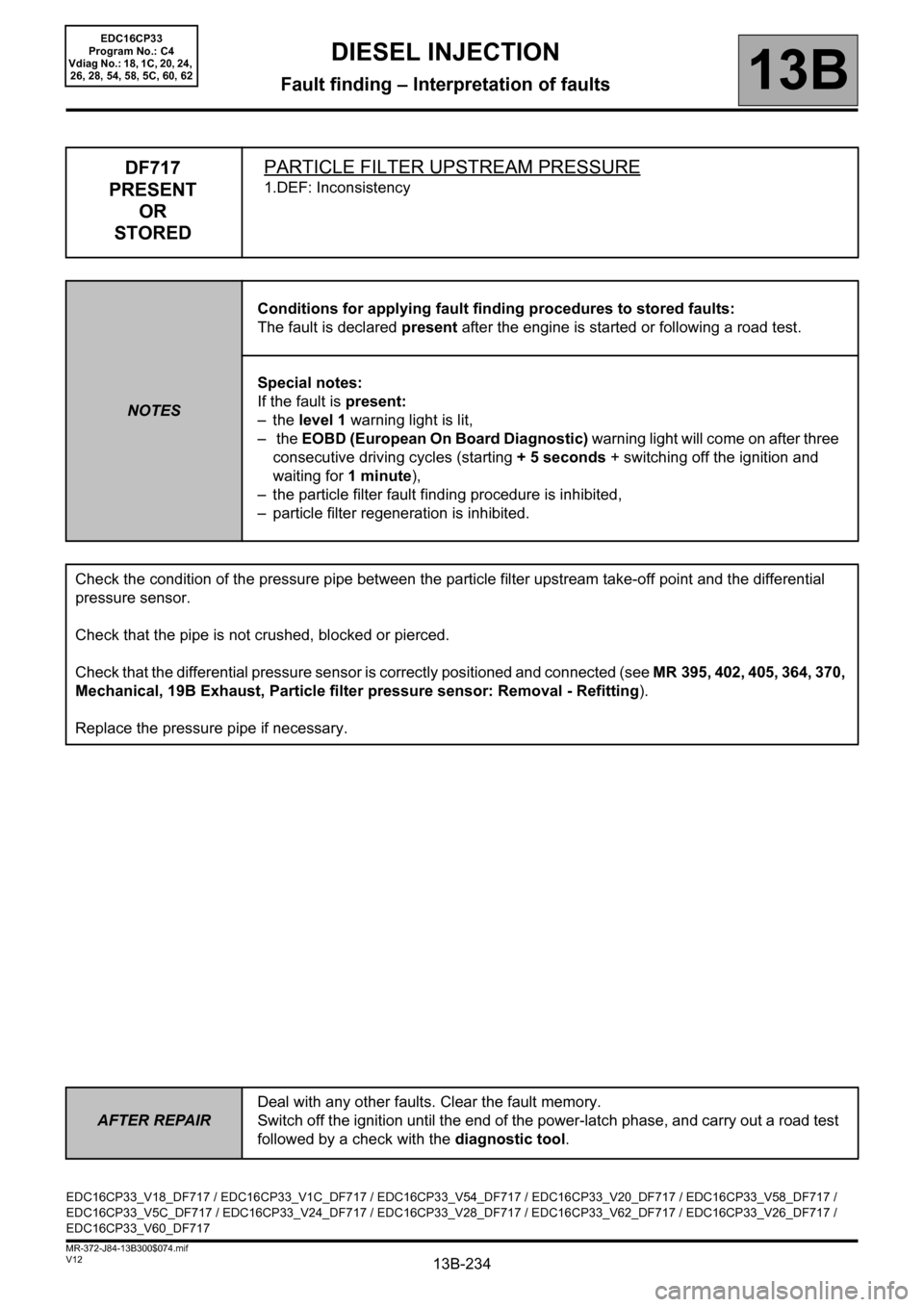
DF717
PRESENT
OR
STOREDPARTICLE FILTER UPSTREAM PRESSURE
1.DEF: Inconsistency
NOTESConditions for applying fault finding procedures to stored faults:
The fault is declared present after the engine is started or following a road test.
Special notes:
If the fault is present:
–the level 1 warning light is lit,
– the EOBD (European On Board Diagnostic) warning light will come on after three
consecutive driving cycles (starting + 5 seconds + switching off the ignition and
waiting for 1 minute),
– the particle filter fault finding procedure is inhibited,
– particle filter regeneration is inhibited.
Check the condition of the pressure pipe between the particle filter upstream take-off point and the differential
pressure sensor.
Check that the pipe is not crushed, blocked or pierced.
Check that the differential pressure sensor is correctly positioned and connected (see MR 395, 402, 405, 364, 370,
Mechanical, 19B Exhaust, Particle filter pressure sensor: Removal - Refitting).
Replace the pressure pipe if necessary.
EDC16CP33_V18_DF717 / EDC16CP33_V1C_DF717 / EDC16CP33_V54_DF717 / EDC16CP33_V20_DF717 / EDC16CP33_V58_DF717 /
EDC16CP33_V5C_DF717 / EDC16CP33_V24_DF717 / EDC16CP33_V28_DF717 / EDC16CP33_V62_DF717 / EDC16CP33_V26_DF717 /
EDC16CP33_V60_DF717
EDC16CP33
Program No.: C4
Vdiag No.: 18, 1C, 20, 24,
26, 28, 54, 58, 5C, 60, 62
Page 265 of 510
13B-265V12 MR-372-J84-13B300$101.mif
DIESEL INJECTION
Fault finding – Interpretation of statuses13B
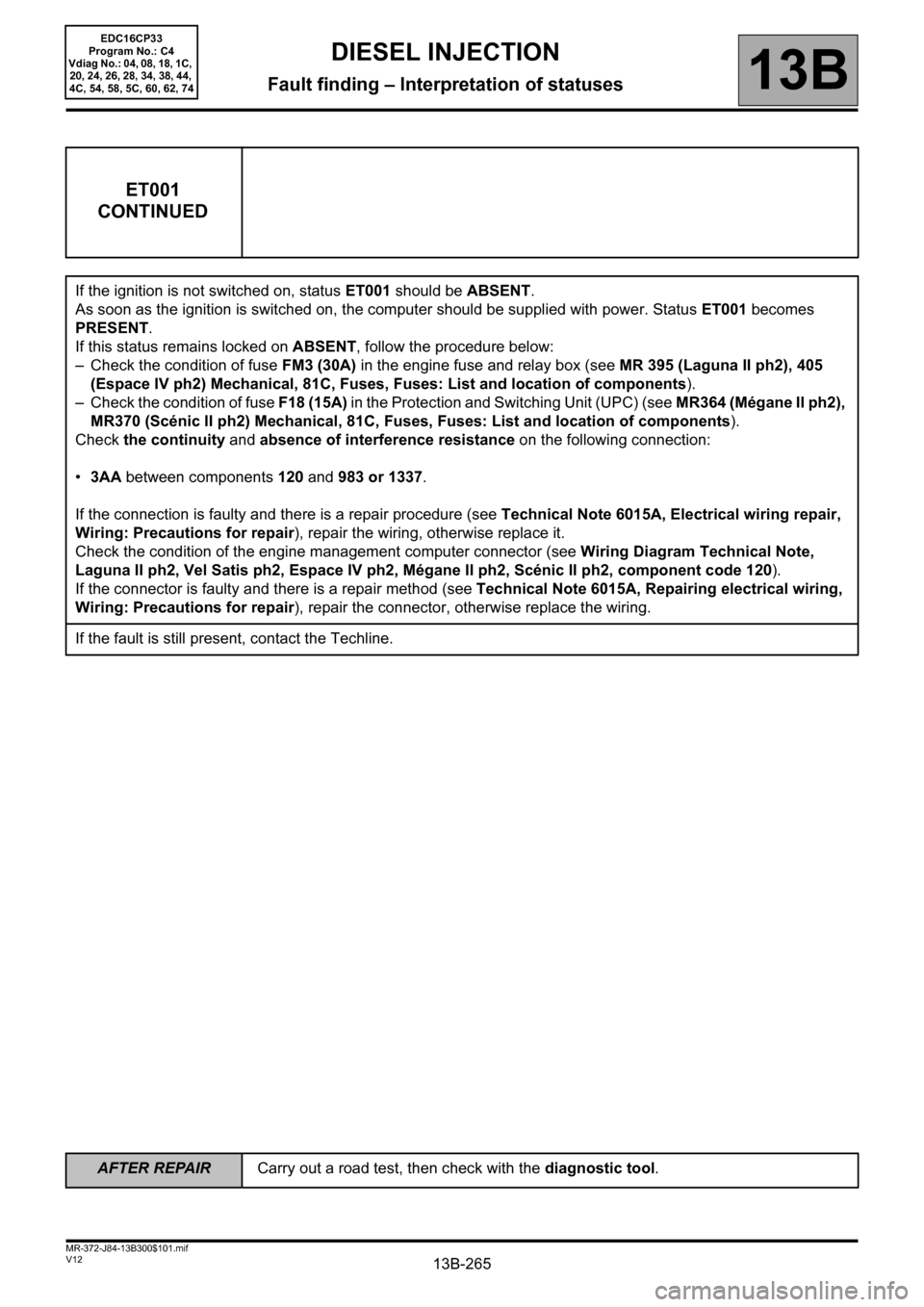
ET001
CONTINUED
If the ignition is not switched on, status ET001 should be ABSENT.
As soon as the ignition is switched on, the computer should be supplied with power. Status ET001 becomes
PRESENT.
If this status remains locked on ABSENT, follow the procedure below:
– Check the condition of fuse FM3 (30A) in the engine fuse and relay box (see MR 395 (Laguna II ph2), 405
(Espace IV ph2) Mechanical, 81C, Fuses, Fuses: List and location of components).
– Check the condition of fuse F18 (15A) in the Protection and Switching Unit (UPC) (see MR364 (Mégane II ph2),
MR370 (Scénic II ph2) Mechanical, 81C, Fuses, Fuses: List and location of components).
Check the continuity and absence of interference resistance on the following connection:
•3AA between components 120 and 983 or 1337.
If the connection is faulty and there is a repair procedure (see Technical Note 6015A, Electrical wiring repair,
Wiring: Precautions for repair), repair the wiring, otherwise replace it.
Check the condition of the engine management computer connector (see Wiring Diagram Technical Note,
Laguna II ph2, Vel Satis ph2, Espace IV ph2, Mégane II ph2, Scénic II ph2, component code 120).
If the connector is faulty and there is a repair method (see Technical Note 6015A, Repairing electrical wiring,
Wiring: Precautions for repair), repair the connector, otherwise replace the wiring.
If the fault is still present, contact the Techline.
EDC16CP33
Program No.: C4
Vdiag No.: 04, 08, 18, 1C,
20, 24, 26, 28, 34, 38, 44,
4C, 54, 58, 5C, 60, 62, 74
AFTER REPAIRCarry out a road test, then check with the diagnostic tool.
Page 299 of 510
13B-299V12 MR-372-J84-13B300$101.mif
DIESEL INJECTION
Fault finding – Interpretation of statuses13B
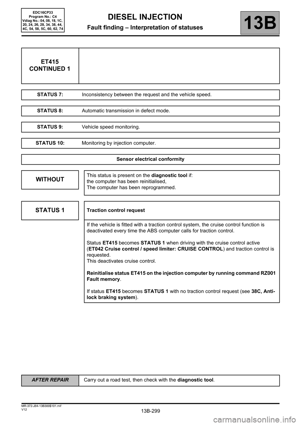
ET415
CONTINUED 1
STATUS 7:Inconsistency between the request and the vehicle speed.
STATUS 8:Automatic transmission in defect mode.
STATUS 9:Vehicle speed monitoring.
STATUS 10:Monitoring by injection computer.
Sensor electrical conformity
WITHOUTThis status is present on the diagnostic tool if:
the computer has been reinitialised,
The computer has been reprogrammed.
STATUS 1Traction control request
If the vehicle is fitted with a traction control system, the cruise control function is
deactivated every time the ABS computer calls for traction control.
Status ET415 becomes STATUS 1 when driving with the cruise control active
(ET042 Cruise control / speed limiter: CRUISE CONTROL) and traction control is
requested.
This deactivates cruise control.
Reinitialise status ET415 on the injection computer by running command RZ001
Fault memory.
If status ET415 becomes STATUS 1 with no traction control request (see 38C, Anti-
lock braking system).
AFTER REPAIRCarry out a road test, then check with the diagnostic tool.
EDC16CP33
Program No.: C4
Vdiag No.: 04, 08, 18, 1C,
20, 24, 26, 28, 34, 38, 44,
4C, 54, 58, 5C, 60, 62, 74
Page 304 of 510
13B-304V12 MR-372-J84-13B300$101.mif
DIESEL INJECTION
Fault finding – Interpretation of statuses13B
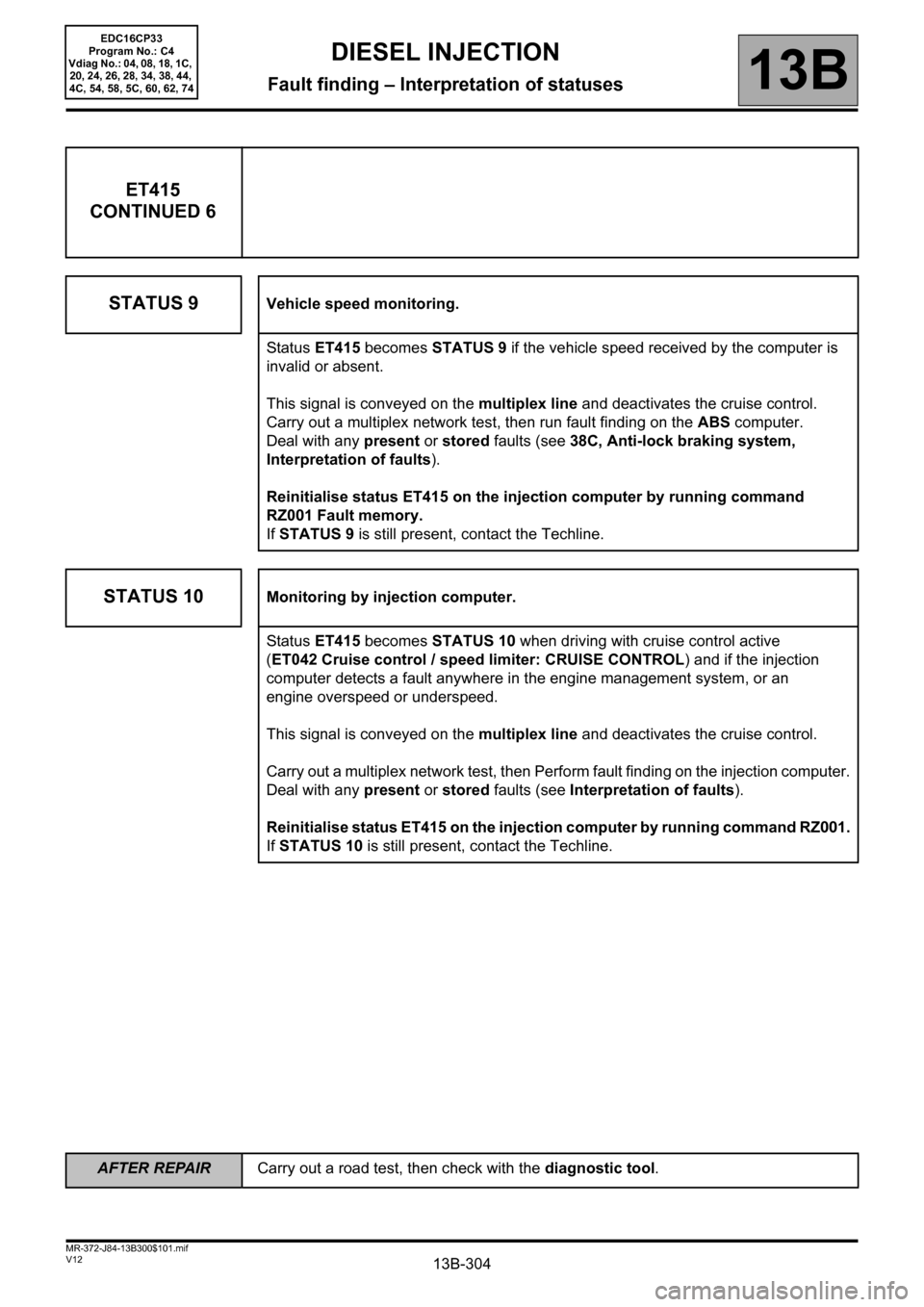
ET415
CONTINUED 6
STATUS 9
Vehicle speed monitoring.
Status ET415 becomes STATUS 9 if the vehicle speed received by the computer is
invalid or absent.
This signal is conveyed on the multiplex line and deactivates the cruise control.
Carry out a multiplex network test, then run fault finding on the ABS computer.
Deal with any present or stored faults (see 38C, Anti-lock braking system,
Interpretation of faults).
Reinitialise status ET415 on the injection computer by running command
RZ001 Fault memory.
If STATUS 9 is still present, contact the Techline.
STATUS 10Monitoring by injection computer.
Status ET415 becomes STATUS 10 when driving with cruise control active
(ET042 Cruise control / speed limiter: CRUISE CONTROL) and if the injection
computer detects a fault anywhere in the engine management system, or an
engine overspeed or underspeed.
This signal is conveyed on the multiplex line and deactivates the cruise control.
Carry out a multiplex network test, then Perform fault finding on the injection computer.
Deal with any present or stored faults (see Interpretation of faults).
Reinitialise status ET415 on the injection computer by running command RZ001.
If STATUS 10 is still present, contact the Techline.
AFTER REPAIRCarry out a road test, then check with the diagnostic tool.
EDC16CP33
Program No.: C4
Vdiag No.: 04, 08, 18, 1C,
20, 24, 26, 28, 34, 38, 44,
4C, 54, 58, 5C, 60, 62, 74
Page 369 of 510
13B-369
AFTER REPAIRCarry out a road test, then check with the diagnostic tool.
V12 MR-372-J84-13B300$121.mif
DIESEL INJECTION
Fault finding – Interpretation of parameters13B
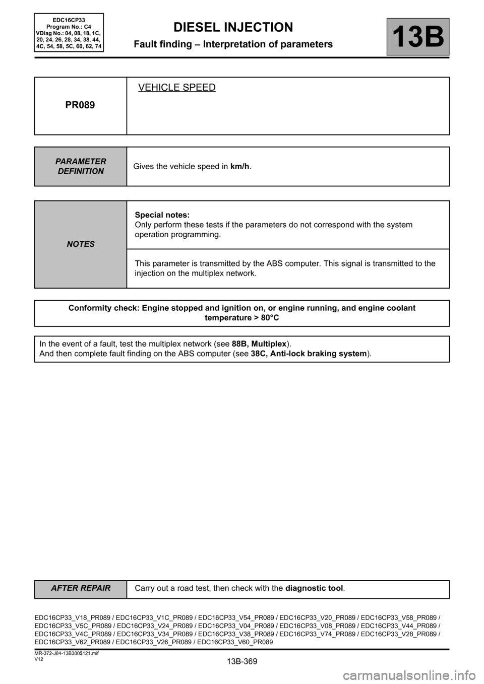
PR089VEHICLE SPEED
PARAMETER
DEFINITIONGives the vehicle speed in km/h.
NOTESSpecial notes:
Only perform these tests if the parameters do not correspond with the system
operation programming.
This parameter is transmitted by the ABS computer. This signal is transmitted to the
injection on the multiplex network.
Conformity check: Engine stopped and ignition on, or engine running, and engine coolant
temperature > 80°C
In the event of a fault, test the multiplex network (see 88B, Multiplex).
And then complete fault finding on the ABS computer (see 38C, Anti-lock braking system).
EDC16CP33_V18_PR089 / EDC16CP33_V1C_PR089 / EDC16CP33_V54_PR089 / EDC16CP33_V20_PR089 / EDC16CP33_V58_PR089 /
EDC16CP33_V5C_PR089 / EDC16CP33_V24_PR089 / EDC16CP33_V04_PR089 / EDC16CP33_V08_PR089 / EDC16CP33_V44_PR089 /
EDC16CP33_V4C_PR089 / EDC16CP33_V34_PR089 / EDC16CP33_V38_PR089 / EDC16CP33_V74_PR089 / EDC16CP33_V28_PR089 /
EDC16CP33_V62_PR089 / EDC16CP33_V26_PR089 / EDC16CP33_V60_PR089
EDC16CP33
Program No.: C4
VDiag No.: 04, 08, 18, 1C,
20, 24, 26, 28, 34, 38, 44,
4C, 54, 58, 5C, 60, 62, 74
Page 375 of 510
13B-375V12 MR-372-J84-13B300$122.mif
DIESEL INJECTION
Fault finding – Interpretation of parameters13B
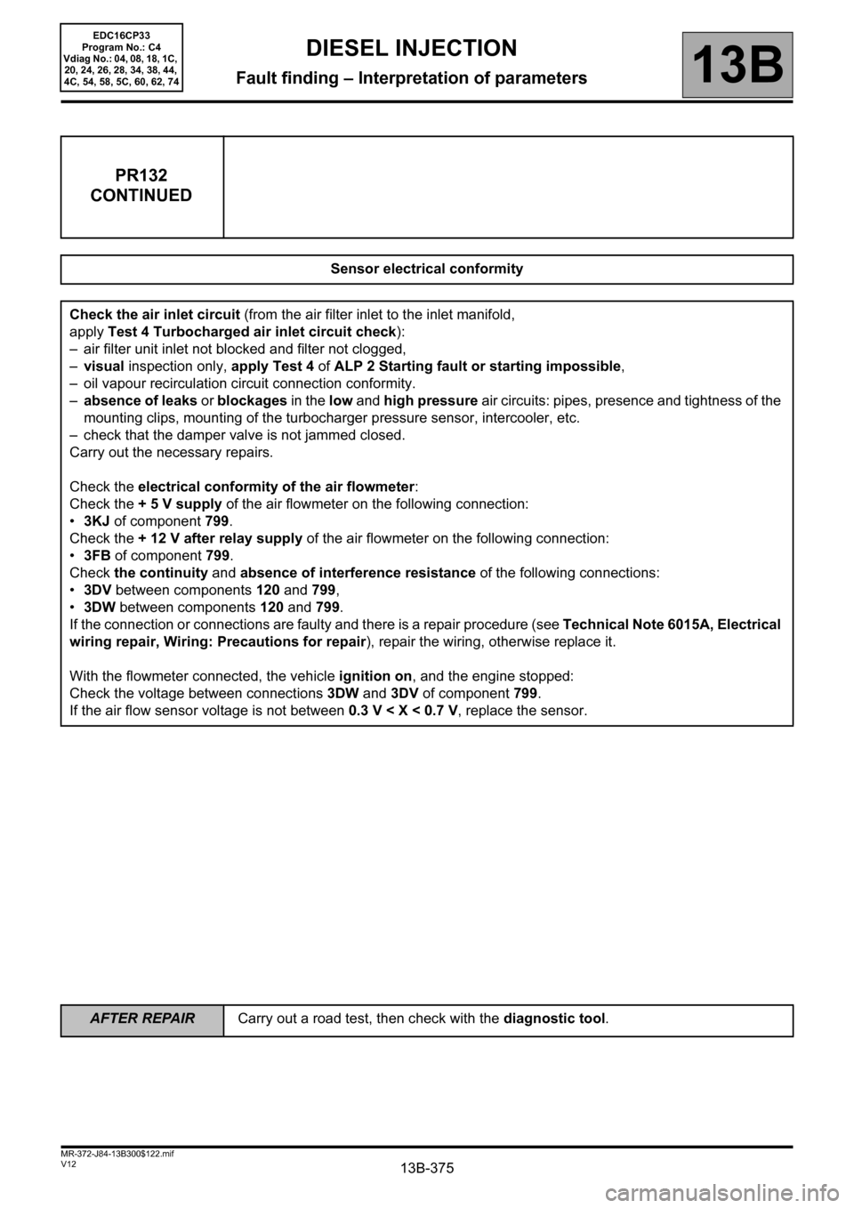
PR132
CONTINUED
Sensor electrical conformity
Check the air inlet circuit (from the air filter inlet to the inlet manifold,
apply Test 4 Turbocharged air inlet circuit check):
– air filter unit inlet not blocked and filter not clogged,
–visual inspection only, apply Test 4 of ALP 2 Starting fault or starting impossible,
– oil vapour recirculation circuit connection conformity.
–absence of leaks or blockages in the low and high pressure air circuits: pipes, presence and tightness of the
mounting clips, mounting of the turbocharger pressure sensor, intercooler, etc.
– check that the damper valve is not jammed closed.
Carry out the necessary repairs.
Check the electrical conformity of the air flowmeter:
Check the + 5 V supply of the air flowmeter on the following connection:
•3KJ of component 799.
Check the + 12 V after relay supply of the air flowmeter on the following connection:
•3FB of component 799.
Check the continuity and absence of interference resistance of the following connections:
•3DV between components 120 and 799,
•3DW between components120 and 799.
If the connection or connections are faulty and there is a repair procedure (see Technical Note 6015A, Electrical
wiring repair, Wiring: Precautions for repair), repair the wiring, otherwise replace it.
With the flowmeter connected, the vehicle ignition on, and the engine stopped:
Check the voltage between connections 3DW and 3DV of component 799.
If the air flow sensor voltage is not between 0.3 V < X < 0.7 V, replace the sensor.
EDC16CP33
Program No.: C4
Vdiag No.: 04, 08, 18, 1C,
20, 24, 26, 28, 34, 38, 44,
4C, 54, 58, 5C, 60, 62, 74
AFTER REPAIRCarry out a road test, then check with the diagnostic tool.
Page 427 of 510
13B-427V12 MR-372-J84-13B300$150.mif
DIESEL INJECTION
Fault finding – Interpretation of commands13B
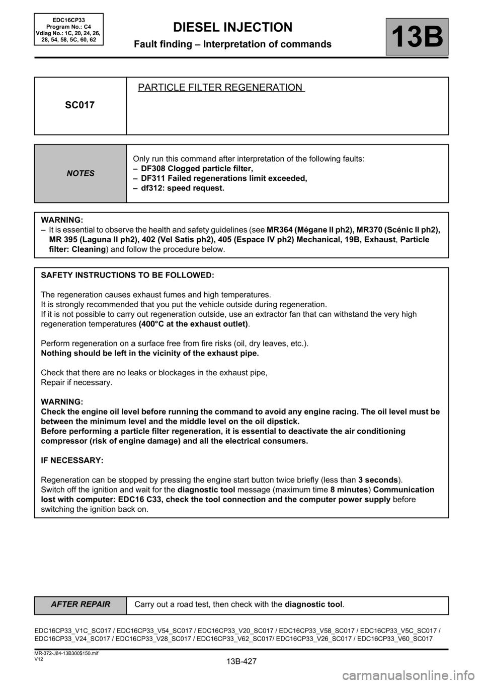
SC017PARTICLE FILTER REGENERATION
NOTESOnly run this command after interpretation of the following faults:
– DF308 Clogged particle filter,
– DF311 Failed regenerations limit exceeded,
– df312: speed request.
WARNING:
– It is essential to observe the health and safety guidelines (see MR364 (Mégane II ph2), MR370 (Scénic II ph2),
MR 395 (Laguna II ph2), 402 (Vel Satis ph2), 405 (Espace IV ph2) Mechanical, 19B, Exhaust, Particle
filter: Cleaning) and follow the procedure below.
SAFETY INSTRUCTIONS TO BE FOLLOWED:
The regeneration causes exhaust fumes and high temperatures.
It is strongly recommended that you put the vehicle outside during regeneration.
If it is not possible to carry out regeneration outside, use an extractor fan that can withstand the very high
regeneration temperatures (400°C at the exhaust outlet).
Perform regeneration on a surface free from fire risks (oil, dry leaves, etc.).
Nothing should be left in the vicinity of the exhaust pipe.
Check that there are no leaks or blockages in the exhaust pipe,
Repair if necessary.
WARNING:
Check the engine oil level before running the command to avoid any engine racing. The oil level must be
between the minimum level and the middle level on the oil dipstick.
Before performing a particle filter regeneration, it is essential to deactivate the air conditioning
compressor (risk of engine damage) and all the electrical consumers.
IF NECESSARY:
Regeneration can be stopped by pressing the engine start button twice briefly (less than 3 seconds).
Switch off the ignition and wait for the diagnostic tool message (maximum time 8 minutes) Communication
lost with computer: EDC16 C33, check the tool connection and the computer power supply before
switching the ignition back on.
EDC16CP33_V1C_SC017 / EDC16CP33_V54_SC017 / EDC16CP33_V20_SC017 / EDC16CP33_V58_SC017 / EDC16CP33_V5C_SC017 /
EDC16CP33_V24_SC017 / EDC16CP33_V28_SC017 / EDC16CP33_V62_SC017/ EDC16CP33_V26_SC017 / EDC16CP33_V60_SC017
EDC16CP33
Program No.: C4
Vdiag No.: 1C, 20, 24, 26,
28, 54, 58, 5C, 60, 62
AFTER REPAIRCarry out a road test, then check with the diagnostic tool.