tire pressure RENAULT SCENIC 2012 J95 / 3.G Engine And Peripherals EDC16CP33 Workshop Manual
[x] Cancel search | Manufacturer: RENAULT, Model Year: 2012, Model line: SCENIC, Model: RENAULT SCENIC 2012 J95 / 3.GPages: 510, PDF Size: 2.98 MB
Page 5 of 510
13B-5V12 MR-372-J84-13B300$010.mif
DIESEL INJECTION
Fault finding – Introduction13B
EDC16CP33
Program No.: C4
Vdiag No.: 04, 08, 18, 1C,
20, 24, 26, 28, 34, 38, 44,
4C, 54, 58, 5C, 60, 62, 74
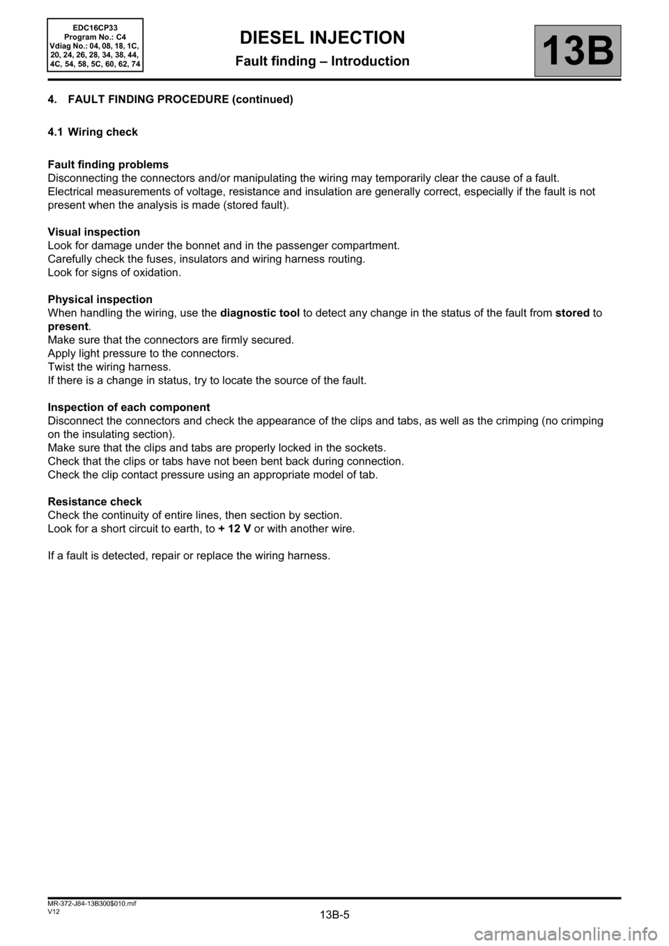
4. FAULT FINDING PROCEDURE (continued)
4.1 Wiring check
Fault finding problems
Disconnecting the connectors and/or manipulating the wiring may temporarily clear the cause of a fault.
Electrical measurements of voltage, resistance and insulation are generally correct, especially if the fault is not
present when the analysis is made (stored fault).
Visual inspection
Look for damage under the bonnet and in the passenger compartment.
Carefully check the fuses, insulators and wiring harness routing.
Look for signs of oxidation.
Physical inspection
When handling the wiring, use the diagnostic tool to detect any change in the status of the fault from stored to
present.
Make sure that the connectors are firmly secured.
Apply light pressure to the connectors.
Twist the wiring harness.
If there is a change in status, try to locate the source of the fault.
Inspection of each component
Disconnect the connectors and check the appearance of the clips and tabs, as well as the crimping (no crimping
on the insulating section).
Make sure that the clips and tabs are properly locked in the sockets.
Check that the clips or tabs have not been bent back during connection.
Check the clip contact pressure using an appropriate model of tab.
Resistance check
Check the continuity of entire lines, then section by section.
Look for a short circuit to earth, to + 12 V or with another wire.
If a fault is detected, repair or replace the wiring harness.
Page 20 of 510
13B-20V12 MR-372-J84-13B300$030.mif
DIESEL INJECTION
Fault finding – System operation13B
EDC16CP33
Program No.: C4
Vdiag No.: 04, 08, 18, 1C,
20, 24, 26, 28, 34, 38, 44,
4C, 54, 58, 5C, 60, 62, 74
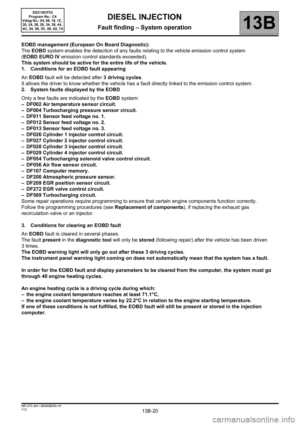
EOBD management (European On Board Diagnostic):
The EOBD system enables the detection of any faults relating to the vehicle emission control system
(EOBD EURO IV emission control standards exceeded).
This system should be active for the entire life of the vehicle.
1. Conditions for an EOBD fault appearing
An EOBD fault will be detected after 3 driving cycles.
It allows the driver to know whether the vehicle has a fault directly linked to the emission control system.
2. System faults displayed by the EOBD
Only a few faults are indicated by the EOBD system:
– DF002 Air temperature sensor circuit.
– DF004 Turbocharging pressure sensor circuit.
– DF011 Sensor feed voltage no. 1.
– DF012 Sensor feed voltage no. 2.
– DF013 Sensor feed voltage no. 3.
– DF026 Cylinder 1 injector control circuit.
– DF027 Cylinder 2 injector control circuit.
– DF028 Cylinder 3 injector control circuit.
– DF029 Cylinder 4 injector control circuit.
– DF054 Turbocharging solenoid valve control circuit.
– DF056 Air flow sensor circuit.
– DF107 Computer memory.
– DF200 Atmospheric pressure sensor.
– DF209 EGR position sensor circuit.
– DF272 EGR valve control circuit.
– DF569 Turbocharging circuit.
Some repair operations require programming to ensure that certain engine components function correctly.
Follow the programming procedures (see Replacement of components), if replacing the exhaust gas
recirculation valve or an injector.
3. Conditions for clearing an EOBD fault
An EOBD fault is cleared in several phases.
The fault present in the diagnostic tool will only be stored (following repair) after the vehicle has been driven
3times.
The EOBD warning light will only go out after these 3 driving cycles.
The instrument panel warning light coming on does not automatically mean that the system has a fault.
In order for the EOBD fault and display parameters to be cleared from the computer, the system must go
through 40 engine heating cycles.
An engine heating cycle is a driving cycle during which:
– the engine coolant temperature reaches at least 71.1°C,
– the engine coolant temperature varies by 22.2°C in relation to the engine starting temperature.
If one of these conditions is not fulfilled, the EOBD fault will still be present or stored in the injection
computer.
Page 220 of 510
13B-220
AFTER REPAIRDeal with any other faults. Clear the fault memory.
Switch off the ignition until the end of the power-latch phase, and carry out a road test
followed by a check with the diagnostic tool.
V12 MR-372-J84-13B300$074.mif
DIESEL INJECTION
Fault finding – Interpretation of faults13B
DF569
CONTINUED 2
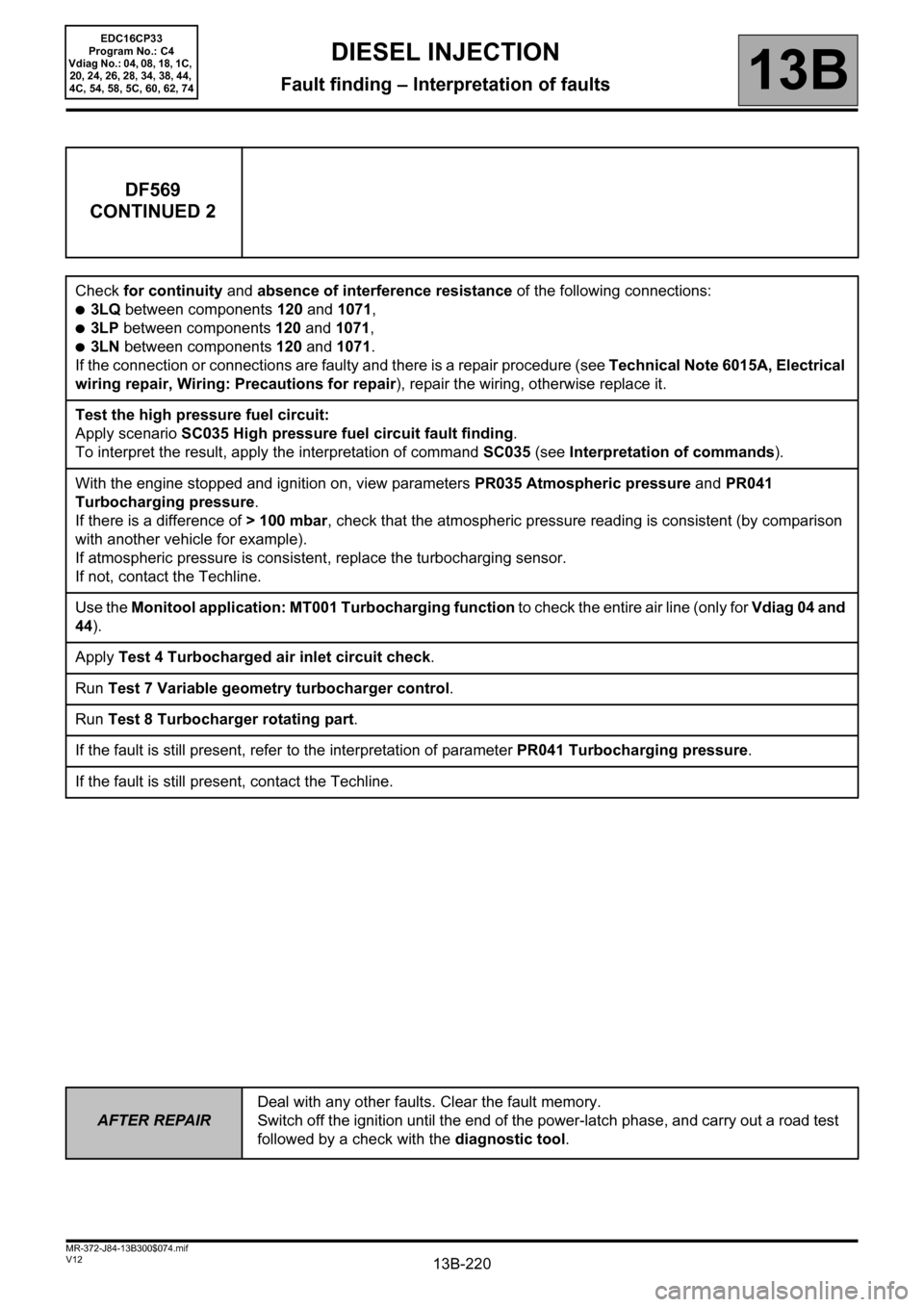
Check for continuity and absence of interference resistance of the following connections:
●3LQ between components 120 and 1071,
●3LP between components 120 and 1071,
●3LN between components 120 and 1071.
If the connection or connections are faulty and there is a repair procedure (see Technical Note 6015A, Electrical
wiring repair, Wiring: Precautions for repair), repair the wiring, otherwise replace it.
Test the high pressure fuel circuit:
Apply scenario SC035 High pressure fuel circuit fault finding.
To interpret the result, apply the interpretation of command SC035 (see Interpretation of commands).
With the engine stopped and ignition on, view parameters PR035 Atmospheric pressure and PR041
Turbocharging pressure.
If there is a difference of > 100 mbar, check that the atmospheric pressure reading is consistent (by comparison
with another vehicle for example).
If atmospheric pressure is consistent, replace the turbocharging sensor.
If not, contact the Techline.
Use the Monitool application: MT001 Turbocharging function to check the entire air line (only for Vdiag 04 and
44).
Apply Test 4 Turbocharged air inlet circuit check.
Run Test 7 Variable geometry turbocharger control.
Run Test 8 Turbocharger rotating part.
If the fault is still present, refer to the interpretation of parameter PR041 Turbocharging pressure.
If the fault is still present, contact the Techline.
EDC16CP33
Program No.: C4
Vdiag No.: 04, 08, 18, 1C,
20, 24, 26, 28, 34, 38, 44,
4C, 54, 58, 5C, 60, 62, 74
Page 433 of 510
13B-433V12 MR-372-J84-13B300$150.mif
DIESEL INJECTION
Fault finding – Interpretation of commands13B
SC035HIGH PRESSURE FUEL CIRCUIT FAULT FINDING
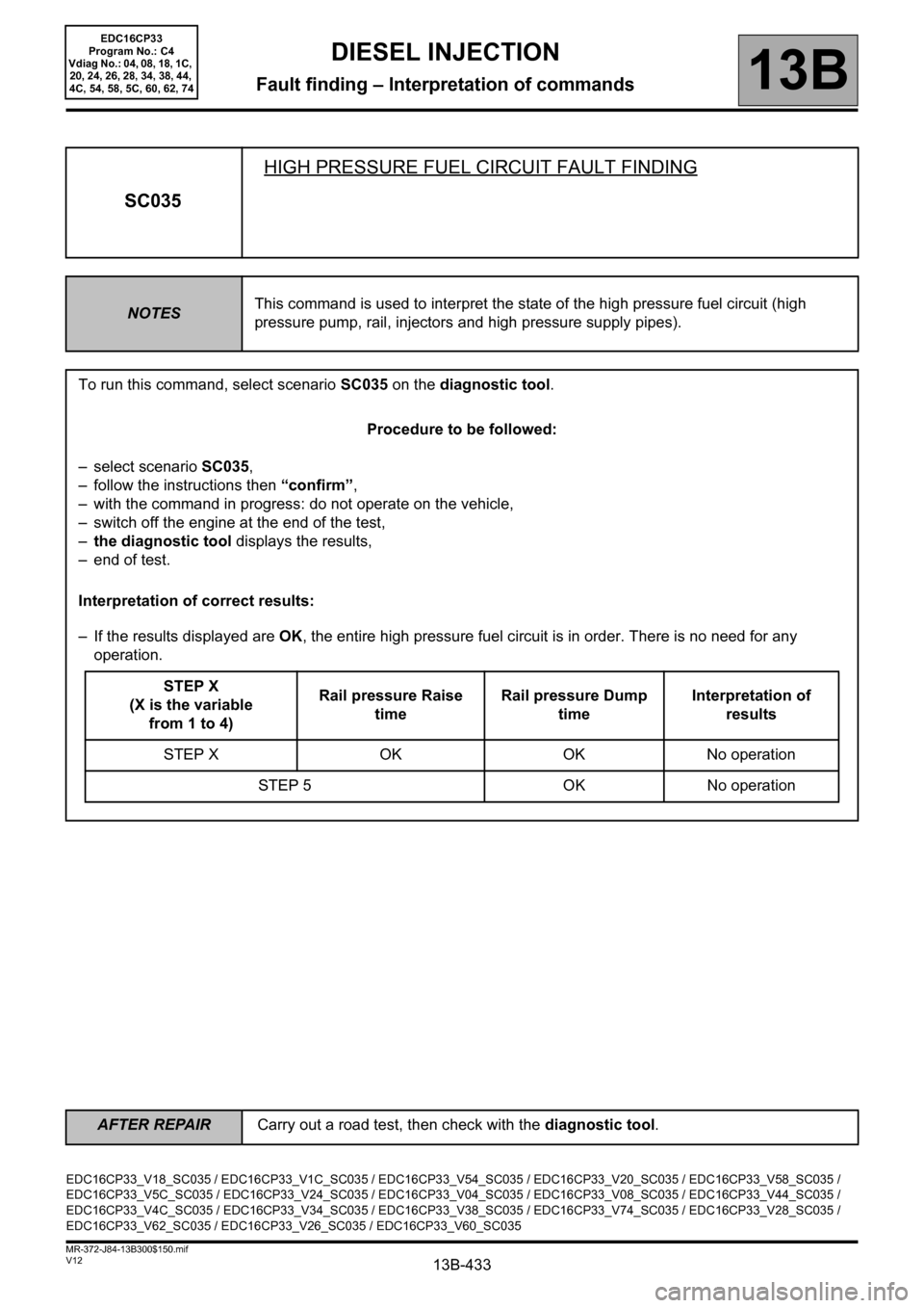
NOTESThis command is used to interpret the state of the high pressure fuel circuit (high
pressure pump, rail, injectors and high pressure supply pipes).
To run this command, select scenario SC035 on the diagnostic tool.
Procedure to be followed:
– select scenario SC035,
– follow the instructions then “confirm”,
– with the command in progress: do not operate on the vehicle,
– switch off the engine at the end of the test,
–the diagnostic tool displays the results,
– end of test.
Interpretation of correct results:
– If the results displayed are OK, the entire high pressure fuel circuit is in order. There is no need for any
operation.
STEP X
(X is the variable
from 1 to 4)Rail pressure Raise
timeRail pressure Dump
timeInterpretation of
results
STEP X OK OK No operation
STEP 5 OK No operation
EDC16CP33_V18_SC035 / EDC16CP33_V1C_SC035 / EDC16CP33_V54_SC035 / EDC16CP33_V20_SC035 / EDC16CP33_V58_SC035 /
EDC16CP33_V5C_SC035 / EDC16CP33_V24_SC035 / EDC16CP33_V04_SC035 / EDC16CP33_V08_SC035 / EDC16CP33_V44_SC035 /
EDC16CP33_V4C_SC035 / EDC16CP33_V34_SC035 / EDC16CP33_V38_SC035 / EDC16CP33_V74_SC035 / EDC16CP33_V28_SC035 /
EDC16CP33_V62_SC035 / EDC16CP33_V26_SC035 / EDC16CP33_V60_SC035
EDC16CP33
Program No.: C4
Vdiag No.: 04, 08, 18, 1C,
20, 24, 26, 28, 34, 38, 44,
4C, 54, 58, 5C, 60, 62, 74
AFTER REPAIRCarry out a road test, then check with the diagnostic tool.
Page 459 of 510
13B-459V12 MR-372-J84-13B300$150.mif
DIESEL INJECTION
Fault finding – Interpretation of commands13B
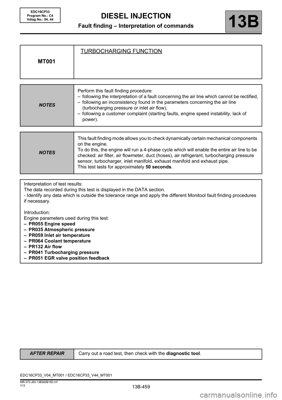
MT001TURBOCHARGING FUNCTION
NOTESPerform this fault finding procedure:
– following the interpretation of a fault concerning the air line which cannot be rectified,
– following an inconsistency found in the parameters concerning the air line
(turbocharging pressure or inlet air flow),
– following a customer complaint (starting faults, engine speed instability, lack of
power).
NOTESThis fault finding mode allows you to check dynamically certain mechanical components
on the engine.
To do this, the engine will run a 4-phase cycle which will enable the entire air line to be
checked: air filter, air flowmeter, duct (hoses), air refrigerant, turbocharging pressure
sensor, turbocharger, inlet manifold, exhaust manifold and exhaust pipe.
This test lasts for approximately 50 seconds.
Interpretation of test results:
The data recorded during this test is displayed in the DATA section.
- Identify any data which is outside the tolerance range and apply the different Monitool fault finding procedures
if necessary.
Introduction:
Engine parameters used during this test:
– PR055 Engine speed
– PR035 Atmospheric pressure
– PR059 Inlet air temperature
– PR064 Coolant temperature
–PR132 Air flow
– PR041 Turbocharging pressure
– PR051 EGR valve position feedback
EDC16CP33_V04_MT001 / EDC16CP33_V44_MT001
EDC16CP33
Program No.: C4
Vdiag No.: 04, 44
AFTER REPAIRCarry out a road test, then check with the diagnostic tool.
Page 497 of 510
13B-497V12 MR-372-J84-13B300$180.mif
DIESEL INJECTION
Fault finding – Test13B
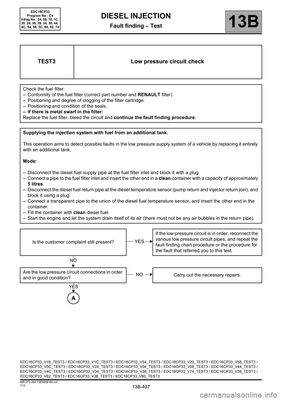
TEST3 Low pressure circuit check
Check the fuel filter:
– Conformity of the fuel filter (correct part number and RENAULT filter).
– Positioning and degree of clogging of the filter cartridge.
– Positioning and condition of the seals.
– If there is metal swarf in the filter:
Replace the fuel filter, bleed the circuit and continue the fault finding procedure.
Supplying the injection system with fuel from an additional tank.
This operation aims to detect possible faults in the low pressure supply system of a vehicle by replacing it entirely
with an additional tank.
Mode:
– Disconnect the diesel fuel supply pipe at the fuel filter inlet and block it with a plug.
– Connect a pipe to the fuel filter inlet and insert the other end in a clean container with a capacity of approximately
5 litres.
– Disconnect the diesel fuel return pipe at the diesel temperature sensor (pump return and injector return join), and
block it using a plug.
– Connect a transparent pipe to the union of the diesel fuel temperature sensor, and insert the other end in the
container.
– Fill the container with clean diesel fuel.
– Start the engine and let the system drain itself of its air (there must not be any air bubbles in the return pipe).
Is the customer complaint still present?If the low pressure circuit is in order, reconnect the
various low pressure circuit pipes, and repeat the
fault finding chart procedure or the procedure for
the fault that referred you to this test.
Are the low pressure circuit connections in order
and in good condition?Carry out the necessary repairs.
YES
NO
NO
A
YES
EDC16CP33_V18_TEST3 / EDC16CP33_V1C_TEST3 / EDC16CP33_V54_TEST3 / EDC16CP33_V20_TEST3 / EDC16CP33_V58_TEST3 /
EDC16CP33_V5C_TEST3 / EDC16CP33_V24_TEST3 / EDC16CP33_V04_TEST3 / EDC16CP33_V08_TEST3 / EDC16CP33_V44_TEST3 /
EDC16CP33_V4C_TEST3 / EDC16CP33_V34_TEST3 / EDC16CP33_V38_TEST3 / EDC16CP33_V74_TEST3 / EDC16CP33_V28_TEST3 /
EDC16CP33_V62_TEST3 / EDC16CP33_V26_TEST3 / EDC16CP33_V60_TEST3
EDC16CP33
Program No.: C4
Vdiag No.: 04, 08, 18, 1C,
20, 24, 26, 28, 34, 38, 44,
4C, 54, 58, 5C, 60, 62, 74