check engine RENAULT SCENIC 2012 J95 / 3.G Engine And Peripherals EDC16CP33 Workshop Manual
[x] Cancel search | Manufacturer: RENAULT, Model Year: 2012, Model line: SCENIC, Model: RENAULT SCENIC 2012 J95 / 3.GPages: 510, PDF Size: 2.98 MB
Page 284 of 510
13B-284V12 MR-372-J84-13B300$101.mif
DIESEL INJECTION
Fault finding – Interpretation of statuses13B
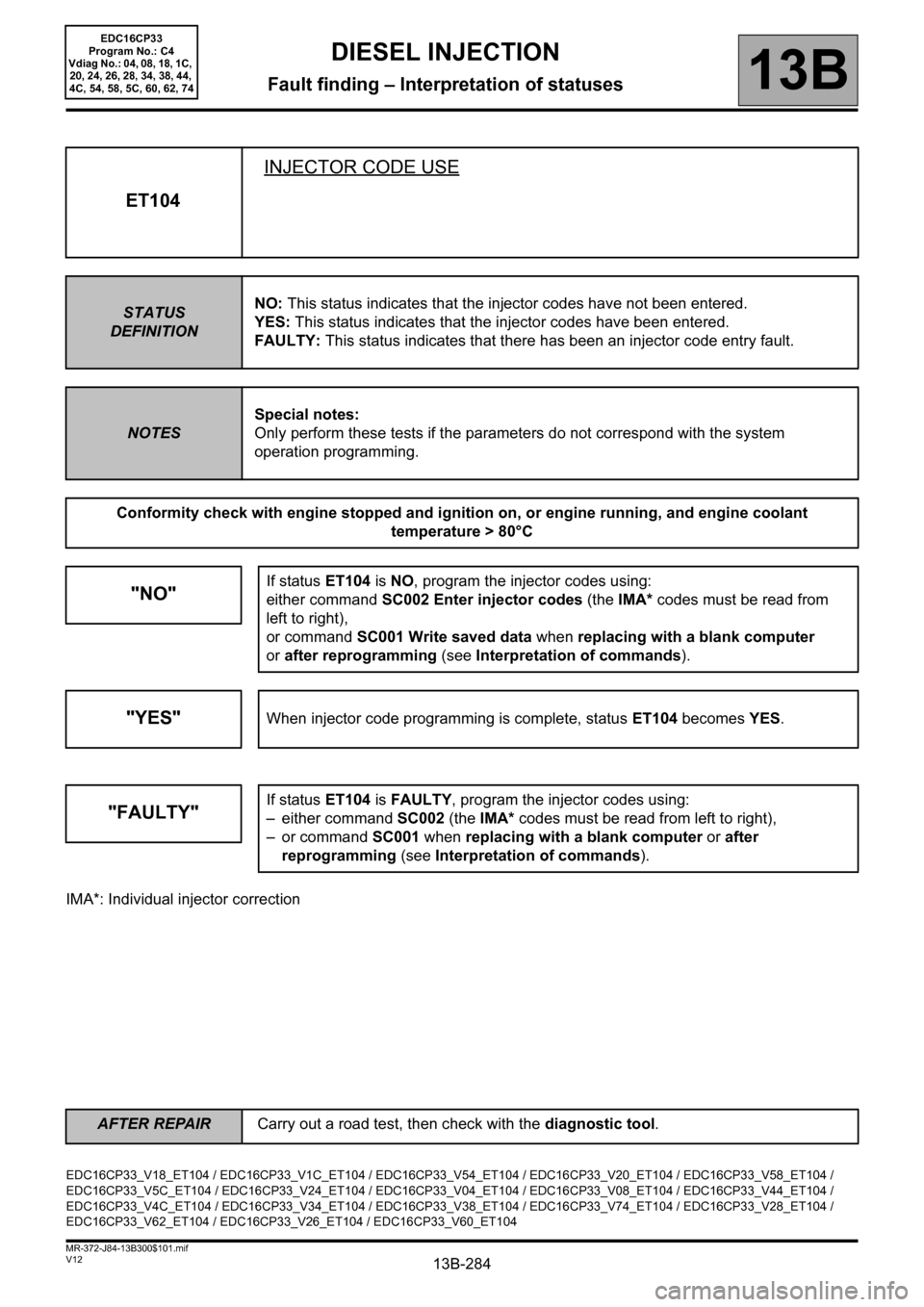
IMA*: Individual injector correction
ET104INJECTOR CODE USE
STATUS
DEFINITIONNO: This status indicates that the injector codes have not been entered.
YES: This status indicates that the injector codes have been entered.
FAULTY: This status indicates that there has been an injector code entry fault.
NOTESSpecial notes:
Only perform these tests if the parameters do not correspond with the system
operation programming.
Conformity check with engine stopped and ignition on, or engine running, and engine coolant
temperature > 80°C
"NO"If status ET104 is NO, program the injector codes using:
either command SC002 Enter injector codes (the IMA* codes must be read from
left to right),
or command SC001 Write saved data when replacing with a blank computer
orafter reprogramming (see Interpretation of commands).
"YES"When injector code programming is complete, status ET104 becomes YES.
"FAULTY"If status ET104 is FAULTY, program the injector codes using:
– either command SC002 (the IMA* codes must be read from left to right),
– or command SC001 when replacing with a blank computer or after
reprogramming (see Interpretation of commands).
EDC16CP33_V18_ET104 / EDC16CP33_V1C_ET104 / EDC16CP33_V54_ET104 / EDC16CP33_V20_ET104 / EDC16CP33_V58_ET104 /
EDC16CP33_V5C_ET104 / EDC16CP33_V24_ET104 / EDC16CP33_V04_ET104 / EDC16CP33_V08_ET104 / EDC16CP33_V44_ET104 /
EDC16CP33_V4C_ET104 / EDC16CP33_V34_ET104 / EDC16CP33_V38_ET104 / EDC16CP33_V74_ET104 / EDC16CP33_V28_ET104 /
EDC16CP33_V62_ET104 / EDC16CP33_V26_ET104 / EDC16CP33_V60_ET104
AFTER REPAIRCarry out a road test, then check with the diagnostic tool.
EDC16CP33
Program No.: C4
Vdiag No.: 04, 08, 18, 1C,
20, 24, 26, 28, 34, 38, 44,
4C, 54, 58, 5C, 60, 62, 74
Page 285 of 510
13B-285V12 MR-372-J84-13B300$101.mif
DIESEL INJECTION
Fault finding – Interpretation of statuses13B
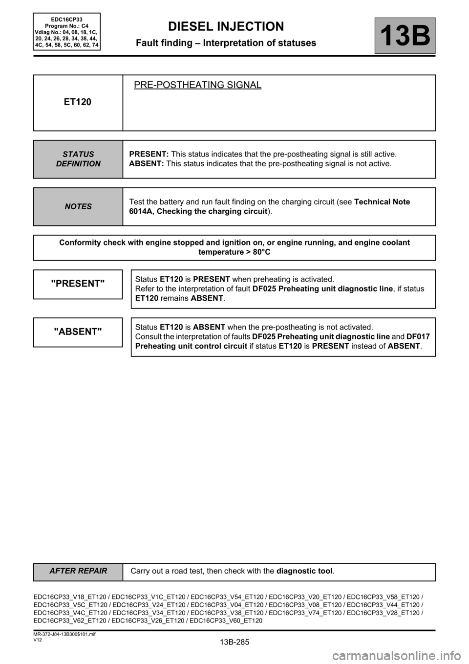
ET120PRE-POSTHEATING SIGNAL
STATUS
DEFINITIONPRESENT: This status indicates that the pre-postheating signal is still active.
ABSENT: This status indicates that the pre-postheating signal is not active.
NOTESTest the battery and run fault finding on the charging circuit (see Technical Note
6014A, Checking the charging circuit).
Conformity check with engine stopped and ignition on, or engine running, and engine coolant
temperature > 80°C
"PRESENT"Status ET120 is PRESENT when preheating is activated.
Refer to the interpretation of fault DF025 Preheating unit diagnostic line, if status
ET120 remains ABSENT.
"ABSENT"Status ET120 is ABSENT when the pre-postheating is not activated.
Consult the interpretation of faults DF025 Preheating unit diagnostic line and DF017
Preheating unit control circuit if status ET120 is PRESENT instead of ABSENT.
EDC16CP33_V18_ET120 / EDC16CP33_V1C_ET120 / EDC16CP33_V54_ET120 / EDC16CP33_V20_ET120 / EDC16CP33_V58_ET120 /
EDC16CP33_V5C_ET120 / EDC16CP33_V24_ET120 / EDC16CP33_V04_ET120 / EDC16CP33_V08_ET120 / EDC16CP33_V44_ET120 /
EDC16CP33_V4C_ET120 / EDC16CP33_V34_ET120 / EDC16CP33_V38_ET120 / EDC16CP33_V74_ET120 / EDC16CP33_V28_ET120 /
EDC16CP33_V62_ET120 / EDC16CP33_V26_ET120 / EDC16CP33_V60_ET120
AFTER REPAIRCarry out a road test, then check with the diagnostic tool.
EDC16CP33
Program No.: C4
Vdiag No.: 04, 08, 18, 1C,
20, 24, 26, 28, 34, 38, 44,
4C, 54, 58, 5C, 60, 62, 74
Page 286 of 510
13B-286V12 MR-372-J84-13B300$101.mif
DIESEL INJECTION
Fault finding – Interpretation of statuses13B
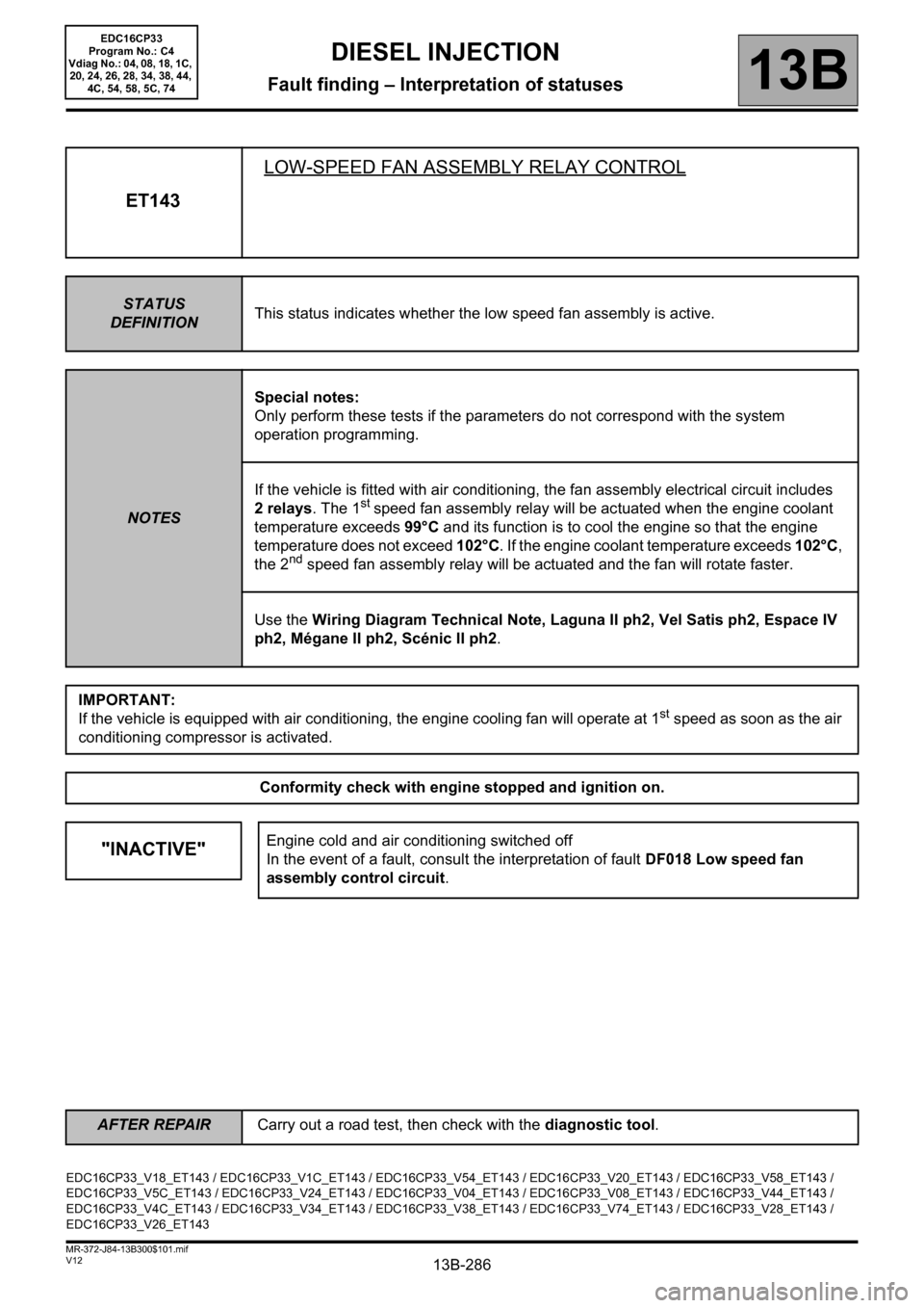
ET143LOW-SPEED FAN ASSEMBLY RELAY CONTROL
STATUS
DEFINITIONThis status indicates whether the low speed fan assembly is active.
NOTESSpecial notes:
Only perform these tests if the parameters do not correspond with the system
operation programming.
If the vehicle is fitted with air conditioning, the fan assembly electrical circuit includes
2 relays. The 1
st speed fan assembly relay will be actuated when the engine coolant
temperature exceeds 99°C and its function is to cool the engine so that the engine
temperature does not exceed 102°C. If the engine coolant temperature exceeds 102°C,
the 2
nd speed fan assembly relay will be actuated and the fan will rotate faster.
Use the Wiring Diagram Technical Note, Laguna II ph2, Vel Satis ph2, Espace IV
ph2, Mégane II ph2, Scénic II ph2.
IMPORTANT:
If the vehicle is equipped with air conditioning, the engine cooling fan will operate at 1
st speed as soon as the air
conditioning compressor is activated.
Conformity check with engine stopped and ignition on.
"INACTIVE"Engine cold and air conditioning switched off
In the event of a fault, consult the interpretation of fault DF018 Low speed fan
assembly control circuit.
EDC16CP33_V18_ET143 / EDC16CP33_V1C_ET143 / EDC16CP33_V54_ET143 / EDC16CP33_V20_ET143 / EDC16CP33_V58_ET143 /
EDC16CP33_V5C_ET143 / EDC16CP33_V24_ET143 / EDC16CP33_V04_ET143 / EDC16CP33_V08_ET143 / EDC16CP33_V44_ET143 /
EDC16CP33_V4C_ET143 / EDC16CP33_V34_ET143 / EDC16CP33_V38_ET143 / EDC16CP33_V74_ET143 / EDC16CP33_V28_ET143 /
EDC16CP33_V26_ET143
AFTER REPAIRCarry out a road test, then check with the diagnostic tool.
EDC16CP33
Program No.: C4
Vdiag No.: 04, 08, 18, 1C,
20, 24, 26, 28, 34, 38, 44,
4C, 54, 58, 5C, 74
Page 287 of 510
13B-287V12 MR-372-J84-13B300$101.mif
DIESEL INJECTION
Fault finding – Interpretation of statuses13B
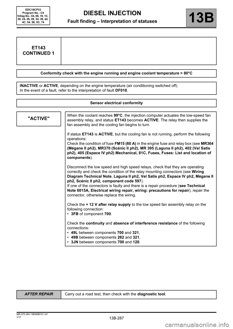
ET143
CONTINUED 1
Conformity check with the engine running and engine coolant temperature > 80°C
INACTIVE or ACTIVE, depending on the engine temperature (air conditioning switched off).
In the event of a fault, refer to the interpretation of fault DF018.
Sensor electrical conformity
"ACTIVE"When the coolant reaches 99°C, the injection computer actuates the low-speed fan
assembly relay, and status ET143 becomes ACTIVE. The relay then supplies the
fan assembly and the cooling fan begins to turn.
If status ET143 is ACTIVE, but the cooling fan is not running, perform the following
operations:
Check the condition of fuse FM15 (60 A) in the engine fuse and relay box (see MR364
(Mégane II ph2), MR370 (Scénic II ph2), MR 395 (Laguna II ph2), 402 (Vel Satis
ph2), 405 (Espace IV ph2) Mechanical, 81C, Fuses, Fuses: List and location of
components).
Disconnect the low speed and high speed relays, check that they are operating
correctly and check the condition of the relay mounting connectors (see Wiring
Diagram Technical Note, Laguna II ph2, Vel Satis ph2, Espace IV ph2, Mégane II
ph2, Scénic II ph2, component code 597).
If one of the connectors is faulty and there is a repair procedure (see Technical
Note 6015A, Electrical wiring repair, wiring: precautions for repair), repair the
connector, otherwise replace the wiring.
Check the + 12 V after relay supply to the low speed fan assembly relay on the
following connection:
•3FB of component 700.
Check the continuity and absence of interference resistance of the following
connections:
•49L between components 700 and 321,
•49B between components 262 and 321,
•3JN between components 700 and 120.
AFTER REPAIRCarry out a road test, then check with the diagnostic tool.
EDC16CP33
Program No.: C4
Vdiag No.: 04, 08, 18, 1C,
20, 24, 26, 28, 34, 38, 44,
4C, 54, 58, 5C, 74
Page 288 of 510
13B-288V12 MR-372-J84-13B300$101.mif
DIESEL INJECTION
Fault finding – Interpretation of statuses13B
ET143
CONTINUED 2
"ACTIVE"
Check that the earth is in order on connection MAS of component 262.
If the connection or connections are faulty and there is a repair procedure (see
Technical Note 6015A, Electrical wiring repair, Wiring: Precautions for repair),
repair the wiring, otherwise replace it.
"INACTIVE"If the engine temperature is lower than 99°C, the engine cooling fan cannot switch
on and the low speed fan relay of the cannot be run.
Status ET143 should therefore be INACTIVE when the control relay and the engine
cooling fan are not supplied.
AFTER REPAIRCarry out a road test, then check with the diagnostic tool.
EDC16CP33
Program No.: C4
Vdiag No.: 04, 08, 18, 1C,
20, 24, 26, 28, 34, 38, 44,
4C, 54, 58, 5C, 74
Page 289 of 510
13B-289V12 MR-372-J84-13B300$101.mif
DIESEL INJECTION
Fault finding – Interpretation of statuses13B
ET144HIGH-SPEED FAN ASSEMBLY RELAY CONTROL
STATUS
DEFINITIONThis status indicates whether the high speed fan assembly is active.
NOTESSpecial notes:
Only perform these tests if the parameters do not correspond with the system
operation programming.
If the vehicle is not fitted with air conditioning, low-speed fan assembly relay does not
exist. The circuit therefor only contains a single command relay to supply the engine
cooling fan. The engine cooling fan will thus have only one operating speed.
Use the Wiring Diagram Technical Note, Laguna II ph2, Vel Satis ph2, Espace IV
ph2, Mégane II ph2, Scénic II ph2.
Conformity check with engine stopped and ignition on.
"INACTIVE"Engine cold and air conditioning switched off
In the event of a fault, consult the interpretation of fault DF019 High speed fan
assembly control circuit.
Conformity check with the engine running and engine coolant temperature > 80°C
INACTIVE or ACTIVE, depending on the engine temperature (air conditioning switched off).
In the event of a fault, refer to the interpretation of fault DF019.
EDC16CP33_V18_ET144 / EDC16CP33_V1C_ET144 / EDC16CP33_V54_ET144 / EDC16CP33_V20_ET144 / EDC16CP33_V58_ET144 /
EDC16CP33_V5C_ET144 / EDC16CP33_V24_ET144 / EDC16CP33_V04_ET144 / EDC16CP33_V08_ET144 / EDC16CP33_V44_ET144 /
EDC16CP33_V4C_ET144 / EDC16CP33_V34_ET144 / EDC16CP33_V38_ET144 / EDC16CP33_V74_ET144 / EDC16CP33_V28_ET144 /
EDC16CP33_V26_ET144
AFTER REPAIRCarry out a road test, then check with the diagnostic tool.
EDC16CP33
Program No.: C4
Vdiag No.: 04, 08, 18, 1C,
20, 24, 26, 28, 34, 38, 44,
4C, 54, 58, 5C, 74
Page 290 of 510
13B-290V12 MR-372-J84-13B300$101.mif
DIESEL INJECTION
Fault finding – Interpretation of statuses13B
ET144
CONTINUED 1
Sensor electrical conformity
"ACTIVE"When the coolant reaches 102°C, the injection computer actuates the fan assembly
relay and status ET144 becomes ACTIVE. The relay then supplies the cooling fan.
If status ET144 is ACTIVE, but the cooling fan is not running, perform the following
operations:
Check the condition of fuse FM15 (60 A) in the engine fuse and relay box (see MR364
(Mégane II ph2), MR370 (Scénic II ph2), MR 395 (Laguna II ph2), 402 (Vel Satis
ph2), 405 (Espace IV ph2) Mechanical, 81C, Fuses, Fuses: List and location of
components).
Disconnect the low speed and high speed relays, check that they are operating
correctly and check the condition of the relay mounting connectors (see Wiring
Diagram Technical Note, Laguna II ph2, Vel Satis ph2, Espace IV ph2, Mégane II
ph2, Scénic II ph2, component code 597).
If one of the connectors is faulty and there is a repair procedure (see Technical
Note 6015A, Electrical wiring repair, wiring: precautions for repair), repair the
connector, otherwise replace the wiring.
Check the + 12 V after relay supply to the high-speed fan assembly relay on the
following connection:
•3FB of component 234.
Check the continuity and absence of interference resistance of the following
connections:
•3JP between components 234 and 120,
•49B between components 234 and 262.
Check that the earth is in order on connection MAS of component 262.
If the connection or connections are faulty and there is a repair procedure (see
Technical Note 6015A, Electrical wiring repair, Wiring: Precautions for repair),
repair the wiring, otherwise replace it.
AFTER REPAIRCarry out a road test, then check with the diagnostic tool.
EDC16CP33
Program No.: C4
Vdiag No.: 04, 08, 18, 1C,
20, 24, 26, 28, 34, 38, 44,
4C, 54, 58, 5C, 74
Page 292 of 510
13B-292V12 MR-372-J84-13B300$101.mif
DIESEL INJECTION
Fault finding – Interpretation of statuses13B
Only for Laguna II ph2 without a particle filter
ET205
ET206
ET207THERMOPLUNGER 1 RELAY CONTROLTHERMOPLUNGER 2 RELAY CONTROL
THERMOPLUNGER 3 RELAY CONTROL
STATUS
DEFINITIONACTIVE: This status indicates that the thermoplunger is supplied.
INACTIVE: This status indicates that the thermoplunger is not supplied.
NOTESNone.
"INACTIVE"Statuses ET205, ET206, ET207 are INACTIVE when the ignition is switched on
and the engine stopped, or when the engine is warm.
"ACTIVE"Statuses ET205, ET206 and ET207 are ACTIVE when the engine is started, the
engine coolant temperature is low (<15°C) and the air temperature is low (<5°).
This program allows the engine coolant to be heated to enable the passenger
compartment to be heated.
The thermoplungers also act both to load the engine to improve regeneration of
the particle filter.
To control the operation of the thermoplunger relays, run the following commands:
– AC063 Thermoplunger no.1 relay,
– AC064 Thermoplunger no. 2 relay,
– AC031 Thermoplunger no.3 relay.
In the event of a fault, refer to the interpretation of faults:
– DF034 "Thermoplunger 3 relay control circuit",
– DF033 "Heating element 2 relay control circuit",
– DF032 Thermoplunger 1 relay control circuit.
EDC16CP33_V04_ET205 / EDC16CP33_V04_ET206 / EDC16CP33_V04_ET207 / EDC16CP33_V08_ET205 / EDC16CP33_V08_ET206 /
EDC16CP33_V08_ET207 / EDC16CP33_V44_ET205 / EDC16CP33_V44_ET206 / EDC16CP33_V44_ET207 / EDC16CP33_V4C_ET205 /
EDC16CP33_V4C_ET206 / EDC16CP33_V4C_ET207 / EDC16CP33_V34_ET205 / EDC16CP33_V34_ET206 / EDC16CP33_V34_ET207 /
EDC16CP33_V38_ET205 / EDC16CP33_V38_ET206 / EDC16CP33_V38_ET207 / EDC16CP33_V74_ET205 / EDC16CP33_V74_ET206 /
EDC16CP33_V74_ET207
AFTER REPAIRCarry out a road test, then check with the diagnostic tool.
EDC16CP33
Program No.: C4
Vdiag No.: 04, 08, 34, 38,
44, 4C, 74
Page 293 of 510
13B-293V12 MR-372-J84-13B300$101.mif
DIESEL INJECTION
Fault finding – Interpretation of statuses13B
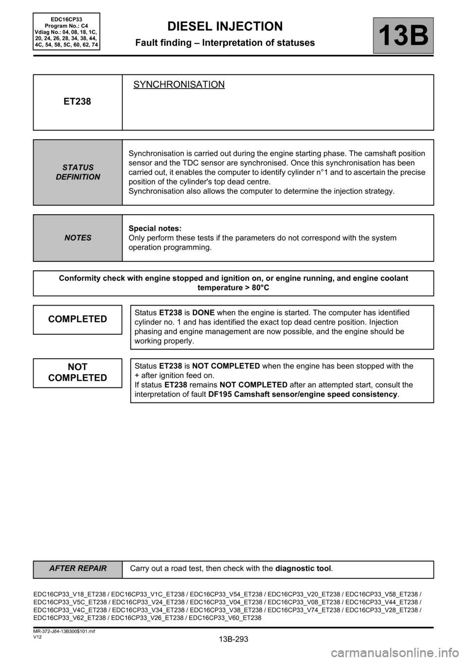
ET238SYNCHRONISATION
STATUS
DEFINITIONSynchronisation is carried out during the engine starting phase. The camshaft position
sensor and the TDC sensor are synchronised. Once this synchronisation has been
carried out, it enables the computer to identify cylinder n°1 and to ascertain the precise
position of the cylinder's top dead centre.
Synchronisation also allows the computer to determine the injection strategy.
NOTESSpecial notes:
Only perform these tests if the parameters do not correspond with the system
operation programming.
Conformity check with engine stopped and ignition on, or engine running, and engine coolant
temperature > 80°C
COMPLETEDStatus ET238 is DONE when the engine is started. The computer has identified
cylinder no. 1 and has identified the exact top dead centre position. Injection
phasing and engine management are now possible, and the engine should be
working properly.
NOT
COMPLETEDStatus ET238 is NOT COMPLETED when the engine has been stopped with the
+ after ignition feed on.
If status ET238 remains NOT COMPLETED after an attempted start, consult the
interpretation of fault DF195 Camshaft sensor/engine speed consistency.
EDC16CP33_V18_ET238 / EDC16CP33_V1C_ET238 / EDC16CP33_V54_ET238 / EDC16CP33_V20_ET238 / EDC16CP33_V58_ET238 /
EDC16CP33_V5C_ET238 / EDC16CP33_V24_ET238 / EDC16CP33_V04_ET238 / EDC16CP33_V08_ET238 / EDC16CP33_V44_ET238 /
EDC16CP33_V4C_ET238 / EDC16CP33_V34_ET238 / EDC16CP33_V38_ET238 / EDC16CP33_V74_ET238 / EDC16CP33_V28_ET238 /
EDC16CP33_V62_ET238 / EDC16CP33_V26_ET238 / EDC16CP33_V60_ET238
AFTER REPAIRCarry out a road test, then check with the diagnostic tool.
EDC16CP33
Program No.: C4
Vdiag No.: 04, 08, 18, 1C,
20, 24, 26, 28, 34, 38, 44,
4C, 54, 58, 5C, 60, 62, 74
Page 294 of 510
13B-294V12 MR-372-J84-13B300$101.mif
DIESEL INJECTION
Fault finding – Interpretation of statuses13B
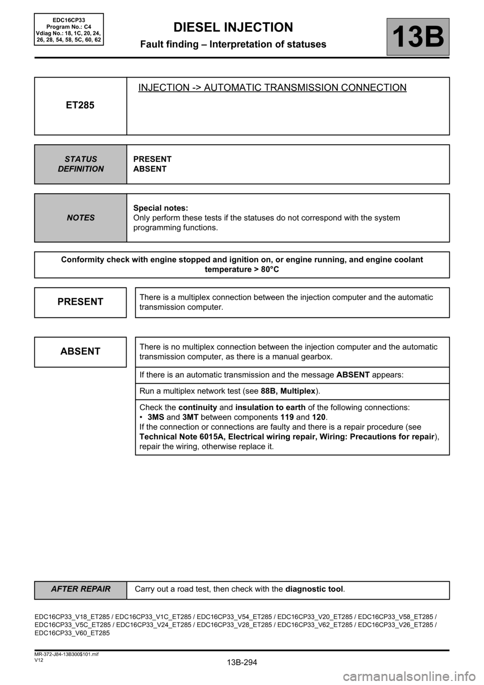
ET285INJECTION -> AUTOMATIC TRANSMISSION CONNECTION
STATUS
DEFINITIONPRESENT
ABSENT
NOTESSpecial notes:
Only perform these tests if the statuses do not correspond with the system
programming functions.
Conformity check with engine stopped and ignition on, or engine running, and engine coolant
temperature > 80°C
PRESENTThere is a multiplex connection between the injection computer and the automatic
transmission computer.
ABSENTThere is no multiplex connection between the injection computer and the automatic
transmission computer, as there is a manual gearbox.
If there is an automatic transmission and the message ABSENT appears:
Run a multiplex network test (see 88B, Multiplex).
Check the continuity and insulation to earth of the following connections:
•3MS and 3MT between components 119 and 120.
If the connection or connections are faulty and there is a repair procedure (see
Technical Note 6015A, Electrical wiring repair, Wiring: Precautions for repair),
repair the wiring, otherwise replace it.
EDC16CP33_V18_ET285 / EDC16CP33_V1C_ET285 / EDC16CP33_V54_ET285 / EDC16CP33_V20_ET285 / EDC16CP33_V58_ET285 /
EDC16CP33_V5C_ET285 / EDC16CP33_V24_ET285 / EDC16CP33_V28_ET285 / EDC16CP33_V62_ET285 / EDC16CP33_V26_ET285 /
EDC16CP33_V60_ET285
AFTER REPAIRCarry out a road test, then check with the diagnostic tool.
EDC16CP33
Program No.: C4
Vdiag No.: 18, 1C, 20, 24,
26, 28, 54, 58, 5C, 60, 62