wiring RENAULT SCENIC 2012 J95 / 3.G Engine And Peripherals EDC16CP33 Owner's Manual
[x] Cancel search | Manufacturer: RENAULT, Model Year: 2012, Model line: SCENIC, Model: RENAULT SCENIC 2012 J95 / 3.GPages: 510, PDF Size: 2.98 MB
Page 48 of 510
13B-48
AFTER REPAIRDeal with any other faults. Clear the fault memory.
Switch off the ignition until the end of the power-latch phase, and carry out a road test
followed by a check with the diagnostic tool.
V12 MR-372-J84-13B300$071.mif
DIESEL INJECTION
Fault finding – Interpretation of faults13B
EDC16CP33
Program No.: C4
Vdiag No.: 04, 08, 18, 1C,
20, 24, 26, 28, 34, 38, 44,
4C, 54, 58, 5C, 60, 62, 74
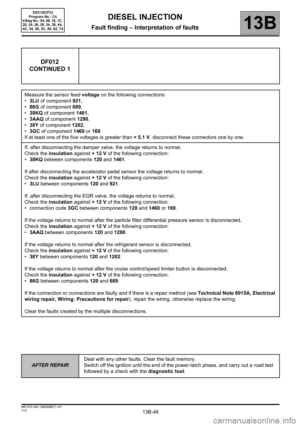
DF012
CONTINUED 1
Measure the sensor feed voltage on the following connections:
•3LU of component 921,
•86G of component 689,
•38KQ of component 1461,
•3AAQ of component 1290,
•38Y of component 1202,
•3GC of component 1460 or 169.
If at least one of the five voltages is greater than + 5.1 V, disconnect these connectors one by one.
If, after disconnecting the damper valve, the voltage returns to normal,
Check the insulation against + 12 V of the following connection:
•38KQ between components 120 and 1461.
If after disconnecting the accelerator pedal sensor the voltage returns to normal,
Check the insulation against + 12 V of the following connection:
•3LU between components 120 and 921.
If, after disconnecting the EGR valve, the voltage returns to normal,
Check the insulation against + 12 V of the following connection:
• connection code 3GC between components 120 and 1460 or 169.
If the voltage returns to normal after the particle filter differential pressure sensor is disconnected,
Check the insulation against + 12 V of the following connection:
•3AAQ between components 120 and 1290.
If the voltage returns to normal after the refrigerant sensor is disconnected,
Check the insulation against + 12 V of the following connection:
•38Y between components 120 and 1202.
If the voltage returns to normal after the cruise control/speed limiter button is disconnected,
Check the insulation against + 12 V of the following connection:
•86G between components 120 and 689.
If the connection or connections are faulty and if there is a repair method (see Technical Note 6015A, Electrical
wiring repair, Wiring: Precautions for repair), repair the wiring, otherwise replace the wiring.
Clear the faults created by the multiple disconnections.
Page 49 of 510
13B-49
AFTER REPAIRDeal with any other faults. Clear the fault memory.
Switch off the ignition until the end of the power-latch phase, and carry out a road test
followed by a check with the diagnostic tool.
V12 MR-372-J84-13B300$071.mif
DIESEL INJECTION
Fault finding – Interpretation of faults13B
EDC16CP33
Program No.: C4
Vdiag No.: 04, 08, 18, 1C,
20, 24, 26, 28, 34, 38, 44,
4C, 54, 58, 5C, 60, 62, 74
DF012
CONTINUED 2
Check the condition of the engine management computer connector (see Wiring Diagram Technical Note,
Laguna II ph2, Vel Satis ph2, Espace IV ph2, Mégane II ph2, Scénic II ph2, component code 120).
If the connector is faulty and there is a repair method (see Technical Note 6015A, Repairing electrical wiring,
Wiring: Precautions for repair), repair the connector, otherwise replace the wiring.
If the fault is still present, contact the Techline.
Page 51 of 510
13B-51
AFTER REPAIRDeal with any other faults. Clear the fault memory.
Switch off the ignition until the end of the power-latch phase, and carry out a road test
followed by a check with the diagnostic tool.
V12 MR-372-J84-13B300$071.mif
DIESEL INJECTION
Fault finding – Interpretation of faults13B
EDC16CP33
Program No.: C4
Vdiag No.: 04, 08, 18, 1C,
20, 24, 26, 28, 34, 38, 44,
4C, 54, 58, 5C, 60, 62, 74
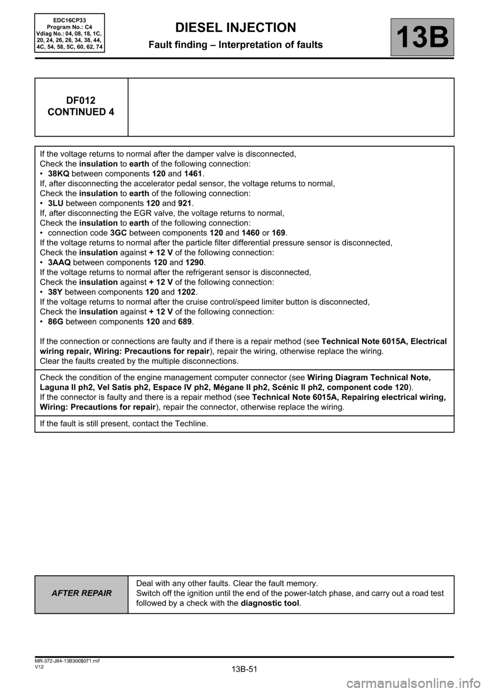
DF012
CONTINUED 4
If the voltage returns to normal after the damper valve is disconnected,
Check the insulation to earth of the following connection:
•38KQ between components 120 and 1461.
If, after disconnecting the accelerator pedal sensor, the voltage returns to normal,
Check the insulation to earth of the following connection:
•3LU between components 120 and 921.
If, after disconnecting the EGR valve, the voltage returns to normal,
Check the insulation to earth of the following connection:
• connection code 3GC between components 120 and 1460 or 169.
If the voltage returns to normal after the particle filter differential pressure sensor is disconnected,
Check the insulation against + 12 V of the following connection:
•3AAQ between components 120 and 1290.
If the voltage returns to normal after the refrigerant sensor is disconnected,
Check the insulation against + 12 V of the following connection:
•38Y between components 120 and 1202.
If the voltage returns to normal after the cruise control/speed limiter button is disconnected,
Check the insulation against + 12 V of the following connection:
•86G between components 120 and 689.
If the connection or connections are faulty and if there is a repair method (see Technical Note 6015A, Electrical
wiring repair, Wiring: Precautions for repair), repair the wiring, otherwise replace the wiring.
Clear the faults created by the multiple disconnections.
Check the condition of the engine management computer connector (see Wiring Diagram Technical Note,
Laguna II ph2, Vel Satis ph2, Espace IV ph2, Mégane II ph2, Scénic II ph2, component code 120).
If the connector is faulty and there is a repair method (see Technical Note 6015A, Repairing electrical wiring,
Wiring: Precautions for repair), repair the connector, otherwise replace the wiring.
If the fault is still present, contact the Techline.
Page 52 of 510
13B-52
AFTER REPAIRDeal with any other faults. Clear the fault memory.
Switch off the ignition until the end of the power-latch phase, and carry out a road test
followed by a check with the diagnostic tool.
V12 MR-372-J84-13B300$071.mif
DIESEL INJECTION
Fault finding – Interpretation of faults13B
EDC16CP33
Program No.: C4
Vdiag No.: 04, 08, 18, 1C,
20, 24, 26, 28, 34, 38, 44,
4C, 54, 58, 5C, 60, 62, 74
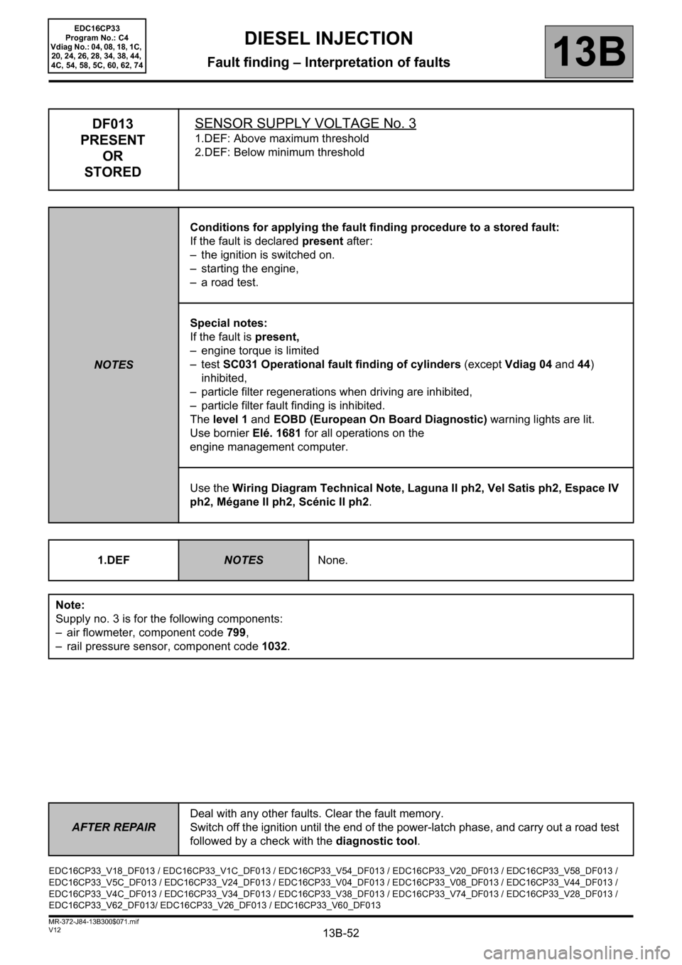
DF013
PRESENT
OR
STOREDSENSOR SUPPLY VOLTAGE No. 3
1.DEF: Above maximum threshold
2.DEF: Below minimum threshold
NOTESConditions for applying the fault finding procedure to a stored fault:
If the fault is declared present after:
– the ignition is switched on.
– starting the engine,
– a road test.
Special notes:
If the fault is present,
– engine torque is limited
–test SC031 Operational fault finding of cylinders (except Vdiag 04 and 44)
inhibited,
– particle filter regenerations when driving are inhibited,
– particle filter fault finding is inhibited.
The level 1 and EOBD (European On Board Diagnostic) warning lights are lit.
Use bornier Elé. 1681 for all operations on the
engine management computer.
Use the Wiring Diagram Technical Note, Laguna II ph2, Vel Satis ph2, Espace IV
ph2, Mégane II ph2, Scénic II ph2.
1.DEF
NOTESNone.
Note:
Supply no. 3 is for the following components:
– air flowmeter, component code 799,
– rail pressure sensor, component code 1032.
EDC16CP33_V18_DF013 / EDC16CP33_V1C_DF013 / EDC16CP33_V54_DF013 / EDC16CP33_V20_DF013 / EDC16CP33_V58_DF013 /
EDC16CP33_V5C_DF013 / EDC16CP33_V24_DF013 / EDC16CP33_V04_DF013 / EDC16CP33_V08_DF013 / EDC16CP33_V44_DF013 /
EDC16CP33_V4C_DF013 / EDC16CP33_V34_DF013 / EDC16CP33_V38_DF013 / EDC16CP33_V74_DF013 / EDC16CP33_V28_DF013 /
EDC16CP33_V62_DF013/ EDC16CP33_V26_DF013 / EDC16CP33_V60_DF013
Page 53 of 510
13B-53
AFTER REPAIRDeal with any other faults. Clear the fault memory.
Switch off the ignition until the end of the power-latch phase, and carry out a road test
followed by a check with the diagnostic tool.
V12 MR-372-J84-13B300$071.mif
DIESEL INJECTION
Fault finding – Interpretation of faults13B
EDC16CP33
Program No.: C4
Vdiag No.: 04, 08, 18, 1C,
20, 24, 26, 28, 34, 38, 44,
4C, 54, 58, 5C, 60, 62, 74
DF013
CONTINUED 1
Measure the sensor feed voltage on the following connections:
•3KJ of component 799,
•3LX of component 1032.
If at least one of the two voltages is greater than + 5.1 V, disconnect the sensor connectors one by one.
If, after disconnecting the air flow sensor, the voltage returns to normal,
Check the insulation against + 12 V of the following connection:
•3KJ between components 120 and 799.
If, after disconnecting the rail pressure sensor, the voltage returns to normal,
Check the insulation from + 12 V of the following connection: 3LX between components 120 and 1032.
If the connection or connections are faulty and if there is a repair method (see Technical Note 6015A, Electrical
wiring repair, Wiring: Precautions for repair), repair the wiring, otherwise replace the wiring.
Clear the faults created by the multiple disconnections.
Check the condition of the engine management computer connector (see Wiring Diagram Technical Note,
Laguna II ph2, Vel Satis ph2, Espace IV ph2, Mégane II ph2, Scénic II ph2, component code 120).
If the connector is faulty and there is a repair method (see Technical Note 6015A, Repairing electrical wiring,
Wiring: Precautions for repair), repair the connector, otherwise replace the wiring.
If the fault is still present, contact the Techline.
Page 54 of 510
13B-54
AFTER REPAIRDeal with any other faults. Clear the fault memory.
Switch off the ignition until the end of the power-latch phase, and carry out a road test
followed by a check with the diagnostic tool.
V12 MR-372-J84-13B300$071.mif
DIESEL INJECTION
Fault finding – Interpretation of faults13B
EDC16CP33
Program No.: C4
Vdiag No.: 04, 08, 18, 1C,
20, 24, 26, 28, 34, 38, 44,
4C, 54, 58, 5C, 60, 62, 74
DF013
CONTINUED 2
2.DEFNOTESNone.
Note:
Supply no. 3 is for the following components:
– air flowmeter, component code 799,
– rail pressure sensor, component code 1032.
Measure the sensor feed voltage on the following connections:
•3KJ of component 799,
•3LX of component 1032.
If at least one of the two voltages is less than 4.9 V, disconnect the sensor connectors one by one.
If, after disconnecting the air flow sensor, the voltage returns to normal,
Check the insulation to earth of the following connection:
•3KJ between components 120 and 799.
If, after disconnecting the rail pressure sensor, the voltage returns to normal,
Check the insulation to earth of the following connection:
•3LX between components 120 and 1032.
If the connection or connections are faulty and if there is a repair method (see Technical Note 6015A, Electrical
wiring repair, Wiring: Precautions for repair), repair the wiring, otherwise replace the wiring.
Clear the faults created by the multiple disconnections.
Check the condition of the engine management computer connector (see Wiring Diagram Technical Note,
Laguna II ph2, Vel Satis ph2, Espace IV ph2, Mégane II ph2, Scénic II ph2, component code 120).
If the connector is faulty and there is a repair method (see Technical Note 6015A, Repairing electrical wiring,
Wiring: Precautions for repair), repair the connector, otherwise replace the wiring.
If the fault is still present, contact the Techline.
Page 55 of 510
13B-55
AFTER REPAIRDeal with any other faults. Clear the fault memory.
Switch off the ignition until the end of the power-latch phase, and carry out a road test
followed by a check with the diagnostic tool.
V12 MR-372-J84-13B300$071.mif
DIESEL INJECTION
Fault finding – Interpretation of faults13B
EDC16CP33
Program No.: C4
Vdiag No.: 04, 08, 18, 1C,
20, 24, 26, 28, 34, 38, 44,
4C, 54, 58, 5C, 60, 62, 74
DF017
PRESENT
OR
STOREDPRE-POSTHEATING UNIT CONTROL CIRCUITCO: Open circuit
CC.1: Short circuit to + 12 V
CC.0: Short circuit to earth
1.DEF: Internal electronic fault
NOTESConditions for applying the fault finding procedure to a stored fault:
If DF025 Preheating unit diagnostic line is present, disregard it.
If the fault is declared present after:
– the ignition is switched on.
– starting the engine,
– a road test,
– relay actuation using command AC037 Preheating relay.
Special notes:
– preheating inhibited.
Use bornier Elé. 1681 for all operations on the engine management computer
connectors.
Use the Wiring Diagram Technical Note, Laguna II ph2, Vel Satis ph2, Espace IV
ph2, Mégane II ph2, Scénic II ph2.
CO
NOTESNone.
Check the condition of the preheating unit connector (see Wiring Diagram Technical Note, Laguna II ph2, Vel
Satis ph2, Espace IV ph2, Mégane II ph2, Scénic II ph2, component code 257).
Check the condition of the engine management computer connector (see Wiring Diagram Technical Note,
Laguna II ph2, Vel Satis ph2, Espace IV ph2, Mégane II ph2, Scénic II ph2, component code 120).
If the connector or connectors are faulty and if there is a repair procedure (see Technical Note 6015A, Electrical
wiring repair, Wiring: Precautions for repair), repair the connector, otherwise replace the wiring.
Measure the resistance between connections 3FF and BP35 of component 257.
If the resistance is greater than 2 kΩ, replace the preheating unit.
EDC16CP33_V18_DF017 / EDC16CP33_V1C_DF017 / EDC16CP33_V54_DF017 / EDC16CP33_V20_DF017 / EDC16CP33_V58_DF017 /
EDC16CP33_V5C_DF017 / EDC16CP33_V24_DF017 / EDC16CP33_V04_DF017 / EDC16CP33_V08_DF017 / EDC16CP33_V44_DF017 /
EDC16CP33_V4C_DF017 / EDC16CP33_V34_DF017 / EDC16CP33_V38_DF017 / EDC16CP33_V74_DF017 / EDC16CP33_V28_DF017 /
EDC16CP33_V62_DF017/ EDC16CP33_V26_DF017 / EDC16CP33_V60_DF017
Page 56 of 510
13B-56
AFTER REPAIRDeal with any other faults. Clear the fault memory.
Switch off the ignition until the end of the power-latch phase, and carry out a road test
followed by a check with the diagnostic tool.
V12 MR-372-J84-13B300$071.mif
DIESEL INJECTION
Fault finding – Interpretation of faults13B
EDC16CP33
Program No.: C4
Vdiag No.: 04, 08, 18, 1C,
20, 24, 26, 28, 34, 38, 44,
4C, 54, 58, 5C, 60, 62, 74
DF017
CONTINUED 1
Check the continuity of the following connection:
•3FF between components 120 and 257.
Check the + 12 V battery supply to the preheating unit on the following connection:
•BP35 of component 257.
If the connection or connections are faulty and if there is a repair method (see Technical Note 6015A, Electrical
wiring repair, Wiring: Precautions for repair), repair the wiring, otherwise replace the wiring.
If the fault is still present, replace the pre-postheating unit.
CC.1
NOTESNone.
Check the condition of the preheating unit connector (see Wiring Diagram Technical Note, Laguna II ph2, Vel
Satis ph2, Espace IV ph2, Mégane II ph2, Scénic II ph2, component code 257).
Check the condition of the engine management computer connector (see Wiring Diagram Technical Note,
Laguna II ph2, Vel Satis ph2, Espace IV ph2, Mégane II ph2, Scénic II ph2, component code 120).
If the connector or connectors are faulty and if there is a repair procedure (see Technical Note 6015A, Repairing
electrical wiring, Wiring: Precautions for repair), repair the connector, otherwise replace the wiring.
Measure the resistance between connections 3FF and BP35 of component 257.
If the resistance is less than 1 kΩ, replace the preheating unit.
Check the insulation in relation to +12 V of the following connection:
•3FF between components 120 and 257.
If the connection is faulty and there is a repair procedure (see Technical Note 6015A, Electrical wiring repair,
Wiring: Precautions for repair), repair the wiring, otherwise replace it.
If the fault is still present, replace the pre-postheating unit.
Page 57 of 510
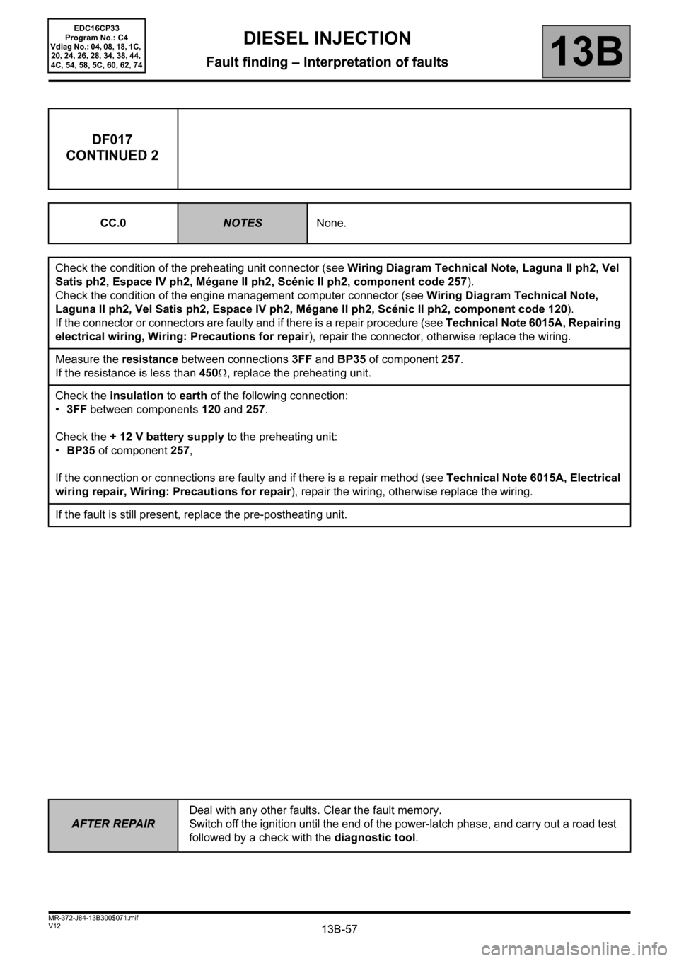
13B-57
AFTER REPAIRDeal with any other faults. Clear the fault memory.
Switch off the ignition until the end of the power-latch phase, and carry out a road test
followed by a check with the diagnostic tool.
V12 MR-372-J84-13B300$071.mif
DIESEL INJECTION
Fault finding – Interpretation of faults13B
EDC16CP33
Program No.: C4
Vdiag No.: 04, 08, 18, 1C,
20, 24, 26, 28, 34, 38, 44,
4C, 54, 58, 5C, 60, 62, 74
DF017
CONTINUED 2
CC.0NOTESNone.
Check the condition of the preheating unit connector (see Wiring Diagram Technical Note, Laguna II ph2, Vel
Satis ph2, Espace IV ph2, Mégane II ph2, Scénic II ph2, component code 257).
Check the condition of the engine management computer connector (see Wiring Diagram Technical Note,
Laguna II ph2, Vel Satis ph2, Espace IV ph2, Mégane II ph2, Scénic II ph2, component code 120).
If the connector or connectors are faulty and if there is a repair procedure (see Technical Note 6015A, Repairing
electrical wiring, Wiring: Precautions for repair), repair the connector, otherwise replace the wiring.
Measure the resistance between connections 3FF and BP35 of component 257.
If the resistance is less than 450Ω, replace the preheating unit.
Check the insulation to earth of the following connection:
•3FF between components 120 and 257.
Check the + 12 V battery supply to the preheating unit:
•BP35 of component 257,
If the connection or connections are faulty and if there is a repair method (see Technical Note 6015A, Electrical
wiring repair, Wiring: Precautions for repair), repair the wiring, otherwise replace the wiring.
If the fault is still present, replace the pre-postheating unit.
Page 58 of 510
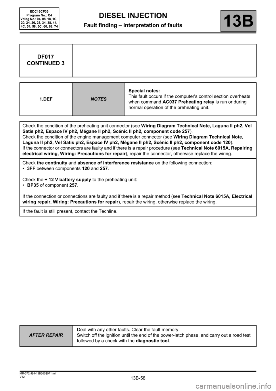
13B-58
AFTER REPAIRDeal with any other faults. Clear the fault memory.
Switch off the ignition until the end of the power-latch phase, and carry out a road test
followed by a check with the diagnostic tool.
V12 MR-372-J84-13B300$071.mif
DIESEL INJECTION
Fault finding – Interpretation of faults13B
EDC16CP33
Program No.: C4
Vdiag No.: 04, 08, 18, 1C,
20, 24, 26, 28, 34, 38, 44,
4C, 54, 58, 5C, 60, 62, 74
DF017
CONTINUED 3
1.DEFNOTESSpecial notes:
This fault occurs if the computer's control section overheats
when command AC037 Preheating relay is run or during
normal operation of the preheating unit.
Check the condition of the preheating unit connector (see Wiring Diagram Technical Note, Laguna II ph2, Vel
Satis ph2, Espace IV ph2, Mégane II ph2, Scénic II ph2, component code 257).
Check the condition of the engine management computer connector (see Wiring Diagram Technical Note,
Laguna II ph2, Vel Satis ph2, Espace IV ph2, Mégane II ph2, Scénic II ph2, component code 120).
If the connector or connectors are faulty and if there is a repair procedure (see Technical Note 6015A, Repairing
electrical wiring, Wiring: Precautions for repair), repair the connector, otherwise replace the wiring.
Check the continuity and absence of interference resistance on the following connection:
•3FF between components120 and 257.
Check the + 12 V battery supply to the preheating unit:
•BP35 of component 257.
If the connection or connections are faulty and if there is a repair method (see Technical Note 6015A, Electrical
wiring repair, Wiring: Precautions for repair), repair the wiring, otherwise replace the wiring.
If the fault is still present, contact the Techline.