engine RENAULT SCENIC 2012 J95 / 3.G Engine And Peripherals EDC16CP33 Workshop Manual
[x] Cancel search | Manufacturer: RENAULT, Model Year: 2012, Model line: SCENIC, Model: RENAULT SCENIC 2012 J95 / 3.GPages: 510, PDF Size: 2.98 MB
Page 479 of 510
13B-479
AFTER REPAIRCarry out a road test, then check with the diagnostic tool.
V12 MR-372-J84-13B300$170.mif
DIESEL INJECTION
Fault finding – Fault Finding Chart13B
ALP4
CONTINUED 3
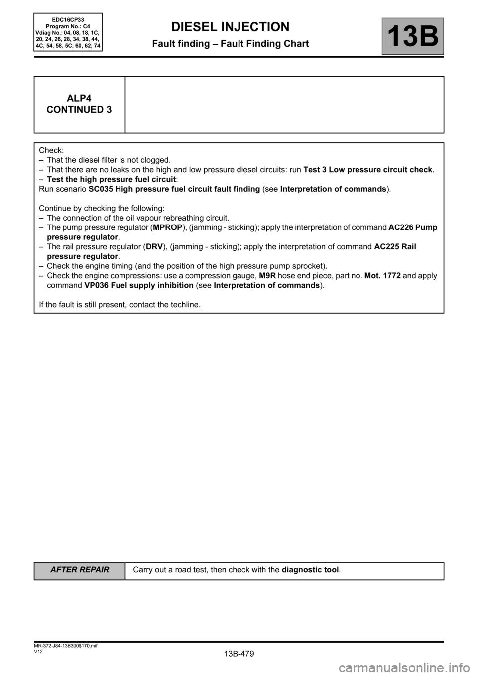
Check:
– That the diesel filter is not clogged.
– That there are no leaks on the high and low pressure diesel circuits: run Test 3 Low pressure circuit check.
–Test the high pressure fuel circuit:
Run scenario SC035 High pressure fuel circuit fault finding (see Interpretation of commands).
Continue by checking the following:
– The connection of the oil vapour rebreathing circuit.
– The pump pressure regulator (MPROP), (jamming - sticking); apply the interpretation of command AC226 Pump
pressure regulator.
– The rail pressure regulator (DRV), (jamming - sticking); apply the interpretation of command AC225 Rail
pressure regulator.
– Check the engine timing (and the position of the high pressure pump sprocket).
– Check the engine compressions: use a compression gauge, M9R hose end piece, part no. Mot. 1772 and apply
command VP036 Fuel supply inhibition (see Interpretation of commands).
If the fault is still present, contact the techline.
EDC16CP33
Program No.: C4
Vdiag No.: 04, 08, 18, 1C,
20, 24, 26, 28, 34, 38, 44,
4C, 54, 58, 5C, 60, 62, 74
Page 480 of 510
13B-480
AFTER REPAIRCarry out a road test, then check with the diagnostic tool.
V12 MR-372-J84-13B300$170.mif
DIESEL INJECTION
Fault finding – Fault Finding Chart13B
ALP5 Irregular engine operation
NOTESBefore analysing this customer complaint, check that there are no faults, and the
conformity (or otherwise) of the parameters and statuses, using the diagnostic tool.
If the customer complaint is not eliminated, perform the following checks.
Use the Wiring Diagram Technical Note, Laguna II ph2, Vel Satis ph2, Espace IV
ph2, Mégane II ph2, Scénic II ph2.
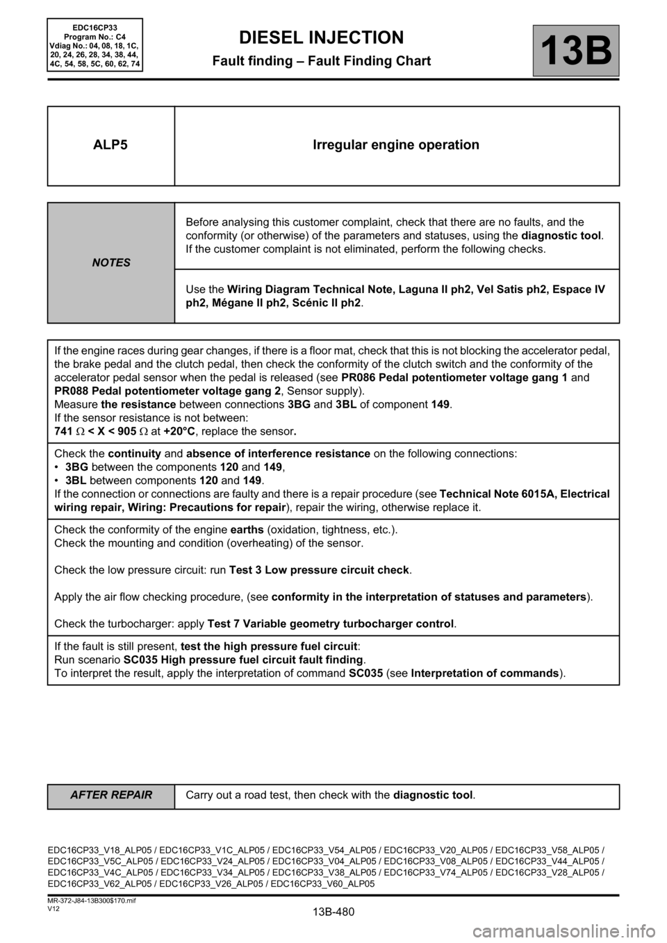
If the engine races during gear changes, if there is a floor mat, check that this is not blocking the accelerator pedal,
the brake pedal and the clutch pedal, then check the conformity of the clutch switch and the conformity of the
accelerator pedal sensor when the pedal is released (see PR086 Pedal potentiometer voltage gang 1 and
PR088 Pedal potentiometer voltage gang 2, Sensor supply).
Measure the resistance between connections 3BG and 3BL of component 149.
If the sensor resistance is not between:
741 Ω < X < 905 Ω at +20°C, replace the sensor.
Check the continuity and absence of interference resistance on the following connections:
•3BG between the components 120 and 149,
•3BL between components 120 and 149.
If the connection or connections are faulty and there is a repair procedure (see Technical Note 6015A, Electrical
wiring repair, Wiring: Precautions for repair), repair the wiring, otherwise replace it.
Check the conformity of the engine earths (oxidation, tightness, etc.).
Check the mounting and condition (overheating) of the sensor.
Check the low pressure circuit: run Test 3 Low pressure circuit check.
Apply the air flow checking procedure, (see conformity in the interpretation of statuses and parameters).
Check the turbocharger: apply Test 7 Variable geometry turbocharger control.
If the fault is still present, test the high pressure fuel circuit:
Run scenario SC035 High pressure fuel circuit fault finding.
To interpret the result, apply the interpretation of command SC035 (see Interpretation of commands).
EDC16CP33_V18_ALP05 / EDC16CP33_V1C_ALP05 / EDC16CP33_V54_ALP05 / EDC16CP33_V20_ALP05 / EDC16CP33_V58_ALP05 /
EDC16CP33_V5C_ALP05 / EDC16CP33_V24_ALP05 / EDC16CP33_V04_ALP05 / EDC16CP33_V08_ALP05 / EDC16CP33_V44_ALP05 /
EDC16CP33_V4C_ALP05 / EDC16CP33_V34_ALP05 / EDC16CP33_V38_ALP05 / EDC16CP33_V74_ALP05 / EDC16CP33_V28_ALP05 /
EDC16CP33_V62_ALP05 / EDC16CP33_V26_ALP05 / EDC16CP33_V60_ALP05
EDC16CP33
Program No.: C4
Vdiag No.: 04, 08, 18, 1C,
20, 24, 26, 28, 34, 38, 44,
4C, 54, 58, 5C, 60, 62, 74
Page 481 of 510
13B-481
AFTER REPAIRCarry out a road test, then check with the diagnostic tool.
V12 MR-372-J84-13B300$170.mif
DIESEL INJECTION
Fault finding – Fault Finding Chart13B
ALP6 Fuel system leaks
NOTESBefore analysing this customer complaint, check that there are no faults, and the
conformity (or otherwise) of the parameters and statuses, using the diagnostic tool.
If the customer complaint is not eliminated, perform the following checks.
IMPORTANT:
Please observe the cleanliness guidelines and safety advice.
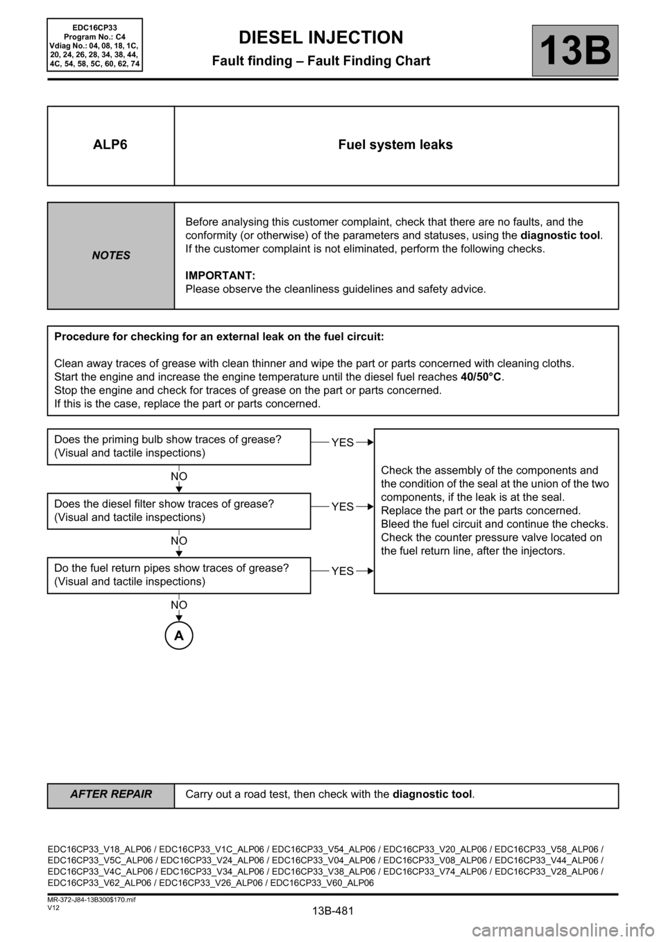
Procedure for checking for an external leak on the fuel circuit:
Clean away traces of grease with clean thinner and wipe the part or parts concerned with cleaning cloths.
Start the engine and increase the engine temperature until the diesel fuel reaches 40/50°C.
Stop the engine and check for traces of grease on the part or parts concerned.
If this is the case, replace the part or parts concerned.
Does the priming bulb show traces of grease?
(Visual and tactile inspections)
Check the assembly of the components and
the condition of the seal at the union of the two
components, if the leak is at the seal.
Replace the part or the parts concerned.
Bleed the fuel circuit and continue the checks.
Check the counter pressure valve located on
the fuel return line, after the injectors. Does the diesel filter show traces of grease?
(Visual and tactile inspections)
Do the fuel return pipes show traces of grease?
(Visual and tactile inspections)
YES
NO
YES
NO
YES
NO
A
EDC16CP33_V18_ALP06 / EDC16CP33_V1C_ALP06 / EDC16CP33_V54_ALP06 / EDC16CP33_V20_ALP06 / EDC16CP33_V58_ALP06 /
EDC16CP33_V5C_ALP06 / EDC16CP33_V24_ALP06 / EDC16CP33_V04_ALP06 / EDC16CP33_V08_ALP06 / EDC16CP33_V44_ALP06 /
EDC16CP33_V4C_ALP06 / EDC16CP33_V34_ALP06 / EDC16CP33_V38_ALP06 / EDC16CP33_V74_ALP06 / EDC16CP33_V28_ALP06 /
EDC16CP33_V62_ALP06 / EDC16CP33_V26_ALP06 / EDC16CP33_V60_ALP06
EDC16CP33
Program No.: C4
Vdiag No.: 04, 08, 18, 1C,
20, 24, 26, 28, 34, 38, 44,
4C, 54, 58, 5C, 60, 62, 74
Page 484 of 510
13B-484
AFTER REPAIRCarry out a road test, then check with the diagnostic tool.
V12 MR-372-J84-13B300$170.mif
DIESEL INJECTION
Fault finding – Fault Finding Chart13B
ALP7 Rough idle
NOTESBefore analysing this customer complaint, check that there are no faults, and the
conformity (or otherwise) of the parameters and statuses, using the diagnostic tool.
If the customer complaint is not eliminated, perform the following checks.
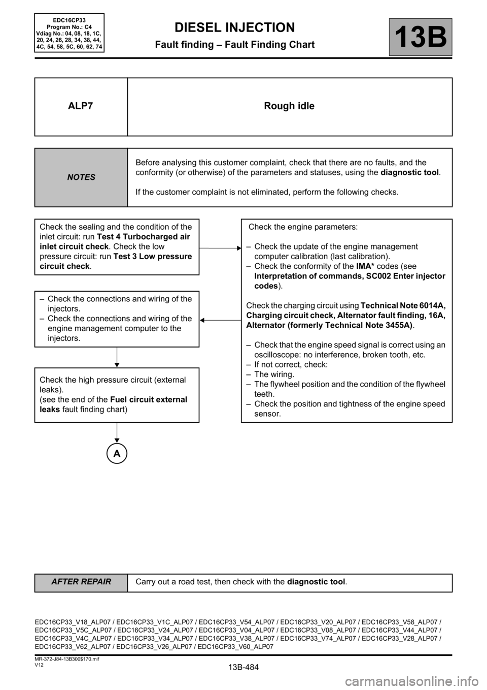
Check the sealing and the condition of the
inlet circuit: run Test 4 Turbocharged air
inlet circuit check. Check the low
pressure circuit: run Test 3 Low pressure
circuit check. Check the engine parameters:
– Check the update of the engine management
computer calibration (last calibration).
– Check the conformity of the IMA* codes (see
Interpretation of commands, SC002 Enter injector
codes).
Check the charging circuit using Technical Note 6014A,
Charging circuit check, Alternator fault finding, 16A,
Alternator (formerly Technical Note 3455A).
– Check that the engine speed signal is correct using an
oscilloscope: no interference, broken tooth, etc.
– If not correct, check:
– The wiring.
– The flywheel position and the condition of the flywheel
teeth.
– Check the position and tightness of the engine speed
sensor. – Check the connections and wiring of the
injectors.
– Check the connections and wiring of the
engine management computer to the
injectors.
Check the high pressure circuit (external
leaks).
(see the end of the Fuel circuit external
leaks fault finding chart)
A
EDC16CP33_V18_ALP07 / EDC16CP33_V1C_ALP07 / EDC16CP33_V54_ALP07 / EDC16CP33_V20_ALP07 / EDC16CP33_V58_ALP07 /
EDC16CP33_V5C_ALP07 / EDC16CP33_V24_ALP07 / EDC16CP33_V04_ALP07 / EDC16CP33_V08_ALP07 / EDC16CP33_V44_ALP07 /
EDC16CP33_V4C_ALP07 / EDC16CP33_V34_ALP07 / EDC16CP33_V38_ALP07 / EDC16CP33_V74_ALP07 / EDC16CP33_V28_ALP07 /
EDC16CP33_V62_ALP07 / EDC16CP33_V26_ALP07 / EDC16CP33_V60_ALP07
EDC16CP33
Program No.: C4
Vdiag No.: 04, 08, 18, 1C,
20, 24, 26, 28, 34, 38, 44,
4C, 54, 58, 5C, 60, 62, 74
Page 485 of 510
13B-485
AFTER REPAIRCarry out a road test, then check with the diagnostic tool.
V12 MR-372-J84-13B300$170.mif
DIESEL INJECTION
Fault finding – Fault Finding Chart13B
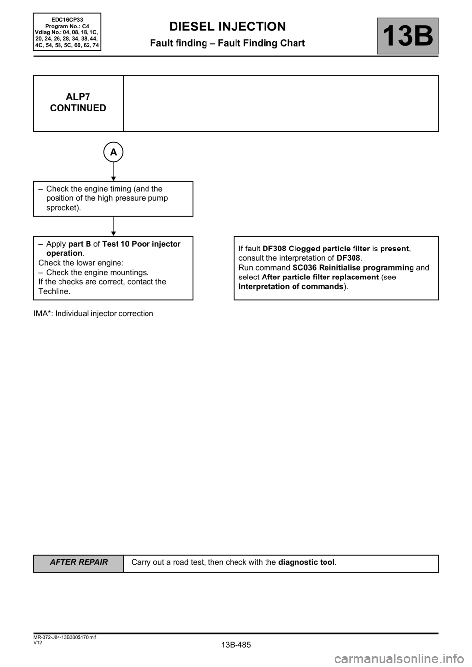
IMA*: Individual injector correction
ALP7
CONTINUED
– Check the engine timing (and the
position of the high pressure pump
sprocket).
–Apply part B of Test 10 Poor injector
operation.
Check the lower engine:
– Check the engine mountings.
If the checks are correct, contact the
Techline.If fault DF308 Clogged particle filter is present,
consult the interpretation of DF308.
Run command SC036 Reinitialise programming and
select After particle filter replacement (see
Interpretation of commands).
A
EDC16CP33
Program No.: C4
Vdiag No.: 04, 08, 18, 1C,
20, 24, 26, 28, 34, 38, 44,
4C, 54, 58, 5C, 60, 62, 74
Page 486 of 510
13B-486
AFTER REPAIRCarry out a road test, then check with the diagnostic tool.
V12 MR-372-J84-13B300$170.mif
DIESEL INJECTION
Fault finding – Fault Finding Chart13B
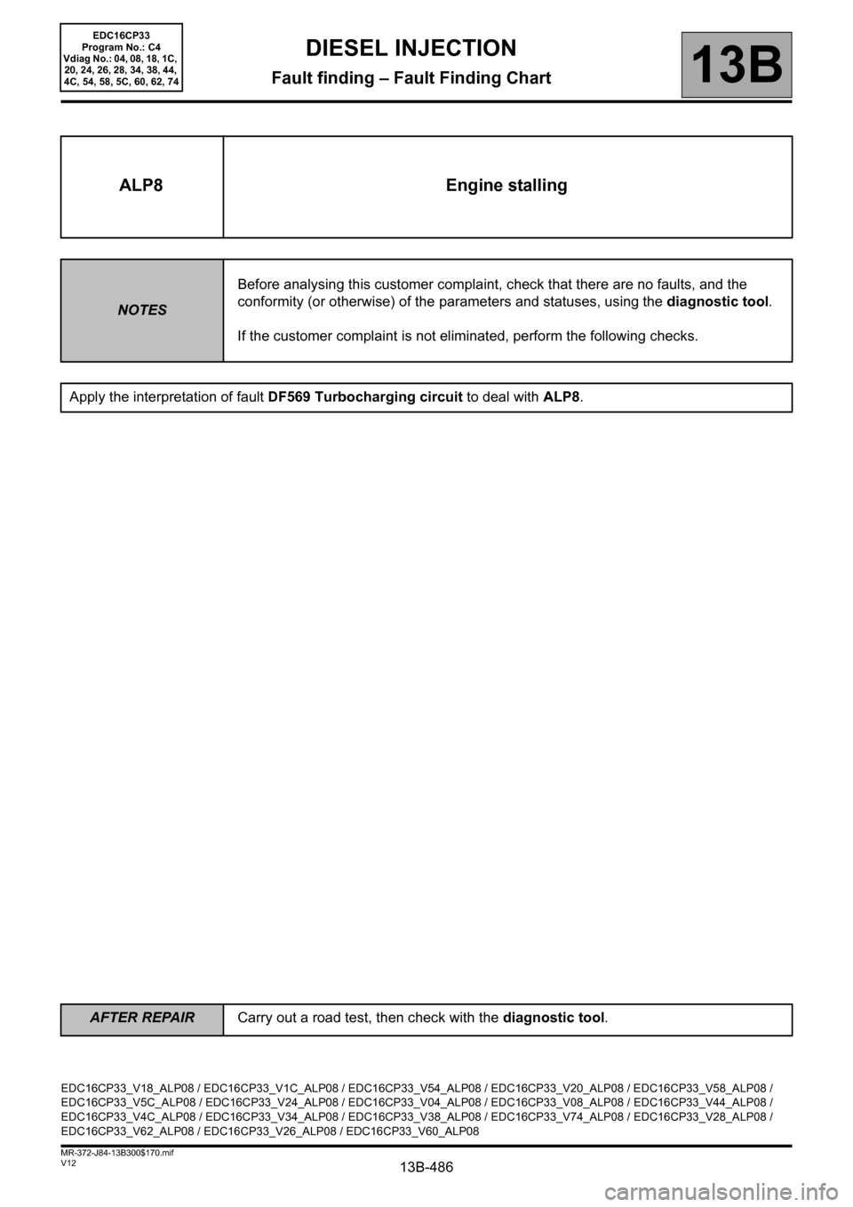
ALP8 Engine stalling
NOTESBefore analysing this customer complaint, check that there are no faults, and the
conformity (or otherwise) of the parameters and statuses, using the diagnostic tool.
If the customer complaint is not eliminated, perform the following checks.
Apply the interpretation of fault DF569 Turbocharging circuit to deal with ALP8.
EDC16CP33_V18_ALP08 / EDC16CP33_V1C_ALP08 / EDC16CP33_V54_ALP08 / EDC16CP33_V20_ALP08 / EDC16CP33_V58_ALP08 /
EDC16CP33_V5C_ALP08 / EDC16CP33_V24_ALP08 / EDC16CP33_V04_ALP08 / EDC16CP33_V08_ALP08 / EDC16CP33_V44_ALP08 /
EDC16CP33_V4C_ALP08 / EDC16CP33_V34_ALP08 / EDC16CP33_V38_ALP08 / EDC16CP33_V74_ALP08 / EDC16CP33_V28_ALP08 /
EDC16CP33_V62_ALP08 / EDC16CP33_V26_ALP08 / EDC16CP33_V60_ALP08
EDC16CP33
Program No.: C4
Vdiag No.: 04, 08, 18, 1C,
20, 24, 26, 28, 34, 38, 44,
4C, 54, 58, 5C, 60, 62, 74
Page 487 of 510
13B-487
AFTER REPAIRCarry out a road test, then check with the diagnostic tool.
V12 MR-372-J84-13B300$170.mif
DIESEL INJECTION
Fault finding – Fault Finding Chart13B
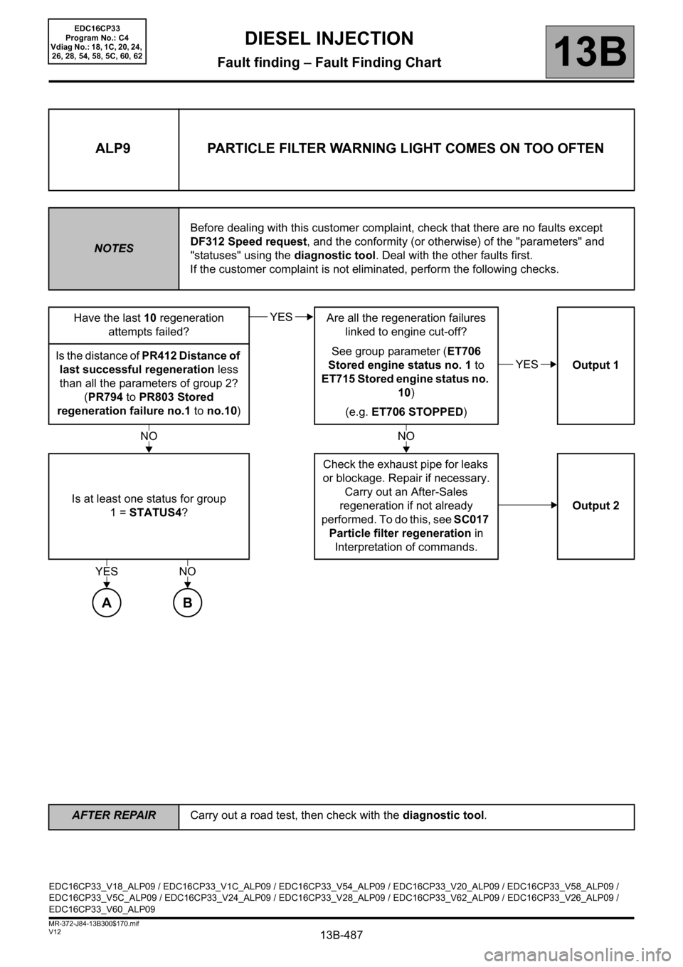
ALP9 PARTICLE FILTER WARNING LIGHT COMES ON TOO OFTEN
NOTESBefore dealing with this customer complaint, check that there are no faults except
DF312 Speed request, and the conformity (or otherwise) of the "parameters" and
"statuses" using the diagnostic tool. Deal with the other faults first.
If the customer complaint is not eliminated, perform the following checks.
Have the last 10 regeneration
attempts failed?Are all the regeneration failures
linked to engine cut-off?
See group parameter (ET706
Stored engine status no. 1 to
ET715 Stored engine status no.
10)
(e.g. ET706 STOPPED)Output 1 Is the distance of PR412 Distance of
last successful regeneration less
than all the parameters of group 2?
(PR794 to PR803 Stored
regeneration failure no.1 to no.10)
Is at least one status for group
1 = STATUS4?Check the exhaust pipe for leaks
or blockage. Repair if necessary.
Carry out an After-Sales
regeneration if not already
performed. To do this, see SC017
Particle filter regeneration in
Interpretation of commands.Output 2
YES
YES
NONO
YES
A
NO
B
EDC16CP33_V18_ALP09 / EDC16CP33_V1C_ALP09 / EDC16CP33_V54_ALP09 / EDC16CP33_V20_ALP09 / EDC16CP33_V58_ALP09 /
EDC16CP33_V5C_ALP09 / EDC16CP33_V24_ALP09 / EDC16CP33_V28_ALP09 / EDC16CP33_V62_ALP09 / EDC16CP33_V26_ALP09 /
EDC16CP33_V60_ALP09
EDC16CP33
Program No.: C4
Vdiag No.: 18, 1C, 20, 24,
26, 28, 54, 58, 5C, 60, 62
Page 491 of 510
13B-491
AFTER REPAIRCarry out a road test, then check with the diagnostic tool.
V12 MR-372-J84-13B300$170.mif
DIESEL INJECTION
Fault finding – Fault Finding Chart13B
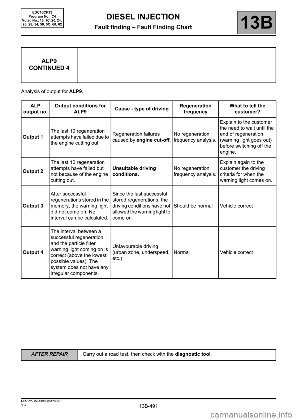
Analysis of output for ALP9.
ALP9
CONTINUED 4
ALP
output no.Output conditions for
ALP9Cause - type of drivingRegeneration
frequencyWhat to tell the
customer?
Output 1The last 10 regeneration
attempts have failed due to
the engine cutting out.Regeneration failures
caused by engine cut-off.No regeneration
frequency analysis.Explain to the customer
the need to wait until the
end of regeneration
(warning light goes out)
before switching off the
engine.
Output 2The last 10 regeneration
attempts have failed but
not because of the engine
cutting out.Unsuitable driving
conditions.No regeneration
frequency analysis.Explain again to the
customer the driving
criteria for when the
warning light comes on.
Output 3After successful
regenerations stored in the
memory, the warning light
did not come on. No
interval can be calculated.Since the last successful
stored regenerations, the
driving conditions have not
allowed the warning light to
come on.Should be normal Vehicle correct
Output 4The interval between a
successful regeneration
and the particle filter
warning light coming on is
correct (above the lowest
possible values). The
system does not have any
irregular components.Unfavourable driving
(urban zone, underspeed,
etc.)Normal Vehicle correct
EDC16CP33
Program No.: C4
Vdiag No.: 18, 1C, 20, 24,
26, 28, 54, 58, 5C, 60, 62
Page 492 of 510
13B-492V12 MR-372-J84-13B300$180.mif
13B
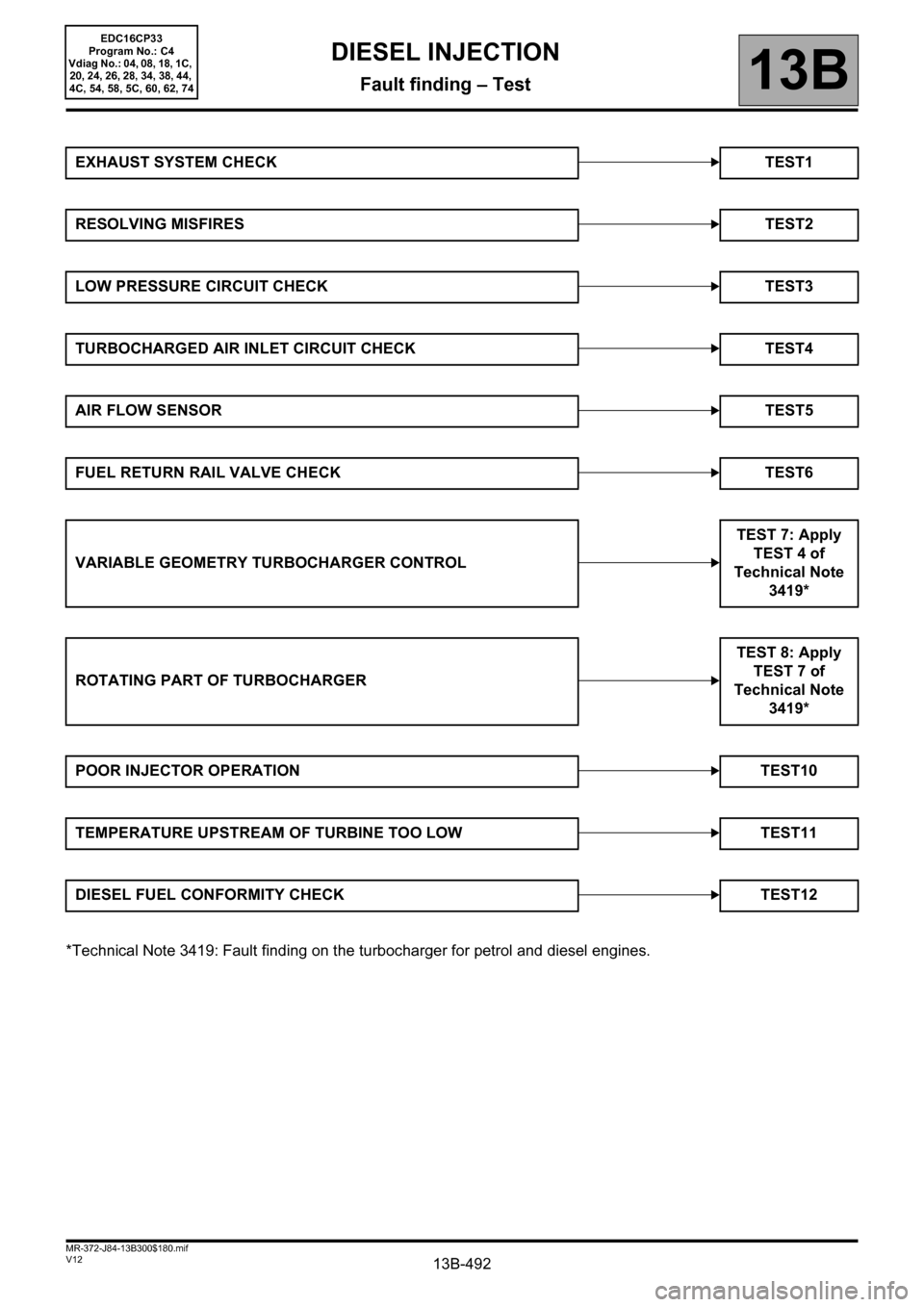
*Technical Note 3419: Fault finding on the turbocharger for petrol and diesel engines. EXHAUST SYSTEM CHECK TEST1
RESOLVING MISFIRESTEST2
LOW PRESSURE CIRCUIT CHECK TEST3
TURBOCHARGED AIR INLET CIRCUIT CHECK TEST4
AIR FLOW SENSORTEST5
FUEL RETURN RAIL VALVE CHECK TEST6
VARIABLE GEOMETRY TURBOCHARGER CONTROLTEST 7: Apply
TEST 4 of
Technical Note
3419*
ROTATING PART OF TURBOCHARGERTEST 8: Apply
TEST 7 of
Technical Note
3419*
POOR INJECTOR OPERATION TEST10
TEMPERATURE UPSTREAM OF TURBINE TOO LOW TEST11
DIESEL FUEL CONFORMITY CHECK TEST12
DIESEL INJECTION
Fault finding – Test
EDC16CP33
Program No.: C4
Vdiag No.: 04, 08, 18, 1C,
20, 24, 26, 28, 34, 38, 44,
4C, 54, 58, 5C, 60, 62, 74
Page 493 of 510
13B-493V12 MR-372-J84-13B300$180.mif
DIESEL INJECTION
Fault finding – Test13B
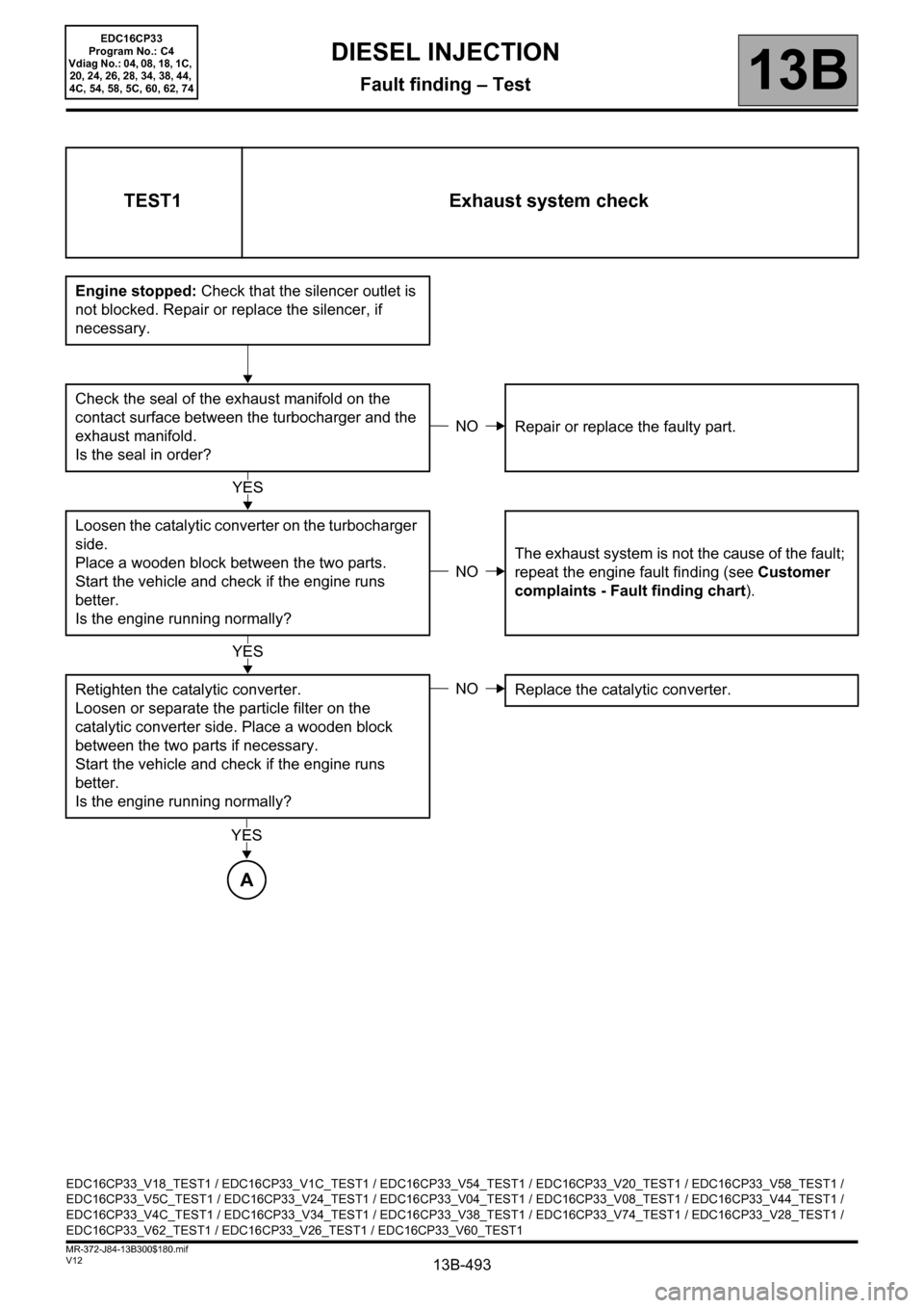
TEST1 Exhaust system check
Engine stopped: Check that the silencer outlet is
not blocked. Repair or replace the silencer, if
necessary.
Check the seal of the exhaust manifold on the
contact surface between the turbocharger and the
exhaust manifold.
Is the seal in order?Repair or replace the faulty part.
Loosen the catalytic converter on the turbocharger
side.
Place a wooden block between the two parts.
Start the vehicle and check if the engine runs
better.
Is the engine running normally?The exhaust system is not the cause of the fault;
repeat the engine fault finding (see Customer
complaints - Fault finding chart).
Retighten the catalytic converter.
Loosen or separate the particle filter on the
catalytic converter side. Place a wooden block
between the two parts if necessary.
Start the vehicle and check if the engine runs
better.
Is the engine running normally?Replace the catalytic converter.
NO
YES
NO
YES
NO
YES
A
EDC16CP33_V18_TEST1 / EDC16CP33_V1C_TEST1 / EDC16CP33_V54_TEST1 / EDC16CP33_V20_TEST1 / EDC16CP33_V58_TEST1 /
EDC16CP33_V5C_TEST1 / EDC16CP33_V24_TEST1 / EDC16CP33_V04_TEST1 / EDC16CP33_V08_TEST1 / EDC16CP33_V44_TEST1 /
EDC16CP33_V4C_TEST1 / EDC16CP33_V34_TEST1 / EDC16CP33_V38_TEST1 / EDC16CP33_V74_TEST1 / EDC16CP33_V28_TEST1 /
EDC16CP33_V62_TEST1 / EDC16CP33_V26_TEST1 / EDC16CP33_V60_TEST1
EDC16CP33
Program No.: C4
Vdiag No.: 04, 08, 18, 1C,
20, 24, 26, 28, 34, 38, 44,
4C, 54, 58, 5C, 60, 62, 74