fuel RENAULT SCENIC 2012 J95 / 3.G Engine And Peripherals EDC16CP33 Service Manual
[x] Cancel search | Manufacturer: RENAULT, Model Year: 2012, Model line: SCENIC, Model: RENAULT SCENIC 2012 J95 / 3.GPages: 510, PDF Size: 2.98 MB
Page 432 of 510
13B-432V12 MR-372-J84-13B300$150.mif
DIESEL INJECTION
Fault finding – Interpretation of commands13B
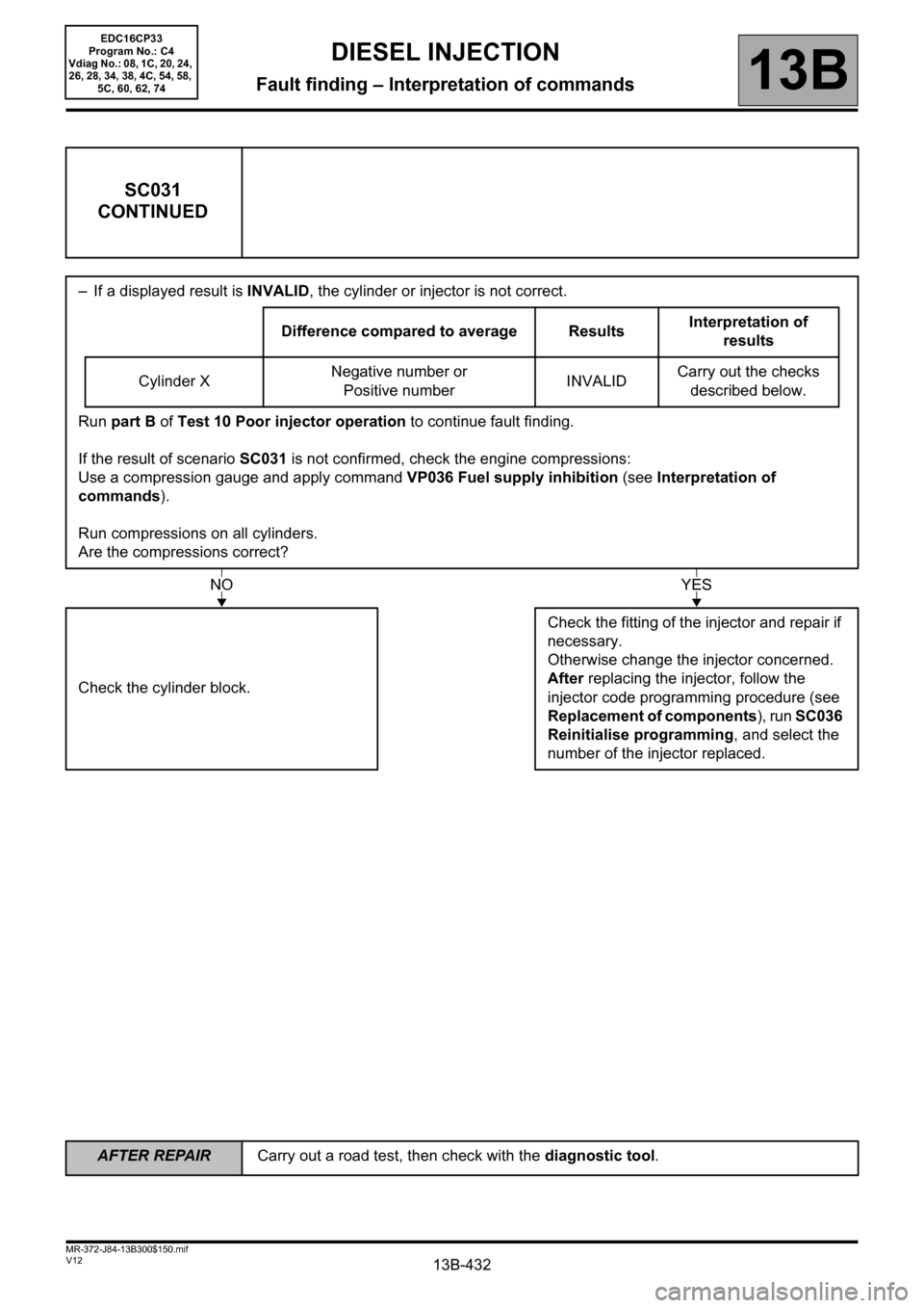
SC031
CONTINUED
– If a displayed result is INVALID, the cylinder or injector is not correct.
Difference compared to average ResultsInterpretation of
results
Cylinder XNegative number or
Positive numberINVALIDCarry out the checks
described below.
Run part B of Test 10 Poor injector operation to continue fault finding.
If the result of scenario SC031 is not confirmed, check the engine compressions:
Use a compression gauge and apply command VP036 Fuel supply inhibition (see Interpretation of
commands).
Run compressions on all cylinders.
Are the compressions correct?
Check the cylinder block.Check the fitting of the injector and repair if
necessary.
Otherwise change the injector concerned.
After replacing the injector, follow the
injector code programming procedure (see
Replacement of components), run SC036
Reinitialise programming, and select the
number of the injector replaced.
NOYES
EDC16CP33
Program No.: C4
Vdiag No.: 08, 1C, 20, 24,
26, 28, 34, 38, 4C, 54, 58,
5C, 60, 62, 74
AFTER REPAIRCarry out a road test, then check with the diagnostic tool.
Page 433 of 510
13B-433V12 MR-372-J84-13B300$150.mif
DIESEL INJECTION
Fault finding – Interpretation of commands13B
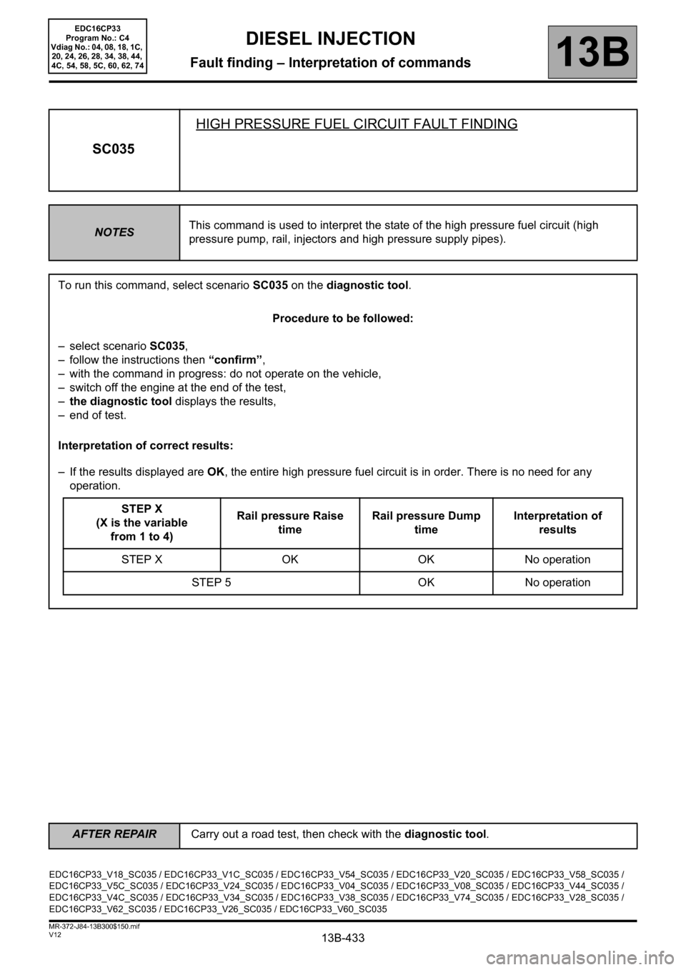
SC035HIGH PRESSURE FUEL CIRCUIT FAULT FINDING
NOTESThis command is used to interpret the state of the high pressure fuel circuit (high
pressure pump, rail, injectors and high pressure supply pipes).
To run this command, select scenario SC035 on the diagnostic tool.
Procedure to be followed:
– select scenario SC035,
– follow the instructions then “confirm”,
– with the command in progress: do not operate on the vehicle,
– switch off the engine at the end of the test,
–the diagnostic tool displays the results,
– end of test.
Interpretation of correct results:
– If the results displayed are OK, the entire high pressure fuel circuit is in order. There is no need for any
operation.
STEP X
(X is the variable
from 1 to 4)Rail pressure Raise
timeRail pressure Dump
timeInterpretation of
results
STEP X OK OK No operation
STEP 5 OK No operation
EDC16CP33_V18_SC035 / EDC16CP33_V1C_SC035 / EDC16CP33_V54_SC035 / EDC16CP33_V20_SC035 / EDC16CP33_V58_SC035 /
EDC16CP33_V5C_SC035 / EDC16CP33_V24_SC035 / EDC16CP33_V04_SC035 / EDC16CP33_V08_SC035 / EDC16CP33_V44_SC035 /
EDC16CP33_V4C_SC035 / EDC16CP33_V34_SC035 / EDC16CP33_V38_SC035 / EDC16CP33_V74_SC035 / EDC16CP33_V28_SC035 /
EDC16CP33_V62_SC035 / EDC16CP33_V26_SC035 / EDC16CP33_V60_SC035
EDC16CP33
Program No.: C4
Vdiag No.: 04, 08, 18, 1C,
20, 24, 26, 28, 34, 38, 44,
4C, 54, 58, 5C, 60, 62, 74
AFTER REPAIRCarry out a road test, then check with the diagnostic tool.
Page 434 of 510

13B-434V12 MR-372-J84-13B300$150.mif
DIESEL INJECTION
Fault finding – Interpretation of commands13B
SC035
CONTINUED 1
Interpretation of incorrect results:
– Is one of the value definitions for the various displayed stages is “TOO SLOW” or “TOO FAST”, see the
following table:
STEP X
(X is the variable
from 1 to 4)Rail pressure Raise
timeRail pressure Dump
timeInterpretation of
results
STEP X TOO SLOW TOO SLOW Check 1
STEP X TOO SLOW TOO FAST Check 2
STEP X TOO SLOW OK Check 3
STEP X OK TOO SLOW Check 4
STEP X OK TOO FAST Check 5
STEP 5 TOO FAST Check 5
Explanation of results interpretation:
Check 1:
–Apply Test 10 Poor injector operation.
–Apply ALP6 Fuel circuit leaks.
–Apply Test 3 Low pressure circuit check.
– Replace the high pressure pump.
Check 2:
–Apply Test 10.
–Apply ALP6.
– Apply the part of Test 3 concerning the fuel filter.
– Replace the high pressure pump.
– Check the injector return flow and the injectors.
– Check the rail pressure regulator by running command AC225 Rail pressure regulator.
EDC16CP33
Program No.: C4
Vdiag No.: 04, 08, 18, 1C,
20, 24, 26, 28, 34, 38, 44,
4C, 54, 58, 5C, 60, 62, 74
AFTER REPAIRCarry out a road test, then check with the diagnostic tool.
Page 456 of 510
13B-456V12 MR-372-J84-13B300$150.mif
DIESEL INJECTION
Fault finding – Interpretation of commands13B
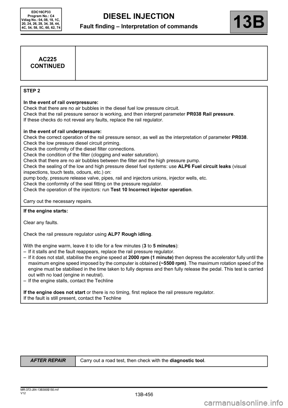
AC225
CONTINUED
STEP 2
In the event of rail overpressure:
Check that there are no air bubbles in the diesel fuel low pressure circuit.
Check that the rail pressure sensor is working, and then interpret parameter PR038 Rail pressure.
If these checks do not reveal any faults, replace the rail regulator.
in the event of rail underpressure:
Check the correct operation of the rail pressure sensor, as well as the interpretation of parameter PR038.
Check the low pressure diesel circuit priming.
Check the conformity of the diesel filter connections.
Check the condition of the filter (clogging and water saturation).
Check that there are no air bubbles between the filter and the high pressure pump.
Check the sealing of the low and high pressure diesel fuel systems: use ALP6 Fuel circuit leaks (visual
inspections, touch tests, odours, etc.) on:
pump body, pressure release valve, pipes, rail and injectors unions, injector wells, etc.
Check the conformity of the seal fitting on the pressure regulator.
Check the operation of the injectors: run Test 10 Incorrect injector operation.
Carry out the necessary repairs.
If the engine starts:
Clear any faults.
Check the rail pressure regulator using ALP7 Rough idling.
With the engine warm, leave it to idle for a few minutes (3 to 5 minutes):
– If it stalls and the fault reappears, replace the rail pressure regulator.
– If it does not stall, stabilise the engine speed at 2000 rpm (1 minute) then depress the accelerator fully until the
maximum engine speed imposed by the computer is obtained (~5500 rpm). The maximum rotation speed of the
engine must be stabilised in the time taken to fully depress and then fully release the pedal. This test is carried
out with no load (engine in neutral).
– If the engine stalls, contact the Techline
If the engine does not start or there is no timing, first replace the rail pressure regulator.
If the fault is still present, contact the Techline
EDC16CP33
Program No.: C4
Vdiag No.: 04, 08, 18, 1C,
20, 24, 26, 28, 34, 38, 44,
4C, 54, 58, 5C, 60, 62, 74
AFTER REPAIRCarry out a road test, then check with the diagnostic tool.
Page 458 of 510
13B-458V12 MR-372-J84-13B300$150.mif
DIESEL INJECTION
Fault finding – Interpretation of commands13B
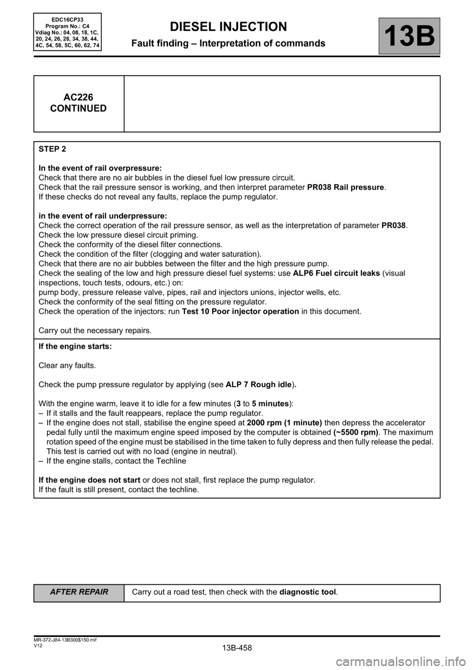
AC226
CONTINUED
STEP 2
In the event of rail overpressure:
Check that there are no air bubbles in the diesel fuel low pressure circuit.
Check that the rail pressure sensor is working, and then interpret parameter PR038 Rail pressure.
If these checks do not reveal any faults, replace the pump regulator.
in the event of rail underpressure:
Check the correct operation of the rail pressure sensor, as well as the interpretation of parameter PR038.
Check the low pressure diesel circuit priming.
Check the conformity of the diesel filter connections.
Check the condition of the filter (clogging and water saturation).
Check that there are no air bubbles between the filter and the high pressure pump.
Check the sealing of the low and high pressure diesel fuel systems: use ALP6 Fuel circuit leaks (visual
inspections, touch tests, odours, etc.) on:
pump body, pressure release valve, pipes, rail and injectors unions, injector wells, etc.
Check the conformity of the seal fitting on the pressure regulator.
Check the operation of the injectors: run Test 10 Poor injector operation in this document.
Carry out the necessary repairs.
If the engine starts:
Clear any faults.
Check the pump pressure regulator by applying (see ALP 7 Rough idle).
With the engine warm, leave it to idle for a few minutes (3 to 5 minutes):
– If it stalls and the fault reappears, replace the pump regulator.
– If the engine does not stall, stabilise the engine speed at 2000 rpm (1 minute) then depress the accelerator
pedal fully until the maximum engine speed imposed by the computer is obtained (~5500 rpm). The maximum
rotation speed of the engine must be stabilised in the time taken to fully depress and then fully release the pedal.
This test is carried out with no load (engine in neutral).
– If the engine stalls, contact the Techline
If the engine does not start or does not stall, first replace the pump regulator.
If the fault is still present, contact the techline.
EDC16CP33
Program No.: C4
Vdiag No.: 04, 08, 18, 1C,
20, 24, 26, 28, 34, 38, 44,
4C, 54, 58, 5C, 60, 62, 74
AFTER REPAIRCarry out a road test, then check with the diagnostic tool.
Page 461 of 510
13B-461V12 MR-372-J84-13B300$150.mif
DIESEL INJECTION
Fault finding – Interpretation of commands13B
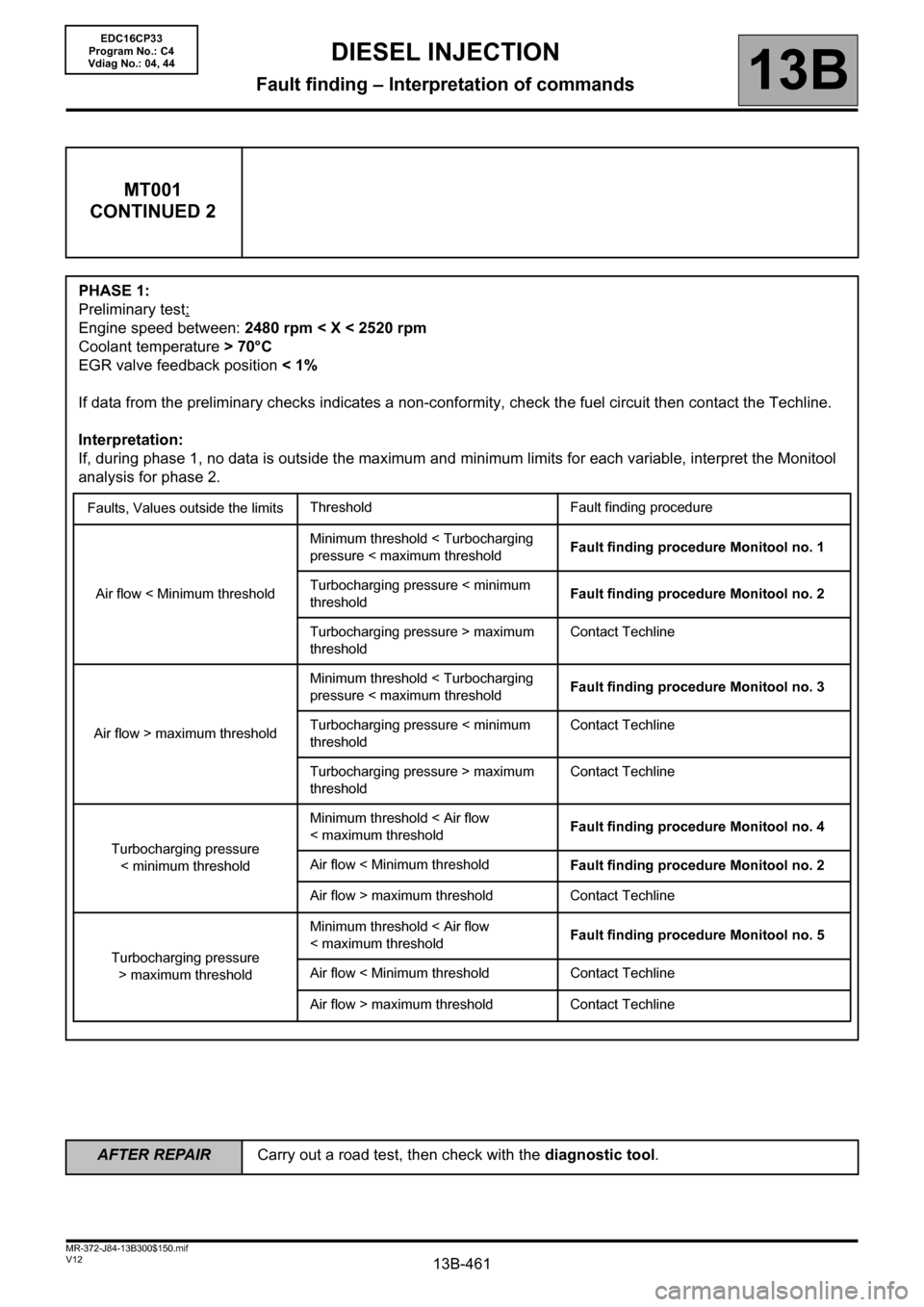
MT001
CONTINUED 2
PHASE 1:
Preliminary test:
Engine speed between: 2480 rpm < X < 2520 rpm
Coolant temperature > 70°C
EGR valve feedback position < 1%
If data from the preliminary checks indicates a non-conformity, check the fuel circuit then contact the Techline.
Interpretation:
If, during phase 1, no data is outside the maximum and minimum limits for each variable, interpret the Monitool
analysis for phase 2.
Faults, Values outside the limitsThreshold Fault finding procedure
Air flow < Minimum thresholdMinimum threshold < Turbocharging
pressure < maximum thresholdFault finding procedure Monitool no. 1
Turbocharging pressure < minimum
thresholdFault finding procedure Monitool no. 2
Turbocharging pressure > maximum
thresholdContact Techline
Air flow > maximum thresholdMinimum threshold < Turbocharging
pressure < maximum thresholdFault finding procedure Monitool no. 3
Turbocharging pressure < minimum
thresholdContact Techline
Turbocharging pressure > maximum
thresholdContact Techline
Turbocharging pressure
< minimum thresholdMinimum threshold < Air flow
< maximum thresholdFault finding procedure Monitool no. 4
Air flow < Minimum threshold
Fault finding procedure Monitool no. 2
Air flow > maximum threshold Contact Techline
Turbocharging pressure
> maximum thresholdMinimum threshold < Air flow
< maximum thresholdFault finding procedure Monitool no. 5
Air flow < Minimum threshold Contact Techline
Air flow > maximum threshold Contact Techline
EDC16CP33
Program No.: C4
Vdiag No.: 04, 44
AFTER REPAIRCarry out a road test, then check with the diagnostic tool.
Page 466 of 510
13B-466V12 MR-372-J84-13B300$150.mif
DIESEL INJECTION
Fault finding – Interpretation of commands13B
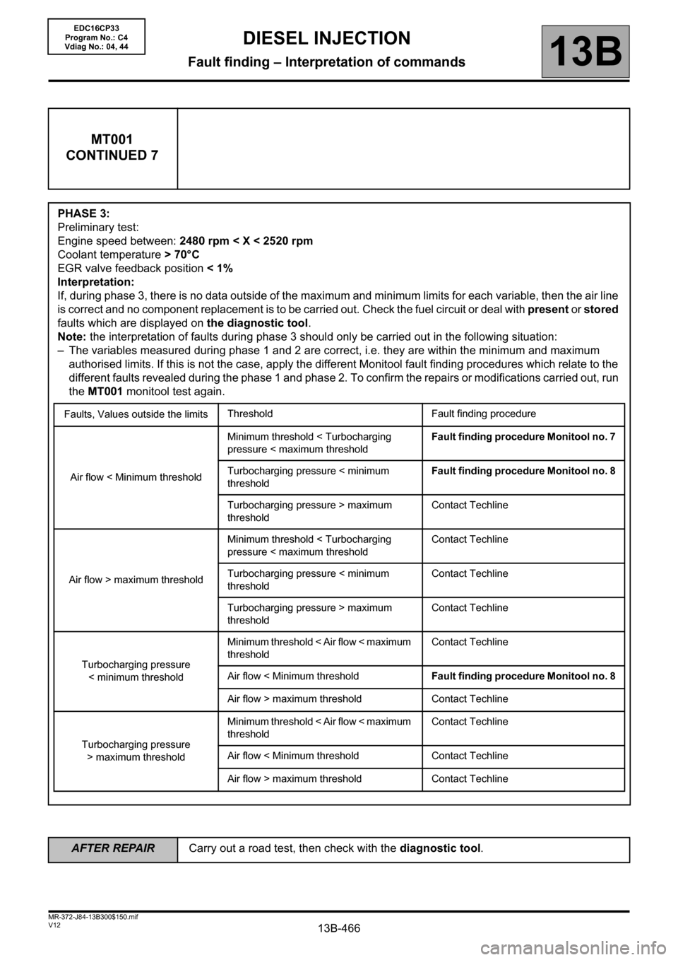
MT001
CONTINUED 7
PHASE 3:
Preliminary test:
Engine speed between: 2480 rpm < X < 2520 rpm
Coolant temperature > 70°C
EGR valve feedback position < 1%
Interpretation:
If, during phase 3, there is no data outside of the maximum and minimum limits for each variable, then the air line
is correct and no component replacement is to be carried out. Check the fuel circuit or deal with present or stored
faults which are displayed on the diagnostic tool.
Note: the interpretation of faults during phase 3 should only be carried out in the following situation:
– The variables measured during phase 1 and 2 are correct, i.e. they are within the minimum and maximum
authorised limits. If this is not the case, apply the different Monitool fault finding procedures which relate to the
different faults revealed during the phase 1 and phase 2. To confirm the repairs or modifications carried out, run
the MT001 monitool test again.
Faults, Values outside the limitsThreshold Fault finding procedure
Air flow < Minimum thresholdMinimum threshold < Turbocharging
pressure < maximum thresholdFault finding procedure Monitool no. 7
Turbocharging pressure < minimum
thresholdFault finding procedure Monitool no. 8
Turbocharging pressure > maximum
thresholdContact Techline
Air flow > maximum thresholdMinimum threshold < Turbocharging
pressure < maximum thresholdContact Techline
Turbocharging pressure < minimum
thresholdContact Techline
Turbocharging pressure > maximum
thresholdContact Techline
Turbocharging pressure
< minimum thresholdMinimum threshold < Air flow < maximum
thresholdContact Techline
Air flow < Minimum thresholdFault finding procedure Monitool no. 8
Air flow > maximum threshold Contact Techline
Turbocharging pressure
> maximum thresholdMinimum threshold < Air flow < maximum
thresholdContact Techline
Air flow < Minimum threshold Contact Techline
Air flow > maximum threshold Contact Techline
EDC16CP33
Program No.: C4
Vdiag No.: 04, 44
AFTER REPAIRCarry out a road test, then check with the diagnostic tool.
Page 468 of 510
13B-468V12 MR-372-J84-13B300$150.mif
DIESEL INJECTION
Fault finding – Interpretation of commands13B
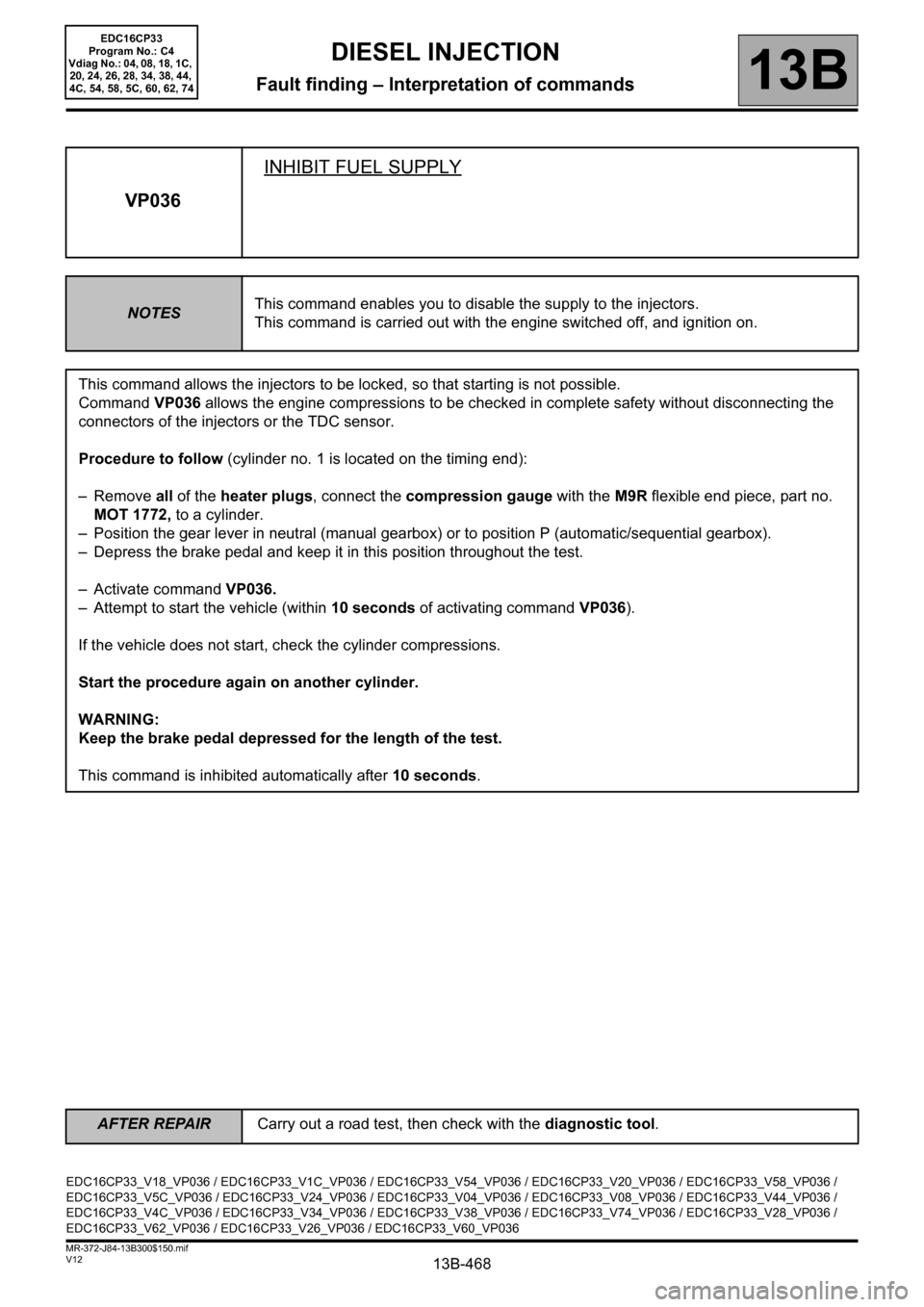
VP036INHIBIT FUEL SUPPLY
NOTESThis command enables you to disable the supply to the injectors.
This command is carried out with the engine switched off, and ignition on.
This command allows the injectors to be locked, so that starting is not possible.
Command VP036 allows the engine compressions to be checked in complete safety without disconnecting the
connectors of the injectors or the TDC sensor.
Procedure to follow (cylinder no. 1 is located on the timing end):
– Remove all of the heater plugs, connect the compression gauge with the M9R flexible end piece, part no.
MOT 1772, to a cylinder.
– Position the gear lever in neutral (manual gearbox) or to position P (automatic/sequential gearbox).
– Depress the brake pedal and keep it in this position throughout the test.
– Activate command VP036.
– Attempt to start the vehicle (within 10 seconds of activating command VP036).
If the vehicle does not start, check the cylinder compressions.
Start the procedure again on another cylinder.
WARNING:
Keep the brake pedal depressed for the length of the test.
This command is inhibited automatically after 10 seconds.
EDC16CP33_V18_VP036 / EDC16CP33_V1C_VP036 / EDC16CP33_V54_VP036 / EDC16CP33_V20_VP036 / EDC16CP33_V58_VP036 /
EDC16CP33_V5C_VP036 / EDC16CP33_V24_VP036 / EDC16CP33_V04_VP036 / EDC16CP33_V08_VP036 / EDC16CP33_V44_VP036 /
EDC16CP33_V4C_VP036 / EDC16CP33_V34_VP036 / EDC16CP33_V38_VP036 / EDC16CP33_V74_VP036 / EDC16CP33_V28_VP036 /
EDC16CP33_V62_VP036 / EDC16CP33_V26_VP036 / EDC16CP33_V60_VP036
EDC16CP33
Program No.: C4
Vdiag No.: 04, 08, 18, 1C,
20, 24, 26, 28, 34, 38, 44,
4C, 54, 58, 5C, 60, 62, 74
AFTER REPAIRCarry out a road test, then check with the diagnostic tool.
Page 469 of 510
13B-469
AFTER REPAIRCarry out a road test followed by a check with the diagnostic tool.
V12 MR-372-J84-13B300$160.mif
13B
EDC16CP33
Program No.: C4
Vdiag No.: 04, 08, 18, 1C,
20, 24, 26, 28, 34, 38, 44,
4C, 54, 58, 5C, 60, 62, 74
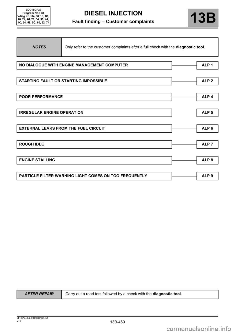
NOTESOnly refer to the customer complaints after a full check with the diagnostic tool.
NO DIALOGUE WITH ENGINE MANAGEMENT COMPUTER ALP 1
STARTING FAULT OR STARTING IMPOSSIBLE ALP 2
POOR PERFORMANCEALP 4
IRREGULAR ENGINE OPERATION ALP 5
EXTERNAL LEAKS FROM THE FUEL CIRCUIT ALP 6
ROUGH IDLEALP 7
ENGINE STALLINGALP 8
PARTICLE FILTER WARNING LIGHT COMES ON TOO FREQUENTLY ALP 9
DIESEL INJECTION
Fault finding – Customer complaints
Page 473 of 510
13B-473
AFTER REPAIRCarry out a road test, then check with the diagnostic tool.
V12 MR-372-J84-13B300$170.mif
DIESEL INJECTION
Fault finding – Fault Finding Chart13B
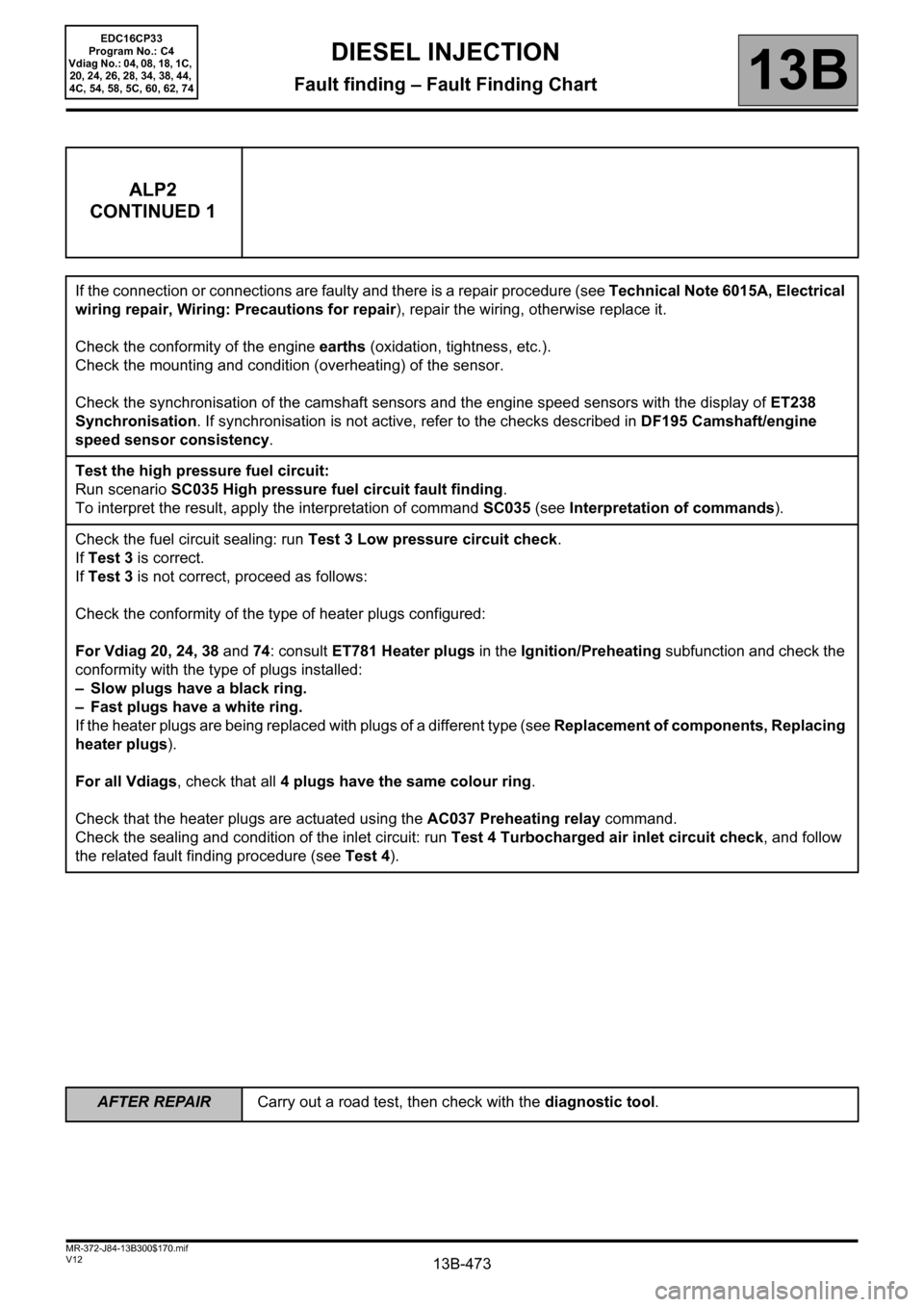
ALP2
CONTINUED 1
If the connection or connections are faulty and there is a repair procedure (see Technical Note 6015A, Electrical
wiring repair, Wiring: Precautions for repair), repair the wiring, otherwise replace it.
Check the conformity of the engine earths (oxidation, tightness, etc.).
Check the mounting and condition (overheating) of the sensor.
Check the synchronisation of the camshaft sensors and the engine speed sensors with the display of ET238
Synchronisation. If synchronisation is not active, refer to the checks described in DF195 Camshaft/engine
speed sensor consistency.
Test the high pressure fuel circuit:
Run scenario SC035 High pressure fuel circuit fault finding.
To interpret the result, apply the interpretation of command SC035 (see Interpretation of commands).
Check the fuel circuit sealing: run Test 3 Low pressure circuit check.
If Test 3 is correct.
If Test 3 is not correct, proceed as follows:
Check the conformity of the type of heater plugs configured:
For Vdiag 20, 24, 38 and 74: consult ET781 Heater plugs in the Ignition/Preheating subfunction and check the
conformity with the type of plugs installed:
– Slow plugs have a black ring.
– Fast plugs have a white ring.
If the heater plugs are being replaced with plugs of a different type (see Replacement of components, Replacing
heater plugs).
For all Vdiags, check that all 4 plugs have the same colour ring.
Check that the heater plugs are actuated using the AC037 Preheating relay command.
Check the sealing and condition of the inlet circuit: run Test 4 Turbocharged air inlet circuit check, and follow
the related fault finding procedure (see Test 4).
EDC16CP33
Program No.: C4
Vdiag No.: 04, 08, 18, 1C,
20, 24, 26, 28, 34, 38, 44,
4C, 54, 58, 5C, 60, 62, 74