DF569 RENAULT SCENIC 2012 J95 / 3.G Engine And Peripherals EDC16CP33 Workshop Manual
[x] Cancel search | Manufacturer: RENAULT, Model Year: 2012, Model line: SCENIC, Model: RENAULT SCENIC 2012 J95 / 3.GPages: 510, PDF Size: 2.98 MB
Page 20 of 510
13B-20V12 MR-372-J84-13B300$030.mif
DIESEL INJECTION
Fault finding – System operation13B
EDC16CP33
Program No.: C4
Vdiag No.: 04, 08, 18, 1C,
20, 24, 26, 28, 34, 38, 44,
4C, 54, 58, 5C, 60, 62, 74
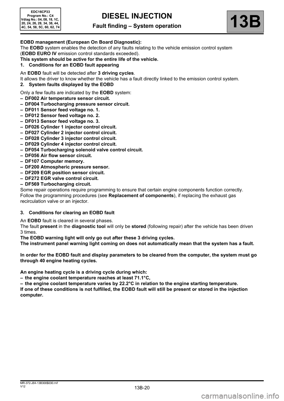
EOBD management (European On Board Diagnostic):
The EOBD system enables the detection of any faults relating to the vehicle emission control system
(EOBD EURO IV emission control standards exceeded).
This system should be active for the entire life of the vehicle.
1. Conditions for an EOBD fault appearing
An EOBD fault will be detected after 3 driving cycles.
It allows the driver to know whether the vehicle has a fault directly linked to the emission control system.
2. System faults displayed by the EOBD
Only a few faults are indicated by the EOBD system:
– DF002 Air temperature sensor circuit.
– DF004 Turbocharging pressure sensor circuit.
– DF011 Sensor feed voltage no. 1.
– DF012 Sensor feed voltage no. 2.
– DF013 Sensor feed voltage no. 3.
– DF026 Cylinder 1 injector control circuit.
– DF027 Cylinder 2 injector control circuit.
– DF028 Cylinder 3 injector control circuit.
– DF029 Cylinder 4 injector control circuit.
– DF054 Turbocharging solenoid valve control circuit.
– DF056 Air flow sensor circuit.
– DF107 Computer memory.
– DF200 Atmospheric pressure sensor.
– DF209 EGR position sensor circuit.
– DF272 EGR valve control circuit.
– DF569 Turbocharging circuit.
Some repair operations require programming to ensure that certain engine components function correctly.
Follow the programming procedures (see Replacement of components), if replacing the exhaust gas
recirculation valve or an injector.
3. Conditions for clearing an EOBD fault
An EOBD fault is cleared in several phases.
The fault present in the diagnostic tool will only be stored (following repair) after the vehicle has been driven
3times.
The EOBD warning light will only go out after these 3 driving cycles.
The instrument panel warning light coming on does not automatically mean that the system has a fault.
In order for the EOBD fault and display parameters to be cleared from the computer, the system must go
through 40 engine heating cycles.
An engine heating cycle is a driving cycle during which:
– the engine coolant temperature reaches at least 71.1°C,
– the engine coolant temperature varies by 22.2°C in relation to the engine starting temperature.
If one of these conditions is not fulfilled, the EOBD fault will still be present or stored in the injection
computer.
Page 30 of 510
13B-30V12 MR-372-J84-13B300$060.mif
DIESEL INJECTION
Fault finding – Fault summary table13B
EDC16CP33
Program No.: C4
Vdiag No.: 04, 08, 18, 1C,
20, 24, 26, 28, 34, 38, 44,
4C, 54, 58, 5C, 60, 62, 74
* temp: Temperature
* Diff: Differential
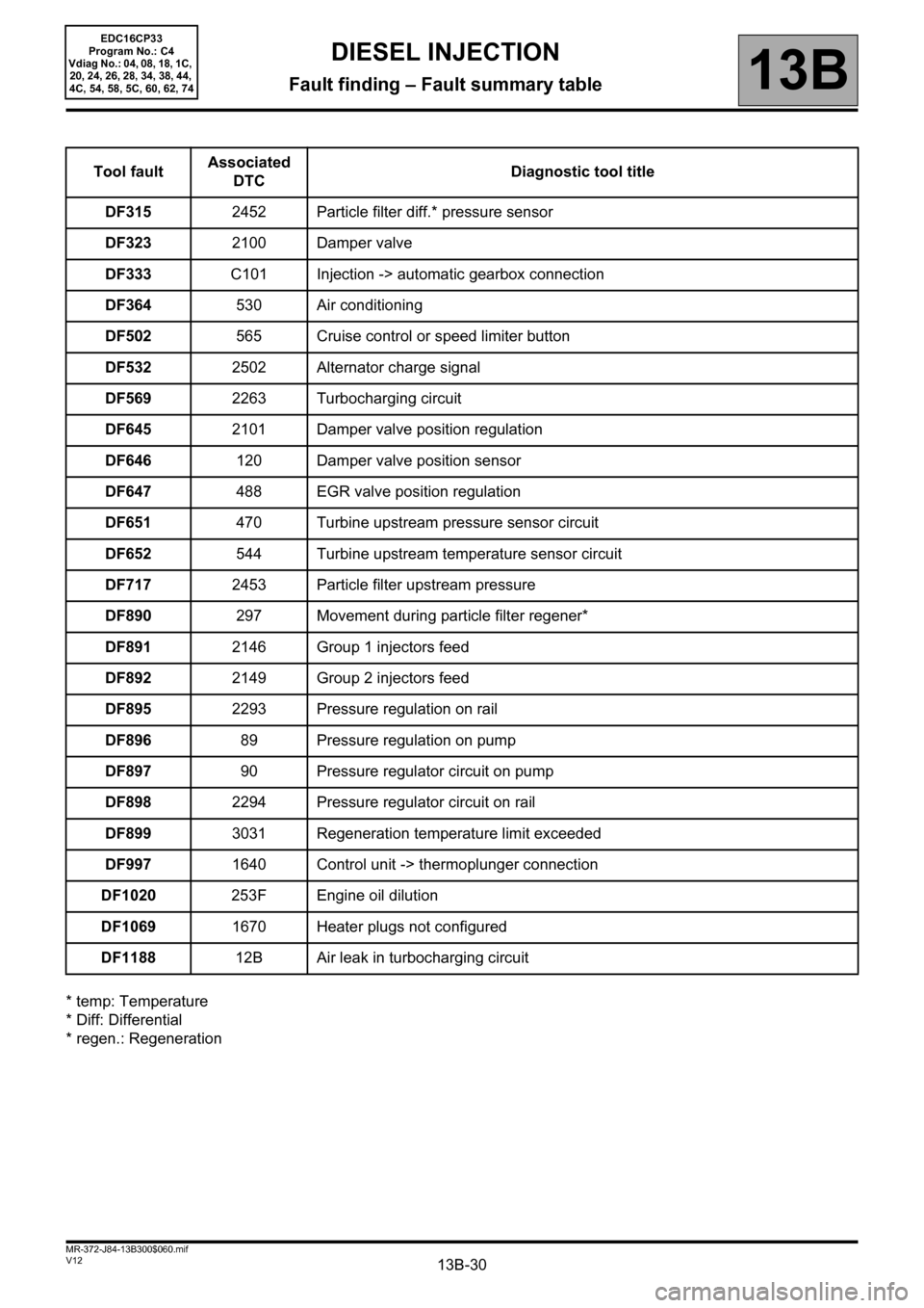
* regen.: RegenerationTool faultAssociated
DTCDiagnostic tool title
DF3152452 Particle filter diff.* pressure sensor
DF3232100 Damper valve
DF333C101 Injection -> automatic gearbox connection
DF364530 Air conditioning
DF502565 Cruise control or speed limiter button
DF5322502 Alternator charge signal
DF5692263 Turbocharging circuit
DF6452101 Damper valve position regulation
DF646120 Damper valve position sensor
DF647488 EGR valve position regulation
DF651470 Turbine upstream pressure sensor circuit
DF652544 Turbine upstream temperature sensor circuit
DF7172453 Particle filter upstream pressure
DF890297 Movement during particle filter regener*
DF8912146 Group 1 injectors feed
DF8922149 Group 2 injectors feed
DF8952293 Pressure regulation on rail
DF89689 Pressure regulation on pump
DF89790 Pressure regulator circuit on pump
DF8982294 Pressure regulator circuit on rail
DF8993031 Regeneration temperature limit exceeded
DF9971640 Control unit -> thermoplunger connection
DF1020253F Engine oil dilution
DF10691670 Heater plugs not configured
DF118812B Air leak in turbocharging circuit
Page 197 of 510
13B-197
AFTER REPAIRDeal with any other faults. Clear the fault memory.
Switch off the ignition until the end of the power-latch phase, and carry out a road test
followed by a check with the diagnostic tool.
V12 MR-372-J84-13B300$073.mif
DIESEL INJECTION
Fault finding – Interpretation of faults13B
diff.*: Differential
temp.*: Temperature
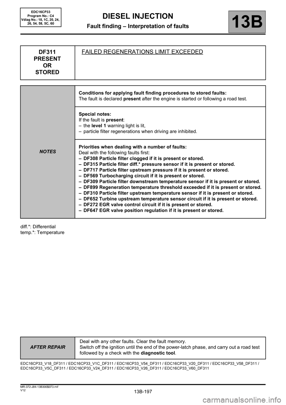
DF311
PRESENT
OR
STOREDFAILED REGENERATIONS LIMIT EXCEEDED
NOTESConditions for applying fault finding procedures to stored faults:
The fault is declared present after the engine is started or following a road test.
Special notes:
If the fault is present:
–the level 1 warning light is lit,
– particle filter regenerations when driving are inhibited.
Priorities when dealing with a number of faults:
Deal with the following faults first:
– DF308 Particle filter clogged if it is present or stored.
– DF315 Particle filter diff.* pressure sensor if it is present or stored.
– DF717 Particle filter upstream pressure if it is present or stored.
– DF569 Turbocharging circuit if it is present or stored.
– DF309 Particle filter downstream temperature sensor if it is present or stored.
– DF899 Regeneration temperature threshold exceeded if it is present or stored.
– DF310 Particle filter upstream temperature sensor if it is present or stored.
– DF652 Turbine upstream temperature sensor circuit if it is present or stored.
– DF272 EGR valve control circuit if it is present or stored.
– DF647 EGR valve position regulation if it is present or stored.
EDC16CP33_V18_DF311 / EDC16CP33_V1C_DF311 / EDC16CP33_V54_DF311 / EDC16CP33_V20_DF311 / EDC16CP33_V58_DF311 /
EDC16CP33_V5C_DF311 / EDC16CP33_V24_DF311 / EDC16CP33_V26_DF311 / EDC16CP33_V60_DF311
EDC16CP33
Program No.: C4
Vdiag No.: 18, 1C, 20, 24,
26, 54, 58, 5C, 60
Page 218 of 510
13B-218
AFTER REPAIRDeal with any other faults. Clear the fault memory.
Switch off the ignition until the end of the power-latch phase, and carry out a road test
followed by a check with the diagnostic tool.
V12 MR-372-J84-13B300$074.mif
DIESEL INJECTION
Fault finding – Interpretation of faults13B
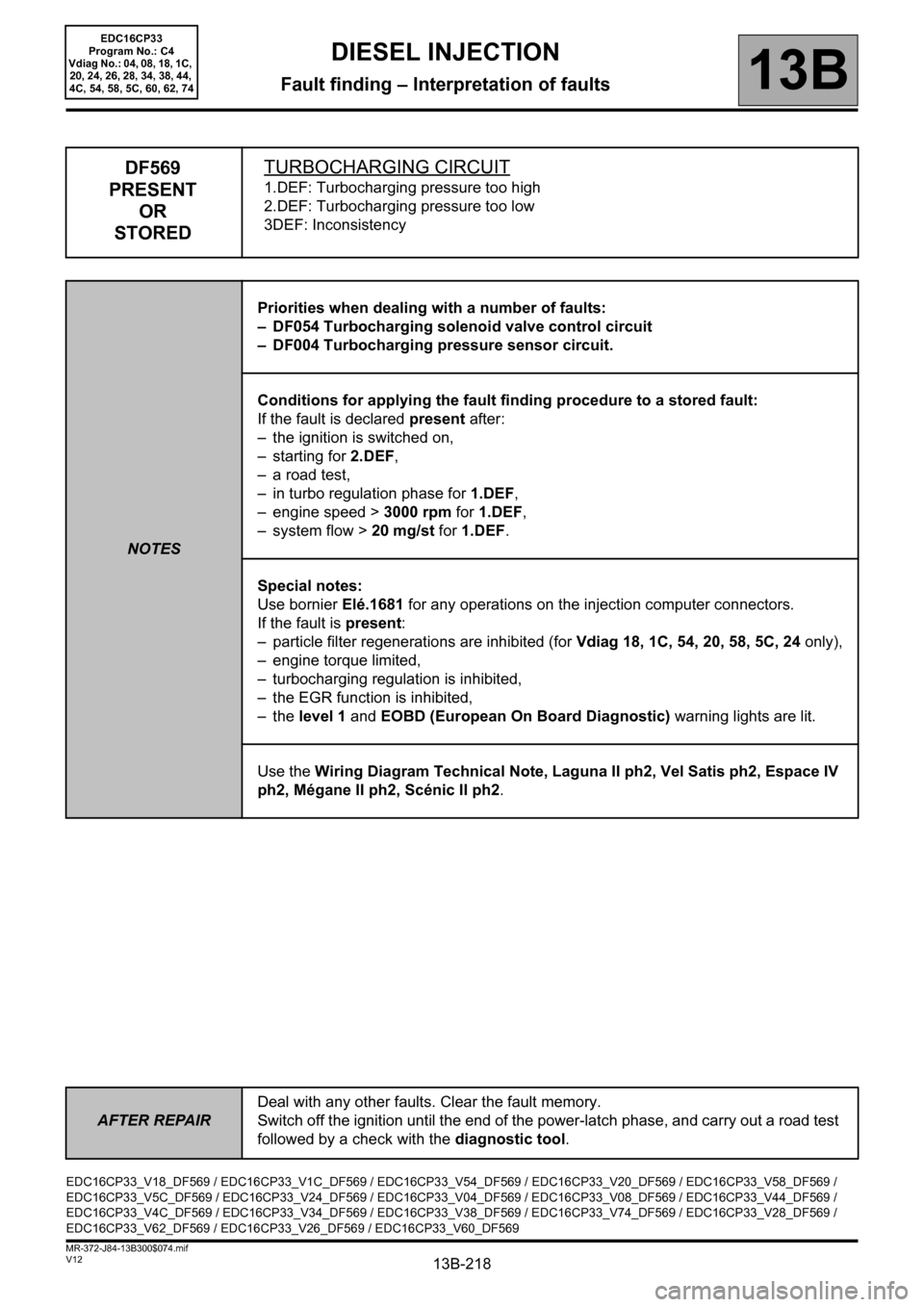
DF569
PRESENT
OR
STOREDTURBOCHARGING CIRCUIT
1.DEF: Turbocharging pressure too high
2.DEF: Turbocharging pressure too low
3DEF: Inconsistency
NOTESPriorities when dealing with a number of faults:
– DF054 Turbocharging solenoid valve control circuit
– DF004 Turbocharging pressure sensor circuit.
Conditions for applying the fault finding procedure to a stored fault:
If the fault is declared present after:
– the ignition is switched on,
– starting for 2.DEF,
– a road test,
– in turbo regulation phase for 1.DEF,
– engine speed > 3000 rpm for 1.DEF,
– system flow > 20 mg/st for 1.DEF.
Special notes:
Use bornier Elé.1681 for any operations on the injection computer connectors.
If the fault is present:
– particle filter regenerations are inhibited (for Vdiag 18, 1C, 54, 20, 58, 5C, 24 only),
– engine torque limited,
– turbocharging regulation is inhibited,
– the EGR function is inhibited,
–the level 1 and EOBD (European On Board Diagnostic) warning lights are lit.
Use the Wiring Diagram Technical Note, Laguna II ph2, Vel Satis ph2, Espace IV
ph2, Mégane II ph2, Scénic II ph2.
EDC16CP33_V18_DF569 / EDC16CP33_V1C_DF569 / EDC16CP33_V54_DF569 / EDC16CP33_V20_DF569 / EDC16CP33_V58_DF569 /
EDC16CP33_V5C_DF569 / EDC16CP33_V24_DF569 / EDC16CP33_V04_DF569 / EDC16CP33_V08_DF569 / EDC16CP33_V44_DF569 /
EDC16CP33_V4C_DF569 / EDC16CP33_V34_DF569 / EDC16CP33_V38_DF569 / EDC16CP33_V74_DF569 / EDC16CP33_V28_DF569 /
EDC16CP33_V62_DF569 / EDC16CP33_V26_DF569 / EDC16CP33_V60_DF569
EDC16CP33
Program No.: C4
Vdiag No.: 04, 08, 18, 1C,
20, 24, 26, 28, 34, 38, 44,
4C, 54, 58, 5C, 60, 62, 74
Page 219 of 510
13B-219
AFTER REPAIRDeal with any other faults. Clear the fault memory.
Switch off the ignition until the end of the power-latch phase, and carry out a road test
followed by a check with the diagnostic tool.
V12 MR-372-J84-13B300$074.mif
DIESEL INJECTION
Fault finding – Interpretation of faults13B
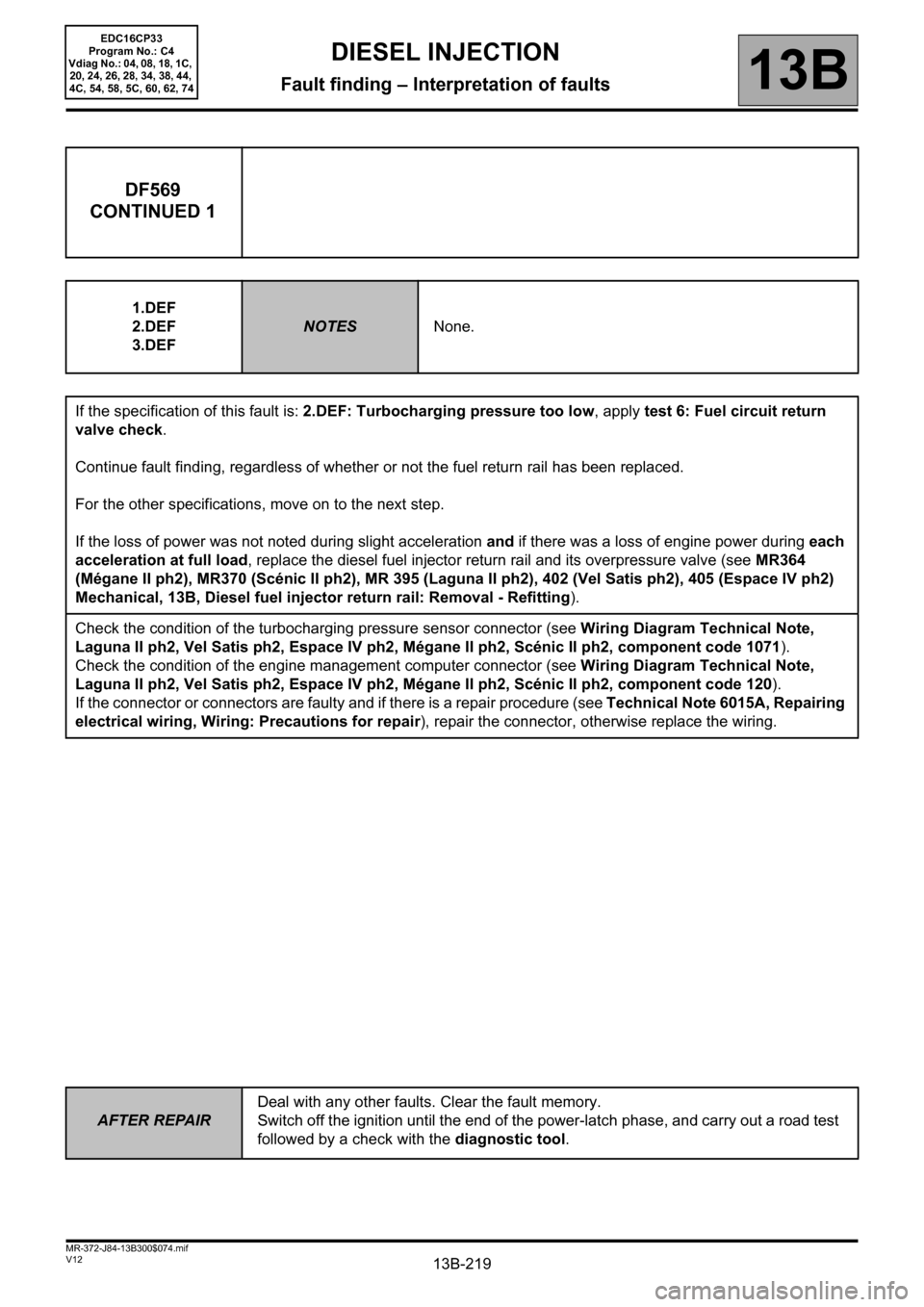
DF569
CONTINUED 1
1.DEF
2.DEF
3.DEF
NOTESNone.
If the specification of this fault is: 2.DEF: Turbocharging pressure too low, apply test 6: Fuel circuit return
valve check.
Continue fault finding, regardless of whether or not the fuel return rail has been replaced.
For the other specifications, move on to the next step.
If the loss of power was not noted during slight acceleration and if there was a loss of engine power during each
acceleration at full load, replace the diesel fuel injector return rail and its overpressure valve (see MR364
(Mégane II ph2), MR370 (Scénic II ph2), MR 395 (Laguna II ph2), 402 (Vel Satis ph2), 405 (Espace IV ph2)
Mechanical, 13B, Diesel fuel injector return rail: Removal - Refitting).
Check the condition of the turbocharging pressure sensor connector (see Wiring Diagram Technical Note,
Laguna II ph2, Vel Satis ph2, Espace IV ph2, Mégane II ph2, Scénic II ph2, component code 1071).
Check the condition of the engine management computer connector (see Wiring Diagram Technical Note,
Laguna II ph2, Vel Satis ph2, Espace IV ph2, Mégane II ph2, Scénic II ph2, component code 120).
If the connector or connectors are faulty and if there is a repair procedure (see Technical Note 6015A, Repairing
electrical wiring, Wiring: Precautions for repair), repair the connector, otherwise replace the wiring.
EDC16CP33
Program No.: C4
Vdiag No.: 04, 08, 18, 1C,
20, 24, 26, 28, 34, 38, 44,
4C, 54, 58, 5C, 60, 62, 74
Page 220 of 510
13B-220
AFTER REPAIRDeal with any other faults. Clear the fault memory.
Switch off the ignition until the end of the power-latch phase, and carry out a road test
followed by a check with the diagnostic tool.
V12 MR-372-J84-13B300$074.mif
DIESEL INJECTION
Fault finding – Interpretation of faults13B
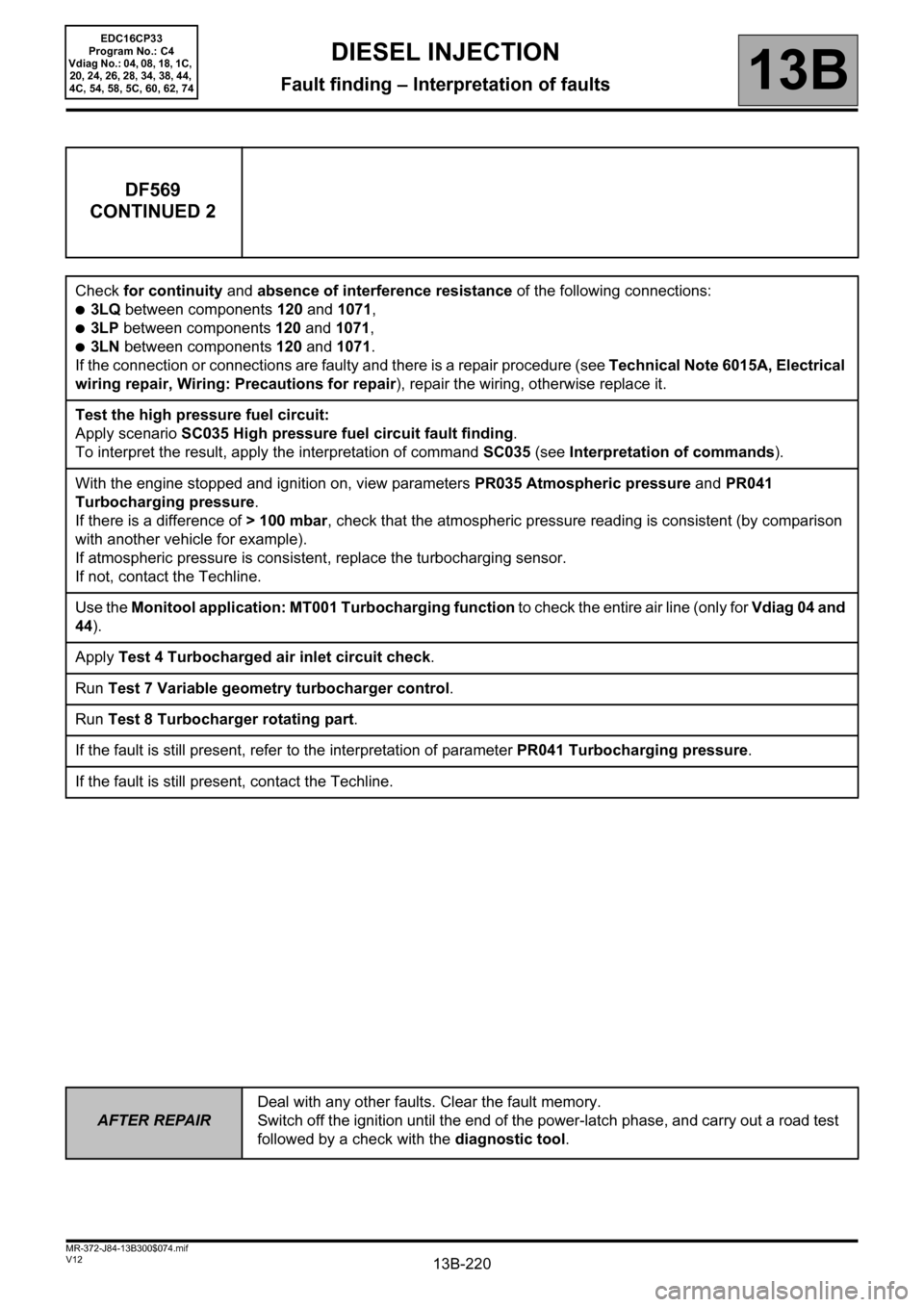
DF569
CONTINUED 2
Check for continuity and absence of interference resistance of the following connections:
●3LQ between components 120 and 1071,
●3LP between components 120 and 1071,
●3LN between components 120 and 1071.
If the connection or connections are faulty and there is a repair procedure (see Technical Note 6015A, Electrical
wiring repair, Wiring: Precautions for repair), repair the wiring, otherwise replace it.
Test the high pressure fuel circuit:
Apply scenario SC035 High pressure fuel circuit fault finding.
To interpret the result, apply the interpretation of command SC035 (see Interpretation of commands).
With the engine stopped and ignition on, view parameters PR035 Atmospheric pressure and PR041
Turbocharging pressure.
If there is a difference of > 100 mbar, check that the atmospheric pressure reading is consistent (by comparison
with another vehicle for example).
If atmospheric pressure is consistent, replace the turbocharging sensor.
If not, contact the Techline.
Use the Monitool application: MT001 Turbocharging function to check the entire air line (only for Vdiag 04 and
44).
Apply Test 4 Turbocharged air inlet circuit check.
Run Test 7 Variable geometry turbocharger control.
Run Test 8 Turbocharger rotating part.
If the fault is still present, refer to the interpretation of parameter PR041 Turbocharging pressure.
If the fault is still present, contact the Techline.
EDC16CP33
Program No.: C4
Vdiag No.: 04, 08, 18, 1C,
20, 24, 26, 28, 34, 38, 44,
4C, 54, 58, 5C, 60, 62, 74
Page 230 of 510
13B-230
AFTER REPAIRDeal with any other faults. Clear the fault memory.
Switch off the ignition until the end of the power-latch phase, and carry out a road test
followed by a check with the diagnostic tool.
V12 MR-372-J84-13B300$074.mif
DIESEL INJECTION
Fault finding – Interpretation of faults13B
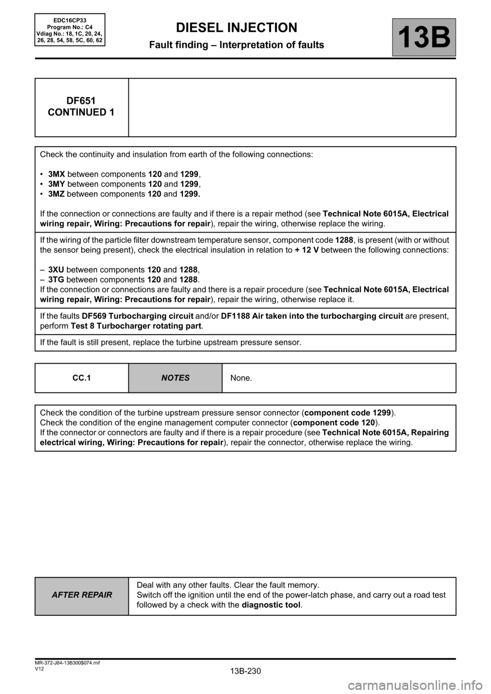
DF651
CONTINUED 1
Check the continuity and insulation from earth of the following connections:
•3MX between components 120 and 1299,
•3MY between components 120 and 1299,
•3MZ between components 120 and 1299.
If the connection or connections are faulty and if there is a repair method (see Technical Note 6015A, Electrical
wiring repair, Wiring: Precautions for repair), repair the wiring, otherwise replace the wiring.
If the wiring of the particle filter downstream temperature sensor, component code 1288, is present (with or without
the sensor being present), check the electrical insulation in relation to + 12 V between the following connections:
–3XU between components 120 and 1288,
–3TG between components 120 and 1288.
If the connection or connections are faulty and there is a repair procedure (see Technical Note 6015A, Electrical
wiring repair, Wiring: Precautions for repair), repair the wiring, otherwise replace it.
If the faults DF569 Turbocharging circuit and/or DF1188 Air taken into the turbocharging circuit are present,
perform Test 8 Turbocharger rotating part.
If the fault is still present, replace the turbine upstream pressure sensor.
CC.1
NOTESNone.
Check the condition of the turbine upstream pressure sensor connector (component code 1299).
Check the condition of the engine management computer connector (component code 120).
If the connector or connectors are faulty and if there is a repair procedure (see Technical Note 6015A, Repairing
electrical wiring, Wiring: Precautions for repair), repair the connector, otherwise replace the wiring.
EDC16CP33
Program No.: C4
Vdiag No.: 18, 1C, 20, 24,
26, 28, 54, 58, 5C, 60, 62
Page 231 of 510
13B-231
AFTER REPAIRDeal with any other faults. Clear the fault memory.
Switch off the ignition until the end of the power-latch phase, and carry out a road test
followed by a check with the diagnostic tool.
V12 MR-372-J84-13B300$074.mif
DIESEL INJECTION
Fault finding – Interpretation of faults13B
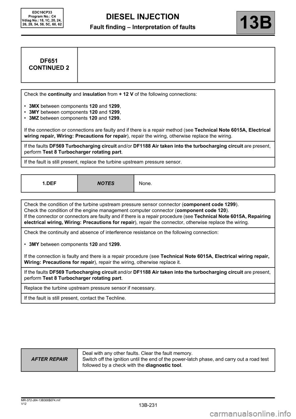
DF651
CONTINUED 2
Check the continuity and insulation from + 12 V of the following connections:
•3MX between components 120 and 1299,
•3MY between components 120 and 1299,
•3MZ between components 120 and 1299.
If the connection or connections are faulty and if there is a repair method (see Technical Note 6015A, Electrical
wiring repair, Wiring: Precautions for repair), repair the wiring, otherwise replace the wiring.
If the faults DF569 Turbocharging circuit and/or DF1188 Air taken into the turbocharging circuit are present,
perform Test 8 Turbocharger rotating part.
If the fault is still present, replace the turbine upstream pressure sensor.
1.DEF
NOTESNone.
Check the condition of the turbine upstream pressure sensor connector (component code 1299).
Check the condition of the engine management computer connector (component code 120).
If the connector or connectors are faulty and if there is a repair procedure (see Technical Note 6015A, Repairing
electrical wiring, Wiring: Precautions for repair), repair the connector, otherwise replace the wiring.
Check the continuity and absence of interference resistance on the following connection:
•3MY between components 120 and 1299.
If the connection is faulty and there is a repair procedure (see Technical Note 6015A, Electrical wiring repair,
Wiring: Precautions for repair), repair the wiring, otherwise replace it.
If the faults DF569 Turbocharging circuit and/or DF1188 Air taken into the turbocharging circuit are present,
perform Test 8 Turbocharger rotating part.
Replace the turbine upstream pressure sensor if necessary.
If the fault is still present, contact the Techline.
EDC16CP33
Program No.: C4
Vdiag No.: 18, 1C, 20, 24,
26, 28, 54, 58, 5C, 60, 62
Page 486 of 510
13B-486
AFTER REPAIRCarry out a road test, then check with the diagnostic tool.
V12 MR-372-J84-13B300$170.mif
DIESEL INJECTION
Fault finding – Fault Finding Chart13B
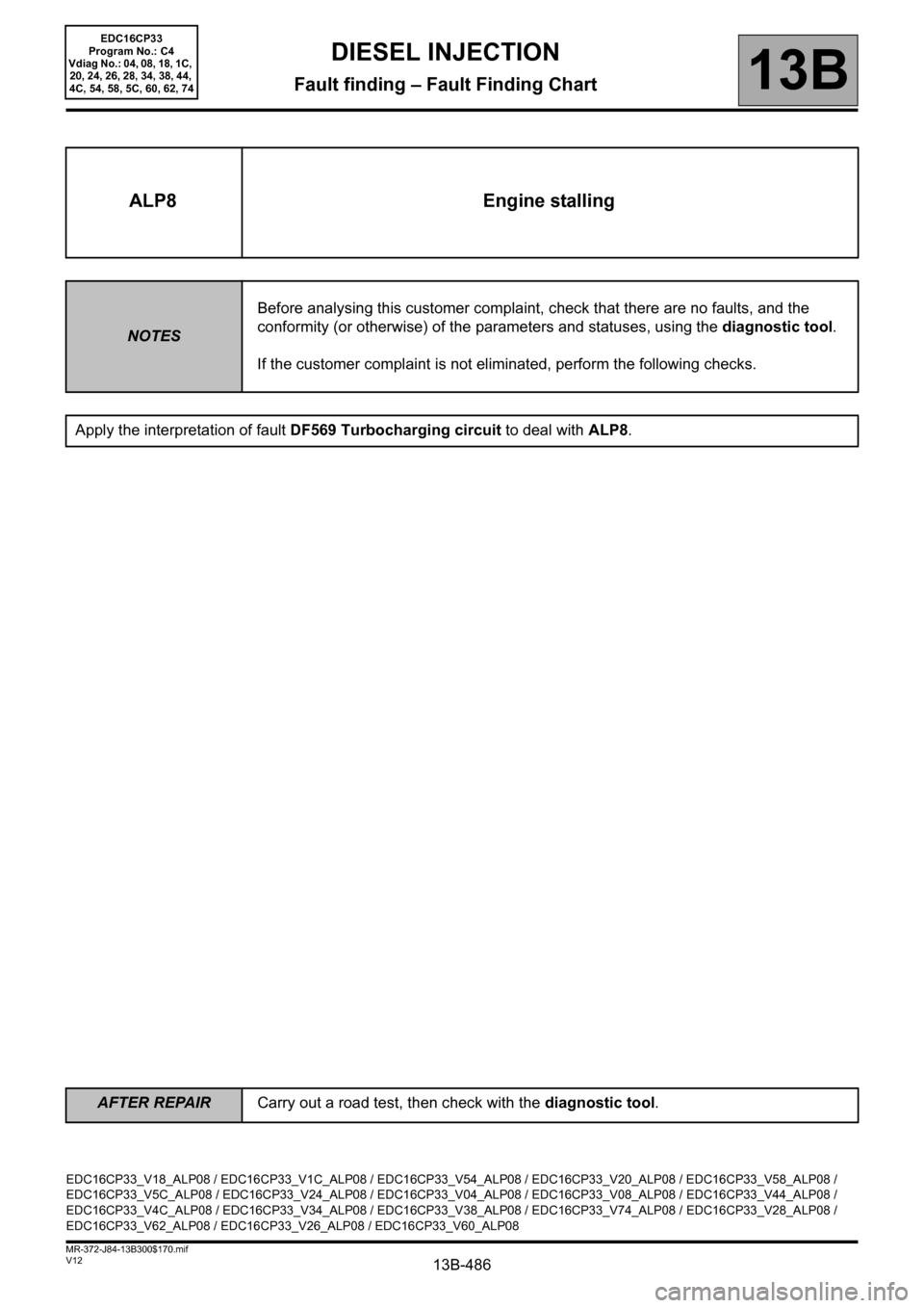
ALP8 Engine stalling
NOTESBefore analysing this customer complaint, check that there are no faults, and the
conformity (or otherwise) of the parameters and statuses, using the diagnostic tool.
If the customer complaint is not eliminated, perform the following checks.
Apply the interpretation of fault DF569 Turbocharging circuit to deal with ALP8.
EDC16CP33_V18_ALP08 / EDC16CP33_V1C_ALP08 / EDC16CP33_V54_ALP08 / EDC16CP33_V20_ALP08 / EDC16CP33_V58_ALP08 /
EDC16CP33_V5C_ALP08 / EDC16CP33_V24_ALP08 / EDC16CP33_V04_ALP08 / EDC16CP33_V08_ALP08 / EDC16CP33_V44_ALP08 /
EDC16CP33_V4C_ALP08 / EDC16CP33_V34_ALP08 / EDC16CP33_V38_ALP08 / EDC16CP33_V74_ALP08 / EDC16CP33_V28_ALP08 /
EDC16CP33_V62_ALP08 / EDC16CP33_V26_ALP08 / EDC16CP33_V60_ALP08
EDC16CP33
Program No.: C4
Vdiag No.: 04, 08, 18, 1C,
20, 24, 26, 28, 34, 38, 44,
4C, 54, 58, 5C, 60, 62, 74