PIN OUT RENAULT SCENIC 2012 J95 / 3.G Engine And Peripherals EDC16CP33 Workshop Manual
[x] Cancel search | Manufacturer: RENAULT, Model Year: 2012, Model line: SCENIC, Model: RENAULT SCENIC 2012 J95 / 3.GPages: 510, PDF Size: 2.98 MB
Page 3 of 510
13B-3V12 MR-372-J84-13B300$010.mif
DIESEL INJECTION
Fault finding – Introduction13B
EDC16CP33
Program No.: C4
Vdiag No.: 04, 08, 18, 1C,
20, 24, 26, 28, 34, 38, 44,
4C, 54, 58, 5C, 60, 62, 74
Faults
Faults are declared present or stored (depending on whether they appeared in a certain context and have
disappeared since, or whether they remain present but are not diagnosed within the current context).
The present or stored status of faults should be taken into consideration when the diagnostic tool is switched on
following + after ignition feed is activated (no system components active).
For a present fault, apply the procedure described in the Interpretation of faults section.
For a stored fault, note the faults displayed and apply the Notes section.
If the fault is confirmed when the instructions are applied, the fault is present. Deal with the fault.
If the fault is not confirmed, check:
– the electrical lines which correspond to the fault,
– the connectors on these lines (corrosion, bent pins, etc.),
– the resistance of the faulty component,
– the condition of the wires (melted or cut insulation, wear).
Conformity check
The purpose of the conformity check is to check data that does not produce a fault on the diagnostic tool if the data
is inconsistent. Therefore, this stage is used to:
– carry out fault finding on faults that do not have a fault display, and which may correspond to a customer complaint.
– check that the system is operating correctly and that there is no risk of a fault recurring after repair.
The conformity check is a fault finding procedure carried out using the interpretation of statuses and parameters.
If a status does not function normally or a parameter is outside the permitted tolerance values, consult the
corresponding fault finding pages (see interpretation of statuses and parameters).
Customer complaints - Fault finding chart
If the test with the diagnostic tool is correct but the customer complaint is still present, the fault should be dealt with
by customer complaints. WARNING:
Deal first with instrument panel faults (eg. "Particle filter" warning light).
Then carry out scheduled maintenance on the vehicle.
A synopsis of the general procedure to follow is provided on the following page in the form of a flow chart.
Page 5 of 510
13B-5V12 MR-372-J84-13B300$010.mif
DIESEL INJECTION
Fault finding – Introduction13B
EDC16CP33
Program No.: C4
Vdiag No.: 04, 08, 18, 1C,
20, 24, 26, 28, 34, 38, 44,
4C, 54, 58, 5C, 60, 62, 74
4. FAULT FINDING PROCEDURE (continued)
4.1 Wiring check
Fault finding problems
Disconnecting the connectors and/or manipulating the wiring may temporarily clear the cause of a fault.
Electrical measurements of voltage, resistance and insulation are generally correct, especially if the fault is not
present when the analysis is made (stored fault).
Visual inspection
Look for damage under the bonnet and in the passenger compartment.
Carefully check the fuses, insulators and wiring harness routing.
Look for signs of oxidation.
Physical inspection
When handling the wiring, use the diagnostic tool to detect any change in the status of the fault from stored to
present.
Make sure that the connectors are firmly secured.
Apply light pressure to the connectors.
Twist the wiring harness.
If there is a change in status, try to locate the source of the fault.
Inspection of each component
Disconnect the connectors and check the appearance of the clips and tabs, as well as the crimping (no crimping
on the insulating section).
Make sure that the clips and tabs are properly locked in the sockets.
Check that the clips or tabs have not been bent back during connection.
Check the clip contact pressure using an appropriate model of tab.
Resistance check
Check the continuity of entire lines, then section by section.
Look for a short circuit to earth, to + 12 V or with another wire.
If a fault is detected, repair or replace the wiring harness.
Page 6 of 510
13B-6V12 MR-372-J84-13B300$010.mif
DIESEL INJECTION
Fault finding – Introduction13B
EDC16CP33
Program No.: C4
Vdiag No.: 04, 08, 18, 1C,
20, 24, 26, 28, 34, 38, 44,
4C, 54, 58, 5C, 60, 62, 74
4.2 Connector check
1. Visual inspection of the connection:
– Check that the connector is connected correctly and that the male and female parts of the connection are correctly
coupled.
2. Visual inspection of the area around the connection:
– Check the condition of the mounting (pin, strap, adhesive tape, etc.) if the connectors are attached to the vehicle.
– Check that there is no damage to the wiring trim (sheath, foam, adhesive tape, etc.) near the wiring.
– Check that there is no damage to the electrical wires at the connector outputs, in particular on the insulating material
(wear, cuts, burns, etc.).
Disconnect the connector to continue the checks.
3. Visual inspection of the plastic casing:
– Check that there is no mechanical damage (casing crushed, cracked, broken, etc.), in particular to the fragile
components (lever, lock, terminal locations, etc.).
– Check that there is no heat damage (casing melted, blackened, deformed, etc.).
– Check that there are is no dirt (grease, mud, liquid, etc.).
4. visual inspection of the metal contacts:
(The female contact is called CLIP. The male contact is called TAB).
– Check that there are no bent contacts (the contact is not inserted correctly and can come out of the back of the
connector). The spring contact of the connector when the wire is pulled slightly.
– Check that there is no damage (tabs bent, clips open too wide, blackened or melted, etc.).
– Check that there is no oxidation on the metal contacts.
Visual inspection of the sealing:
(Only for watertight connectors)
– Check for the seal on the connection (between the 2 parts of the connection).
– Check the seal at the back of the connectors:
– For unit joints (1 for each wire), check that the unit joints are present on each electrical wire and that they are
correctly positioned in the opening (level with the housing). Check that plugs are present on openings which are
not used.
– For a grommet seal (one seal which covers the entire internal surface of the connector), check that the seal is
present.
– For gel seals, check for gel in all of the openings without removing the excess or any protruding sections
(it does not matter if there is gel on the contacts).
– For hotmelt sealing (heat-shrink sleeve with adhesive), check that the sleeve has shrunk correctly on the back
of the connectors and electrical wires, and that the hardened adhesive is evident from the wire ends.
– Check that there is no damage to any of the seals (cuts, burns, significant deformation, etc.).
If a fault is detected, consult Technical Note 6015A, Repairing electrical wiring. Note:
Carry out each requested check visually. Do not remove a connector if it is not required.
Note:
The check is carried out on the 2 parts of the connection. There may be 2 types of connections:
– Connector/Connector.
– Connector/Device.
Page 12 of 510
13B-12V12 MR-372-J84-13B300$030.mif
DIESEL INJECTION
Fault finding – System operation13B
EDC16CP33
Program No.: C4
Vdiag No.: 04, 08, 18, 1C,
20, 24, 26, 28, 34, 38, 44,
4C, 54, 58, 5C, 60, 62, 74
a. The computer:
Determines the injection pressure value necessary for the correct operation of the engine; the pressure can reach
1600 bar in the rail and it must be constantly regulated.
Checks that the pressure value is correct by analysing the value transmitted by the pressure sensor located on
the rail.
Determines the injection duration required to deliver the right quantity of diesel fuel and the moment when injection
should start. Controls each injector electrically and individually after determining these two values.
The quantity of fuel injected is determined by:
– Engine speed (Crankshaft + Cam for synchronisation).
– Accelerator pedal.
– Turbocharging pressure.
– Coolant temperature,
– Inlet air temperature.
–Air flow
– Pressure in the rail.
– Vehicle speed.
The computer manages:
– idling regulation,
– exhaust gas flow reinjection to the inlet,
– fuel supply check (advance, flow and rail pressure),
– the fan assembly control,
– the air conditioning (cold loop function),
– cruise control/speed limiter function,
– pre-post heating control,
– indicator lights control via the multiplex network,
– the operation of the catalysed particle filter,
– turbocharging pressure.
The high pressure pump is supplied at low pressure by an integrated low pressure pump (transfer pump).
It supplies the rail, the pressure in which is regulated by:
–the pressure regulator on the rail (DRV) for starting phases, starting the engine when cold (increase in
temperature to heat the diesel circuit) and when throttling-off,
–the pressure regulator on the pump (MPROP) for all other phases (90% of cases).
As natural leaks in piezoelectric injectors are very low, opening the pressure regulator (DRV) is the only quick
method of dumping the rail pressure and it prevents overpressure when injection is restarted.
The pressure regulator on the pump (MPROP) enables the high pressure pump to supply just the exact quantity
of diesel fuel required to maintain the rail pressure. This component minimises the heat generated and improves
engine output.
Note:
Each piezoelectric injector is connected to the return rail. The injector return rail is kept pressurised by a
mechanical valve at the end of the return rail with a 10 bar calibration (by comparison, solenoid injectors used to
return directly into the common fuel return circuit). This feature is linked to the operation of piezoelectric injectors.
Page 16 of 510
13B-16V12 MR-372-J84-13B300$030.mif
DIESEL INJECTION
Fault finding – System operation13B
EDC16CP33
Program No.: C4
Vdiag No.: 04, 08, 18, 1C,
20, 24, 26, 28, 34, 38, 44,
4C, 54, 58, 5C, 60, 62, 74
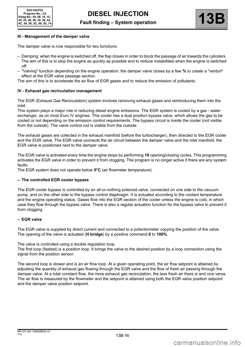
III - Management of the damper valve
The damper valve is now responsible for two functions:
– Damping: when the engine is switched off, the flap closes in order to block the passage of air towards the cylinders.
The aim of this is to stop the engine as quickly as possible and to reduce instabilities when the engine is switched
off.
– "Valving" function depending on the engine operation: the damper valve closes by a few % to create a "venturi"
effect at the EGR valve passage section.
The aim of this is to accelerate the air flow of EGR gases and to reduce the emission of pollutants.
IV - Exhaust gas recirculation management
The EGR (Exhaust Gas Recirculation) system involves removing exhaust gases and reintroducing them into the
inlet.
This system plays a major role in reducing diesel engine emissions. The EGR system is cooled by a gas - water
exchanger, as on most Euro IV engines. This cooler has a dual position bypass valve, which allows the gas to be
cooled or not depending on the emission control requirements. The bypass circuit is inside the cooler (not visible
from the outside). The valve control rod is visible from the outside.
The exhaust gases are collected in the exhaust manifold (before the turbocharger), then directed to the EGR cooler
and the EGR valve. The EGR valve connects the air circuit between the damper valve and the inlet manifold; the
EGR valve is positioned next to the damper valve.
The EGR valve is activated every time the engine stops by performing 10opening/closing cycles. This programming
activates the EGR valve in order to prevent it from clogging. The program is no longer active if there are any system
faults.
The EGR system does not operate below 5°C (air flowmeter temperature).
– The controlled EGR cooler bypass
The EGR cooler bypass is controlled by an all-or-nothing solenoid valve, connected on one side to the vacuum
pump, and on the other side to the bypass control diaphragm. It is actuated according to the coolant temperature
and the engine operating status. Gases flow into the EGR section of the cooler unless the engine is cold, in which
case they flow through the bypass valve. There is also a regular actuation function for the bypass valve to prevent it
from clogging.
– EGR valve
The EGR valve is supplied by direct current and connected to a potentiometer copying the position of the valve.
The opening of the valve is actuated (H bridge) by a positive command 0 to 100%.
The valve is controlled using a double regulation loop.
The first loop (fastest) is a position loop. It brings the valve to the desired position by a loop connection using the
signal from the position sensor.
The second loop is slower and is an air flow loop. At a given operating point, the air flow setpoint is attained by
adjusting the quantity of exhaust gas flowing through the EGR valve and the flow of fresh air passing through the
damper valve. At a total constant flow, the more exhaust gas recirculation, the less fresh air there is and vice versa.
The air flow is measured by the flowmeter and the setpoint is attained using both the EGR valve position setpoint
and the damper valve position setpoint.
Page 17 of 510
13B-17V12 MR-372-J84-13B300$030.mif
DIESEL INJECTION
Fault finding – System operation13B
EDC16CP33
Program No.: C4
Vdiag No.: 04, 08, 18, 1C,
20, 24, 26, 28, 34, 38, 44,
4C, 54, 58, 5C, 60, 62, 74
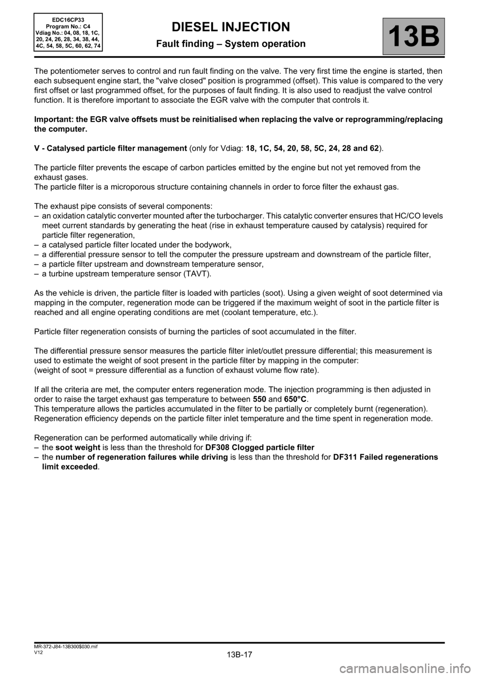
The potentiometer serves to control and run fault finding on the valve. The very first time the engine is started, then
each subsequent engine start, the "valve closed" position is programmed (offset). This value is compared to the very
first offset or last programmed offset, for the purposes of fault finding. It is also used to readjust the valve control
function. It is therefore important to associate the EGR valve with the computer that controls it.
Important: the EGR valve offsets must be reinitialised when replacing the valve or reprogramming/replacing
the computer.
V - Catalysed particle filter management (only for Vdiag: 18, 1C, 54, 20, 58, 5C, 24, 28 and 62).
The particle filter prevents the escape of carbon particles emitted by the engine but not yet removed from the
exhaust gases.
The particle filter is a microporous structure containing channels in order to force filter the exhaust gas.
The exhaust pipe consists of several components:
– an oxidation catalytic converter mounted after the turbocharger. This catalytic converter ensures that HC/CO levels
meet current standards by generating the heat (rise in exhaust temperature caused by catalysis) required for
particle filter regeneration,
– a catalysed particle filter located under the bodywork,
– a differential pressure sensor to tell the computer the pressure upstream and downstream of the particle filter,
– a particle filter upstream and downstream temperature sensor,
– a turbine upstream temperature sensor (TAVT).
As the vehicle is driven, the particle filter is loaded with particles (soot). Using a given weight of soot determined via
mapping in the computer, regeneration mode can be triggered if the maximum weight of soot in the particle filter is
reached and all engine operating conditions are met (coolant temperature, etc.).
Particle filter regeneration consists of burning the particles of soot accumulated in the filter.
The differential pressure sensor measures the particle filter inlet/outlet pressure differential; this measurement is
used to estimate the weight of soot present in the particle filter by mapping in the computer:
(weight of soot = pressure differential as a function of exhaust volume flow rate).
If all the criteria are met, the computer enters regeneration mode. The injection programming is then adjusted in
order to raise the target exhaust gas temperature to between 550 and 650°C.
This temperature allows the particles accumulated in the filter to be partially or completely burnt (regeneration).
Regeneration efficiency depends on the particle filter inlet temperature and the time spent in regeneration mode.
Regeneration can be performed automatically while driving if:
–the soot weight is less than the threshold for DF308 Clogged particle filter
–the number of regeneration failures while driving is less than the threshold for DF311 Failed regenerations
limit exceeded.
Page 204 of 510
13B-204
AFTER REPAIRDeal with any other faults. Clear the fault memory.
Switch off the ignition until the end of the power-latch phase, and carry out a road test
followed by a check with the diagnostic tool.
V12 MR-372-J84-13B300$074.mif
DIESEL INJECTION
Fault finding – Interpretation of faults13B
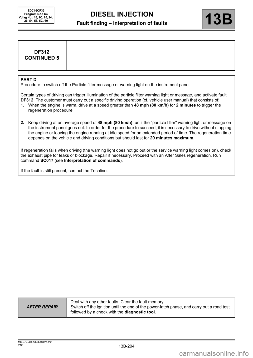
DF312
CONTINUED 5
PART D
Procedure to switch off the Particle filter message or warning light on the instrument panel
Certain types of driving can trigger illumination of the particle filter warning light or message, and activate fault
DF312. The customer must carry out a specific driving operation (cf. vehicle user manual) that consists of:
1. When the engine is warm, drive at a speed greater than 48 mph (80 km/h) for 2 minutes to trigger the
regeneration procedure.
2.Keep driving at an average speed of 48 mph (80 km/h), until the "particle filter" warning light or message on
the instrument panel goes out. In order for the procedure to succeed, it is necessary to drive without stopping
the engine or leaving the engine running at idle speed for an extended period of time. The regeneration time
depends on the vehicle and driving conditions but should last for 20 minutes maximum.
If regeneration fails when driving (the warning light does not go out or the service warning light comes on), check
the exhaust pipe for leaks or blockage. Repair if necessary. Proceed with an After Sales regeneration. Run
command SC017 (see Interpretation of commands).
If the fault is still present, contact the Techline.
EDC16CP33
Program No.: C4
Vdiag No.: 18, 1C, 20, 24,
26, 54, 58, 5C, 60