air filter RENAULT SCENIC 2012 J95 / 3.G Engine And Peripherals EDC16CP33 Workshop Manual
[x] Cancel search | Manufacturer: RENAULT, Model Year: 2012, Model line: SCENIC, Model: RENAULT SCENIC 2012 J95 / 3.GPages: 510, PDF Size: 2.98 MB
Page 3 of 510
13B-3V12 MR-372-J84-13B300$010.mif
DIESEL INJECTION
Fault finding – Introduction13B
EDC16CP33
Program No.: C4
Vdiag No.: 04, 08, 18, 1C,
20, 24, 26, 28, 34, 38, 44,
4C, 54, 58, 5C, 60, 62, 74
Faults
Faults are declared present or stored (depending on whether they appeared in a certain context and have
disappeared since, or whether they remain present but are not diagnosed within the current context).
The present or stored status of faults should be taken into consideration when the diagnostic tool is switched on
following + after ignition feed is activated (no system components active).
For a present fault, apply the procedure described in the Interpretation of faults section.
For a stored fault, note the faults displayed and apply the Notes section.
If the fault is confirmed when the instructions are applied, the fault is present. Deal with the fault.
If the fault is not confirmed, check:
– the electrical lines which correspond to the fault,
– the connectors on these lines (corrosion, bent pins, etc.),
– the resistance of the faulty component,
– the condition of the wires (melted or cut insulation, wear).
Conformity check
The purpose of the conformity check is to check data that does not produce a fault on the diagnostic tool if the data
is inconsistent. Therefore, this stage is used to:
– carry out fault finding on faults that do not have a fault display, and which may correspond to a customer complaint.
– check that the system is operating correctly and that there is no risk of a fault recurring after repair.
The conformity check is a fault finding procedure carried out using the interpretation of statuses and parameters.
If a status does not function normally or a parameter is outside the permitted tolerance values, consult the
corresponding fault finding pages (see interpretation of statuses and parameters).
Customer complaints - Fault finding chart
If the test with the diagnostic tool is correct but the customer complaint is still present, the fault should be dealt with
by customer complaints. WARNING:
Deal first with instrument panel faults (eg. "Particle filter" warning light).
Then carry out scheduled maintenance on the vehicle.
A synopsis of the general procedure to follow is provided on the following page in the form of a flow chart.
Page 8 of 510
13B-8V12 MR-372-J84-13B300$020.mif
13B
EDC16CP33
Program No.: C4
Vdiag No.: 04, 08, 18, 1C,
20, 24, 26, 28, 34, 38, 44,
4C, 54, 58, 5C, 60, 62, 74
I - HAZARDS ASSOCIATED WITH CONTAMINATION
The high pressure direct injection system is highly sensitive to contamination. The risks caused by the introduction of
contamination are:
– damage to or destruction of the high pressure injection system,
– a component seizing up,
– a component losing its sealing.
All After-Sales operations must be performed under very clean conditions. This means that no impurities
(particles a few microns in size) should have penetrated the system during dismantling.
The cleanliness guidelines must be applied from the filter through to the injectors.
What are the sources of contamination?
– metal or plastic swarf,
– paint,
–fibres:
– from cardboard,
– from brushes,
– from paper,
– from clothing,
– from cloths,
– foreign bodies such as hair,
– the ambient atmosphere
–etc.
IMPORTANT:
Cleaning the engine using a high pressure washer is prohibited because of the risk of damaging connections.
In addition, moisture may collect in the connectors and create faults in the electrical connections.
DIESEL INJECTION
Fault finding – Cleanliness guidelines
Page 11 of 510
13B-11V12 MR-372-J84-13B300$030.mif
13B
EDC16CP33
Program No.: C4
Vdiag No.: 04, 08, 18, 1C,
20, 24, 26, 28, 34, 38, 44,
4C, 54, 58, 5C, 60, 62, 74
System outline
The high pressure injection system is designed to deliver a precise quantity of diesel fuel to the engine at a set
moment.
It is fitted with a BOSCH computer, type EDC16CP33.
The system comprises:
– a priming bulb,
– a diesel filter,
– a high pressure pump,
– a fuel pressure regulator (or actuator) on the high pressure pump (MPROP),
– a fuel pressure regulator (or actuator) mounted on the injector rail (DRV),
– an injector rail,
– a fuel pressure sensor,
– four piezoelectric injectors,
– a diesel temperature sensor,
– a coolant temperature sensor,
– an upstream air temperature sensor,
– a cylinder reference sensor,
– an engine speed sensor,
– a turbocharger pressure sensor,
– an exhaust gas recirculation valve,
– a recycled gas cooling solenoid valve,
– an accelerator pedal potentiometer,
– an atmospheric pressure sensor integrated into the injection computer,
– a flow sensor,
– a turbocharging limiter solenoid valve,
– a damper valve,
– a particle filter,
– a turbo upstream temperature sensor,
– a turbo upstream pressure sensor,
– a particle filter differential pressure sensor,
– a particle filter upstream temperature sensor,
– a particle filter downstream temperature sensor,
– an electric coolant pump (turbocharger),
– four thermoplungers.
The common rail direct high pressure injection system works sequentially (based on the petrol engine
multipoint injection).
This system uses piezoelectric injectors which enable a more precise injection since opening and closing times
are shorter compared to conventional solenoid injectors.
This injection system reduces operating noise, reduces the volume of pollutant gases and particles and produces
high engine torque at low engine speeds thanks to a pre-injection procedure.
The high pressure pump generates the high pressure and transmits it to the injector rail. The actuator located on
the pump controls the quantity of diesel supplied, according to the demand determined by the computer.
The rail supplies each injector through a steel pipe. The actuator located on the injector rail controls the pressure
of diesel fuel in the rail according to the demand determined by the computer.
DIESEL INJECTION
Fault finding – System operation
Page 12 of 510
13B-12V12 MR-372-J84-13B300$030.mif
DIESEL INJECTION
Fault finding – System operation13B
EDC16CP33
Program No.: C4
Vdiag No.: 04, 08, 18, 1C,
20, 24, 26, 28, 34, 38, 44,
4C, 54, 58, 5C, 60, 62, 74
a. The computer:
Determines the injection pressure value necessary for the correct operation of the engine; the pressure can reach
1600 bar in the rail and it must be constantly regulated.
Checks that the pressure value is correct by analysing the value transmitted by the pressure sensor located on
the rail.
Determines the injection duration required to deliver the right quantity of diesel fuel and the moment when injection
should start. Controls each injector electrically and individually after determining these two values.
The quantity of fuel injected is determined by:
– Engine speed (Crankshaft + Cam for synchronisation).
– Accelerator pedal.
– Turbocharging pressure.
– Coolant temperature,
– Inlet air temperature.
–Air flow
– Pressure in the rail.
– Vehicle speed.
The computer manages:
– idling regulation,
– exhaust gas flow reinjection to the inlet,
– fuel supply check (advance, flow and rail pressure),
– the fan assembly control,
– the air conditioning (cold loop function),
– cruise control/speed limiter function,
– pre-post heating control,
– indicator lights control via the multiplex network,
– the operation of the catalysed particle filter,
– turbocharging pressure.
The high pressure pump is supplied at low pressure by an integrated low pressure pump (transfer pump).
It supplies the rail, the pressure in which is regulated by:
–the pressure regulator on the rail (DRV) for starting phases, starting the engine when cold (increase in
temperature to heat the diesel circuit) and when throttling-off,
–the pressure regulator on the pump (MPROP) for all other phases (90% of cases).
As natural leaks in piezoelectric injectors are very low, opening the pressure regulator (DRV) is the only quick
method of dumping the rail pressure and it prevents overpressure when injection is restarted.
The pressure regulator on the pump (MPROP) enables the high pressure pump to supply just the exact quantity
of diesel fuel required to maintain the rail pressure. This component minimises the heat generated and improves
engine output.
Note:
Each piezoelectric injector is connected to the return rail. The injector return rail is kept pressurised by a
mechanical valve at the end of the return rail with a 10 bar calibration (by comparison, solenoid injectors used to
return directly into the common fuel return circuit). This feature is linked to the operation of piezoelectric injectors.
Page 13 of 510
13B-13V12 MR-372-J84-13B300$030.mif
DIESEL INJECTION
Fault finding – System operation13B
EDC16CP33
Program No.: C4
Vdiag No.: 04, 08, 18, 1C,
20, 24, 26, 28, 34, 38, 44,
4C, 54, 58, 5C, 60, 62, 74
Fuel surplus from the pump, injector return rail or rail is collected in a low pressure "octopus manifold" and is then
sent to the fuel filter, providing that the fuel is cold (recirculation), and then to the tank.
The system can inject diesel fuel into the engine at a pressure of up to 1600 bar. Before each operation, check that
the injector rail is depressurised and that the fuel temperature is not too high.
You must respect the cleanliness guidelines and safety advice specified in this document for any work on the high
pressure injection system.
Removal of the internal parts of the pump and injectors is prohibited. Only the fuel pressure regulator (or actuator)
on the high pressure pump (MPROP), the fuel pressure regulator (or actuator) on the injector rail (DRV) or the diesel
temperature sensor can be replaced.
For safety reasons, it is strictly prohibited to undo a high pressure pipe union when the engine is running.
It is not possible to remove the pressure sensor from the fuel rail because this may cause circuit contamination
faults. If the pressure sensor fails, replace the pressure sensor, the rail and the high pressure pipes.
Some vehicles have a presence sensor mounted in the filter for detecting water in the diesel. If there is water in
the diesel fuel, the orange "Injection and pre-post heating" warning light will come on.
Supplying + 12 V directly to any component in the system is prohibited.
Ultrasonic decoking and cleaning are prohibited.
Never start the engine unless the battery is connected correctly.
Disconnect the injection computer when carrying out any welding work on the vehicle.
b. The connections between the vehicle's various computers are multiplexed.
The electronic system fitted in this vehicle is multiplexed.
This enables dialogue between the various vehicle computers. As a result:
– the fault warning lights on the instrument panel are lit by the multiplex network,
– vehicle faults are displayed by the multiplex network,
– the vehicle speed sensor on the gearbox is not needed.
The vehicle speed signal on the instrument panel is sent by the ABS computer via the multiplex network. The vehicle
speed signal is mainly used by the injection computer, the airbag computer and the automatic transmission
computer (if the vehicle is fitted with this).WARNING:
The engine must not operate with:
– Diesel fuel containing more than 10% diester,
– petrol, even in tiny quantities.
Note:
For the M9R 724 (Vdiag 5C and 58):
The engine is limited to 3000 rpm if the vehicle is stationary or if the vehicle speed is less than 4 mph (7 km/h)
and if the engine is warm.
Page 14 of 510
13B-14V12 MR-372-J84-13B300$030.mif
DIESEL INJECTION
Fault finding – System operation13B
EDC16CP33
Program No.: C4
Vdiag No.: 04, 08, 18, 1C,
20, 24, 26, 28, 34, 38, 44,
4C, 54, 58, 5C, 60, 62, 74
c. Functions hosted:
Air conditioning management assistance:
For vehicles with air conditioning, the EDC16CP33 system provides the option of deactivating the air conditioning
via the UCH, under certain conditions of use:
– when requested by the driver,
– when starting the engine,
– if the engine overheats (in order to reduce the power the engine has to supply),
– when the engine speed is kept at a very high level (to protect the compressor),
– during transition phases (e.g. under heavy acceleration when overtaking, anti-stalling and moving off strategies).
These conditions are only taken into account when they do not occur repeatedly, in order to prevent system
instabilities (erratic deactivations),
– when certain faults appear.
I - Cold loop air conditioning management:
The air conditioning is the cold loop type and its management shared between several computers.
The injection computer is responsible for:
– authorising requests for cold air depending on the engine coolant temperature and the engine speed,
– calculating the power absorbed by the compressor from the refrigerant pressure.
–requesting fan assembly actuation (Mégane II ph2 and Scénic II ph2) and controlling fan assembly actuation
(Laguna II, Vel Satis ph2 and Espace IV ph2), according to the vehicle speed, the refrigerant pressure and the
engine coolant temperature.
The driver requests the air conditioning to be switched on by means of the ventilation selector coupled to a switch.
The cold air request is authorised or denied depending on the pressure measured. If this pressure is outside the
operating limits, the cold loop program is not activated.
The air conditioning system is authorised by the injection computer 2 to 8 seconds after the engine is started.
Management of the thermoplungers:
To improve cold starting, the vehicle is fitted with thermoplungers. These thermoplungers are managed and
controlled by the injection computer, according to the operating phases, primarily to accelerate the increase in
engine coolant temperature.
The maximum number of thermoplungers that can be actuated is four and their actuation depends mainly on the
coolant temperature and the air temperature.
See configuration reading LC056 Thermoplungers: WITH or WITHOUT.
When necessary, they are actuated by the injection system only during particle filter regeneration by means
of a special unit.
The maximum number of thermoplungers that can be managed is four and their activation depends mainly on the
coolant temperature (< 15°C) and air temperature (< 5°C).
Page 19 of 510
13B-19V12 MR-372-J84-13B300$030.mif
DIESEL INJECTION
Fault finding – System operation13B
EDC16CP33
Program No.: C4
Vdiag No.: 04, 08, 18, 1C,
20, 24, 26, 28, 34, 38, 44,
4C, 54, 58, 5C, 60, 62, 74
Warning light management:
Instrument panel display
The computer displays certain information on the instrument panel relating to engine operation. This concerns five
functions:
– the pre-postheating warning light,
– the coolant temperature warning light,
–the level 1 fault warning light (non-critical fault),
–the level 2 fault warning light (emergency stop),
–the EOBD (European On Board Diagnostic) warning light,
These six functions are represented by 3 warning lights and/or messages displayed by the on-board computer.
Orange pre-post heating/non-critical fault SERVICE warning light (severity 1)
This light is used both as an in-operation indicator light and as a system fault indicator:
– Continuously lit with + after ignition feed:
Indicates preheating of the spark plugs.
– Continuously lit with the Check injection message:
Indicates a level 1 fault (involving operation of the injection system in defect mode).
The driver should have the repairs carried out as soon as possible.
Temperature / red emergency STOP warning light (level 2)
This indicator light is used both as an in-operation indicator light and as a system fault warning light. It lights up for
3 seconds after the ignition is switched on (automatic test procedure managed by the instrument panel):
– Continuously lit:
Indicates engine overheating (the driver is free to choose whether or not to stop the vehicle).
– Continuously lit with the faulty injection message:
Indicates a level 2 fault (In this case, the injection is automatically cut after a few seconds).
The driver should carry out repairs as soon as possible.
ORANGE Excessive pollution EOBD warning light
Symbolised by an engine, it lights up for approximately 3 seconds when the ignition is switched on.
This warning light comes on if the system has one or more EOBD faults.
This warning light is used to alert the driver to injection faults that could lead to excessive pollution, or if the EOBD
system (European On Board Diagnostic) has been deactivated.
The injection computer requests illumination of the EOBD warning light for a present fault only after three
consecutive driving cycles.
The 3 second visual inspection when the ignition is switched on (automatic test procedure managed by the
instrument panel) is carried out by the injection computer.
Special particle filter ORANGE warning light or warning message (depending on instrument panel)
Only for Vdiag: 18, 1C, 54, 20, 58, 5C, 24, 26 and 60.
This warning light or message is used to warn the driver that the particle filter is loaded with particles, (see the soot
weight thresholds for illumination of the warning light for fault DF312 Speed request) due to driving conditions which
were not suitable for regeneration to take place. The driver must then drive as soon as possible at an average speed
of 48 mph (80 km/h) subject to the road conditions and authorised speed limits, until the warning light goes out.
Page 22 of 510
13B-22V12 MR-372-J84-13B300$050.mif
13B
EDC16CP33
Program No.: C4
Vdiag No.: 04, 08, 18, 1C,
20, 24, 26, 28, 34, 38, 44,
4C, 54, 58, 5C, 60, 62, 74
COMPUTER REPLACEMENT OR REPROGRAMMING
Two operations must be performed when replacing or reprogramming the computer:
SC003 Save computer data and SC001 Enter saved data.
–Run SC003 before replacing or reprogramming the computer. This enables certain data to be saved in the
diagnostic tool so that the new computer* can be reconfigured like the old one. The saved data includes: injector
codes, EGR programming, specific data for particle filter operation and vehicle options.
–Run SC001 after replacing or reprogramming the computer. It enables you to rewrite the data (saved by
command SC003) to the new computer*.
Only Vdiag 20, 24, 38 and 74:
–Run SC036 Reinitialise programming and select Heater plugs (see Interpretation of commands); this will allow
you to configure the correct type of heater plugs fitted on the vehicle, if necessary.
If you cannot establish dialogue with the computer being replaced: you will not be able to save anything. After
replacing the computer:
– Write the IMA codes for each injector manually by reading the code on each injector; run command SC002 Enter
injector codes.
– Check the exhaust pipe for leaks or blockage. Repair if necessary.
– Perform an After-Sales regeneration, follow the procedure for command SC017 Particle filter regeneration (see
Interpretation of commands).
– It is essential to change the engine oil and oil filter.
– Enter the data specific to particle filter operation by running SC036 Reinitialise programming and selecting after
replacing injection computer with no save option.
– Enter the VIN into the computer, use command VP010 Enter VIN.
–Only for Vdiag 20, 24, 38 and 74: Configure the type of heater plugs fitted on the vehicle by running SC036
Reinitialise programming and selecting Heater plugs (see Interpretation of commands).
Exhaust gas recirculation valve data is programmed automatically the 1st time the new computer is turned on*.
* New computer or reprogrammed computer.
IMA*: Individual injector correctionOperations to be carried out before the injection computer is reprogrammed:
Before reprogramming the injection computer, move the main cruise control/speed limiter switch to the rest
position. The information about the cruise control or the speed limiter displayed on the instrument panel
disappears.
Otherwise, if the main switch remains in the cruise control or speed limiter position during and after reprogramming,
the cruise control/speed limiter function will not be operational.
The procedure for resetting the function is as follows:
Vehicle ignition on.
• Position the cruise control/speed limiter switch in the rest position (the computer detects the rest position at that
moment).
• Position the cruise control/speed limiter switch in the Cruise control position to activate the cruise control
function.
• Position the cruise control/speed limiter switch in the Speed limiter position to activate the speed limiter function.
DIESEL INJECTION
Fault finding – Replacement of components
Page 30 of 510
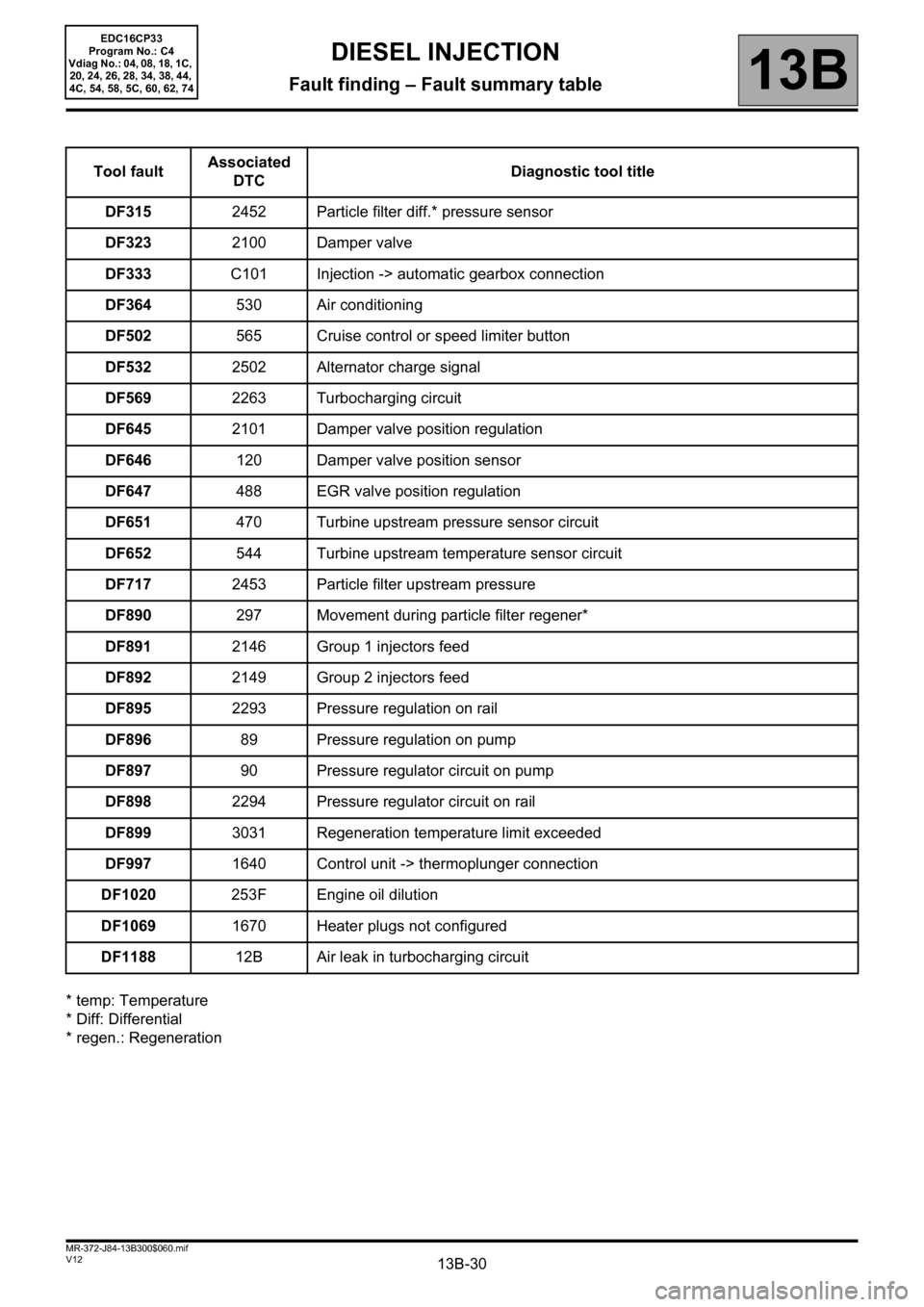
13B-30V12 MR-372-J84-13B300$060.mif
DIESEL INJECTION
Fault finding – Fault summary table13B
EDC16CP33
Program No.: C4
Vdiag No.: 04, 08, 18, 1C,
20, 24, 26, 28, 34, 38, 44,
4C, 54, 58, 5C, 60, 62, 74
* temp: Temperature
* Diff: Differential
* regen.: RegenerationTool faultAssociated
DTCDiagnostic tool title
DF3152452 Particle filter diff.* pressure sensor
DF3232100 Damper valve
DF333C101 Injection -> automatic gearbox connection
DF364530 Air conditioning
DF502565 Cruise control or speed limiter button
DF5322502 Alternator charge signal
DF5692263 Turbocharging circuit
DF6452101 Damper valve position regulation
DF646120 Damper valve position sensor
DF647488 EGR valve position regulation
DF651470 Turbine upstream pressure sensor circuit
DF652544 Turbine upstream temperature sensor circuit
DF7172453 Particle filter upstream pressure
DF890297 Movement during particle filter regener*
DF8912146 Group 1 injectors feed
DF8922149 Group 2 injectors feed
DF8952293 Pressure regulation on rail
DF89689 Pressure regulation on pump
DF89790 Pressure regulator circuit on pump
DF8982294 Pressure regulator circuit on rail
DF8993031 Regeneration temperature limit exceeded
DF9971640 Control unit -> thermoplunger connection
DF1020253F Engine oil dilution
DF10691670 Heater plugs not configured
DF118812B Air leak in turbocharging circuit
Page 38 of 510
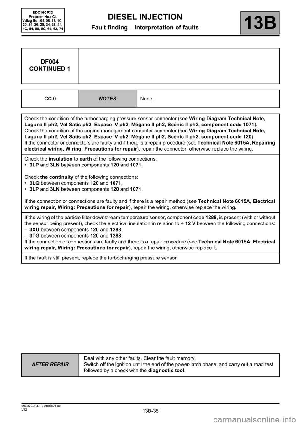
13B-38
AFTER REPAIRDeal with any other faults. Clear the fault memory.
Switch off the ignition until the end of the power-latch phase, and carry out a road test
followed by a check with the diagnostic tool.
V12 MR-372-J84-13B300$071.mif
DIESEL INJECTION
Fault finding – Interpretation of faults13B
EDC16CP33
Program No.: C4
Vdiag No.: 04, 08, 18, 1C,
20, 24, 26, 28, 34, 38, 44,
4C, 54, 58, 5C, 60, 62, 74
DF004
CONTINUED 1
CC.0NOTESNone.
Check the condition of the turbocharging pressure sensor connector (see Wiring Diagram Technical Note,
Laguna II ph2, Vel Satis ph2, Espace IV ph2, Mégane II ph2, Scénic II ph2, component code 1071).
Check the condition of the engine management computer connector (see Wiring Diagram Technical Note,
Laguna II ph2, Vel Satis ph2, Espace IV ph2, Mégane II ph2, Scénic II ph2, component code 120).
If the connector or connectors are faulty and if there is a repair procedure (see Technical Note 6015A, Repairing
electrical wiring, Wiring: Precautions for repair), repair the connector, otherwise replace the wiring.
Check the insulation to earth of the following connections:
•3LP and 3LN between components 120 and 1071.
Check the continuity of the following connections:
•3LQ between components 120 and 1071,
•3LP and 3LN between components 120 and 1071.
If the connection or connections are faulty and if there is a repair method (see Technical Note 6015A, Electrical
wiring repair, Wiring: Precautions for repair), repair the wiring, otherwise replace the wiring.
If the wiring of the particle filter downstream temperature sensor, component code 1288, is present (with or without
the sensor being present), check the electrical insulation in relation to + 12 V between the following connections:
–3XU between components 120 and 1288,
–3TG between components 120 and 1288.
If the connection or connections are faulty and there is a repair procedure (see Technical Note 6015A, Electrical
wiring repair, Wiring: Precautions for repair), repair the wiring, otherwise replace it.
If the fault is still present, replace the turbocharging pressure sensor.