downstream RENAULT SCENIC 2012 J95 / 3.G Engine And Peripherals EDC16CP33 Workshop Manual
[x] Cancel search | Manufacturer: RENAULT, Model Year: 2012, Model line: SCENIC, Model: RENAULT SCENIC 2012 J95 / 3.GPages: 510, PDF Size: 2.98 MB
Page 11 of 510
13B-11V12 MR-372-J84-13B300$030.mif
13B
EDC16CP33
Program No.: C4
Vdiag No.: 04, 08, 18, 1C,
20, 24, 26, 28, 34, 38, 44,
4C, 54, 58, 5C, 60, 62, 74
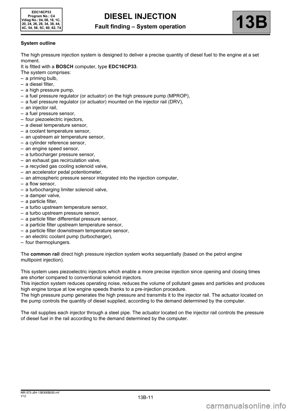
System outline
The high pressure injection system is designed to deliver a precise quantity of diesel fuel to the engine at a set
moment.
It is fitted with a BOSCH computer, type EDC16CP33.
The system comprises:
– a priming bulb,
– a diesel filter,
– a high pressure pump,
– a fuel pressure regulator (or actuator) on the high pressure pump (MPROP),
– a fuel pressure regulator (or actuator) mounted on the injector rail (DRV),
– an injector rail,
– a fuel pressure sensor,
– four piezoelectric injectors,
– a diesel temperature sensor,
– a coolant temperature sensor,
– an upstream air temperature sensor,
– a cylinder reference sensor,
– an engine speed sensor,
– a turbocharger pressure sensor,
– an exhaust gas recirculation valve,
– a recycled gas cooling solenoid valve,
– an accelerator pedal potentiometer,
– an atmospheric pressure sensor integrated into the injection computer,
– a flow sensor,
– a turbocharging limiter solenoid valve,
– a damper valve,
– a particle filter,
– a turbo upstream temperature sensor,
– a turbo upstream pressure sensor,
– a particle filter differential pressure sensor,
– a particle filter upstream temperature sensor,
– a particle filter downstream temperature sensor,
– an electric coolant pump (turbocharger),
– four thermoplungers.
The common rail direct high pressure injection system works sequentially (based on the petrol engine
multipoint injection).
This system uses piezoelectric injectors which enable a more precise injection since opening and closing times
are shorter compared to conventional solenoid injectors.
This injection system reduces operating noise, reduces the volume of pollutant gases and particles and produces
high engine torque at low engine speeds thanks to a pre-injection procedure.
The high pressure pump generates the high pressure and transmits it to the injector rail. The actuator located on
the pump controls the quantity of diesel supplied, according to the demand determined by the computer.
The rail supplies each injector through a steel pipe. The actuator located on the injector rail controls the pressure
of diesel fuel in the rail according to the demand determined by the computer.
DIESEL INJECTION
Fault finding – System operation
Page 17 of 510
13B-17V12 MR-372-J84-13B300$030.mif
DIESEL INJECTION
Fault finding – System operation13B
EDC16CP33
Program No.: C4
Vdiag No.: 04, 08, 18, 1C,
20, 24, 26, 28, 34, 38, 44,
4C, 54, 58, 5C, 60, 62, 74
The potentiometer serves to control and run fault finding on the valve. The very first time the engine is started, then
each subsequent engine start, the "valve closed" position is programmed (offset). This value is compared to the very
first offset or last programmed offset, for the purposes of fault finding. It is also used to readjust the valve control
function. It is therefore important to associate the EGR valve with the computer that controls it.
Important: the EGR valve offsets must be reinitialised when replacing the valve or reprogramming/replacing
the computer.
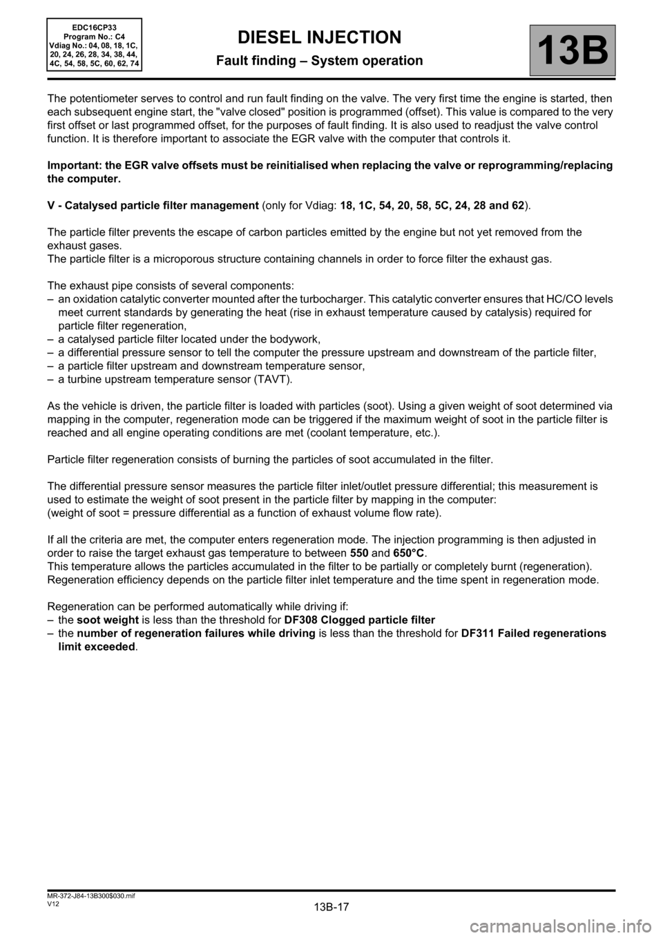
V - Catalysed particle filter management (only for Vdiag: 18, 1C, 54, 20, 58, 5C, 24, 28 and 62).
The particle filter prevents the escape of carbon particles emitted by the engine but not yet removed from the
exhaust gases.
The particle filter is a microporous structure containing channels in order to force filter the exhaust gas.
The exhaust pipe consists of several components:
– an oxidation catalytic converter mounted after the turbocharger. This catalytic converter ensures that HC/CO levels
meet current standards by generating the heat (rise in exhaust temperature caused by catalysis) required for
particle filter regeneration,
– a catalysed particle filter located under the bodywork,
– a differential pressure sensor to tell the computer the pressure upstream and downstream of the particle filter,
– a particle filter upstream and downstream temperature sensor,
– a turbine upstream temperature sensor (TAVT).
As the vehicle is driven, the particle filter is loaded with particles (soot). Using a given weight of soot determined via
mapping in the computer, regeneration mode can be triggered if the maximum weight of soot in the particle filter is
reached and all engine operating conditions are met (coolant temperature, etc.).
Particle filter regeneration consists of burning the particles of soot accumulated in the filter.
The differential pressure sensor measures the particle filter inlet/outlet pressure differential; this measurement is
used to estimate the weight of soot present in the particle filter by mapping in the computer:
(weight of soot = pressure differential as a function of exhaust volume flow rate).
If all the criteria are met, the computer enters regeneration mode. The injection programming is then adjusted in
order to raise the target exhaust gas temperature to between 550 and 650°C.
This temperature allows the particles accumulated in the filter to be partially or completely burnt (regeneration).
Regeneration efficiency depends on the particle filter inlet temperature and the time spent in regeneration mode.
Regeneration can be performed automatically while driving if:
–the soot weight is less than the threshold for DF308 Clogged particle filter
–the number of regeneration failures while driving is less than the threshold for DF311 Failed regenerations
limit exceeded.
Page 29 of 510
13B-29V12 MR-372-J84-13B300$060.mif
DIESEL INJECTION
Fault finding – Fault summary table13B
EDC16CP33
Program No.: C4
Vdiag No.: 04, 08, 18, 1C,
20, 24, 26, 28, 34, 38, 44,
4C, 54, 58, 5C, 60, 62, 74
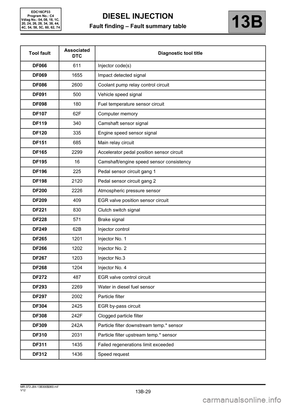
Tool faultAssociated
DTCDiagnostic tool title
DF066611 Injector code(s)
DF0691655 Impact detected signal
DF0862600 Coolant pump relay control circuit
DF091500 Vehicle speed signal
DF098180 Fuel temperature sensor circuit
DF10762F Computer memory
DF119340 Camshaft sensor signal
DF120335 Engine speed sensor signal
DF151685 Main relay circuit
DF1652299 Accelerator pedal position sensor circuit
DF19516 Camshaft/engine speed sensor consistency
DF196225 Pedal sensor circuit gang 1
DF1982120 Pedal sensor circuit gang 2
DF2002226 Atmospheric pressure sensor
DF209409 EGR valve position sensor circuit
DF221830 Clutch switch signal
DF228571 Brake signal
DF24962B Injector control
DF2651201 Injector No. 1
DF2661202 Injector No. 2
DF2671203 Injector No.3
DF2681204 Injector No. 4
DF272487 EGR valve control circuit
DF2932269 Water in diesel fuel sensor
DF2972002 Particle filter
DF3042425 EGR by-pass circuit
DF308242F Clogged particle filter
DF309242A Particle filter downstream temp.* sensor
DF3102031 Particle filter upstream temp.* sensor
DF3111435 Failed regenerations limit exceeded
DF3121436 Speed request
Page 38 of 510
13B-38
AFTER REPAIRDeal with any other faults. Clear the fault memory.
Switch off the ignition until the end of the power-latch phase, and carry out a road test
followed by a check with the diagnostic tool.
V12 MR-372-J84-13B300$071.mif
DIESEL INJECTION
Fault finding – Interpretation of faults13B
EDC16CP33
Program No.: C4
Vdiag No.: 04, 08, 18, 1C,
20, 24, 26, 28, 34, 38, 44,
4C, 54, 58, 5C, 60, 62, 74
DF004
CONTINUED 1
CC.0NOTESNone.
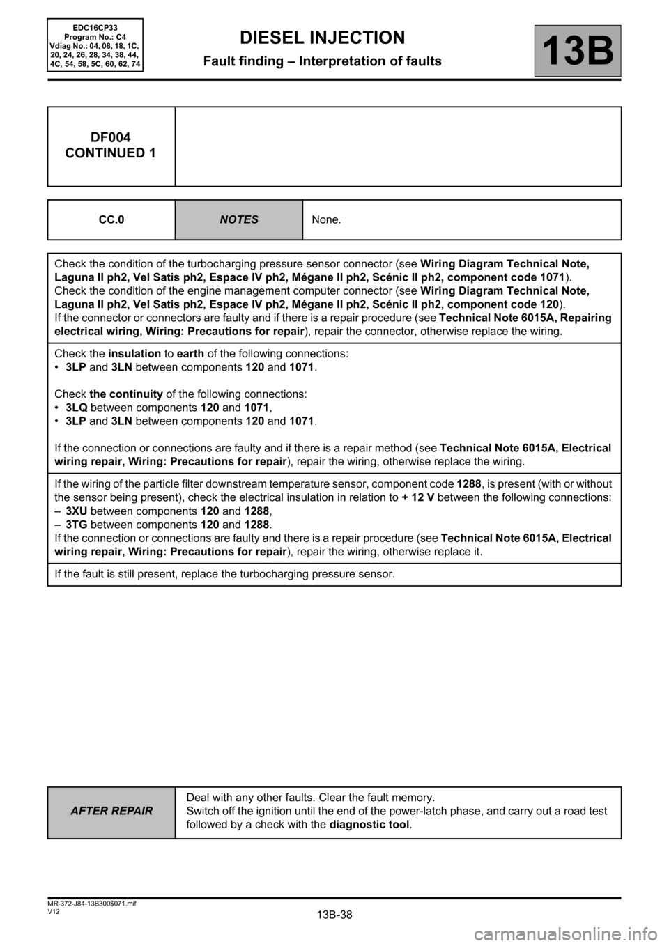
Check the condition of the turbocharging pressure sensor connector (see Wiring Diagram Technical Note,
Laguna II ph2, Vel Satis ph2, Espace IV ph2, Mégane II ph2, Scénic II ph2, component code 1071).
Check the condition of the engine management computer connector (see Wiring Diagram Technical Note,
Laguna II ph2, Vel Satis ph2, Espace IV ph2, Mégane II ph2, Scénic II ph2, component code 120).
If the connector or connectors are faulty and if there is a repair procedure (see Technical Note 6015A, Repairing
electrical wiring, Wiring: Precautions for repair), repair the connector, otherwise replace the wiring.
Check the insulation to earth of the following connections:
•3LP and 3LN between components 120 and 1071.
Check the continuity of the following connections:
•3LQ between components 120 and 1071,
•3LP and 3LN between components 120 and 1071.
If the connection or connections are faulty and if there is a repair method (see Technical Note 6015A, Electrical
wiring repair, Wiring: Precautions for repair), repair the wiring, otherwise replace the wiring.
If the wiring of the particle filter downstream temperature sensor, component code 1288, is present (with or without
the sensor being present), check the electrical insulation in relation to + 12 V between the following connections:
–3XU between components 120 and 1288,
–3TG between components 120 and 1288.
If the connection or connections are faulty and there is a repair procedure (see Technical Note 6015A, Electrical
wiring repair, Wiring: Precautions for repair), repair the wiring, otherwise replace it.
If the fault is still present, replace the turbocharging pressure sensor.
Page 41 of 510

13B-41
AFTER REPAIRDeal with any other faults. Clear the fault memory.
Switch off the ignition until the end of the power-latch phase, and carry out a road test
followed by a check with the diagnostic tool.
V12 MR-372-J84-13B300$071.mif
DIESEL INJECTION
Fault finding – Interpretation of faults13B
EDC16CP33
Program No.: C4
Vdiag No.: 04, 08, 18, 1C,
20, 24, 26, 28, 34, 38, 44,
4C, 54, 58, 5C, 60, 62, 74
DF007
CONTINUED 1
CC.0NOTESNone.
Check the condition of the rail pressure sensor connector (see Wiring Diagram Technical Note, Laguna II ph2,
Vel Satis ph2, Espace IV ph2, Mégane II ph2, Scénic II ph2, component code 1032).
Check the condition of the engine management computer connector (see Wiring Diagram Technical Note,
Laguna II ph2, Vel Satis ph2, Espace IV ph2, Mégane II ph2, Scénic II ph2, component code 120).
If the connector or connectors are faulty and if there is a repair procedure (see Technical Note 6015A, Electrical
wiring repair, Wiring: Precautions for repair), repair the connector, otherwise replace the wiring.
Check the continuity of the following connection:
•3LX between components 120 and 1032.
Check the insulation to earth of the following connection:
•3LY between components 120 and 1032.
If the connection or connections are faulty and there is a repair procedure (see Technical Note 6015A, Electrical
wiring repair, Wiring: Precautions for repair), repair the wiring, otherwise replace it.
If the wiring of the particle filter downstream temperature sensor, component code 1288, is present (with or without
the sensor being present), check the electrical insulation in relation to + 12 V between the following connections:
–3XU between components 120 and 1288,
–3TG between components 120 and 1288.
If the connection or connections are faulty and there is a repair procedure (see Technical Note 6015A, Electrical
wiring repair, Wiring: Precautions for repair), repair the wiring, otherwise replace it.
If the fault is still present, contact the Techline.
Page 107 of 510
13B-107
AFTER REPAIRDeal with any other faults. Clear the fault memory.
Switch off the ignition until the end of the power-latch phase, and carry out a road test
followed by a check with the diagnostic tool.
V12 MR-372-J84-13B300$072.mif
DIESEL INJECTION
Fault finding – Interpretation of faults13B
EDC16CP33
Program No.: C4
Vdiag No.: 04, 08, 18, 1C,
20, 24, 26, 28, 34, 38, 44,
4C, 54, 58, 5C, 60, 62, 74
DF051
STOREDCRUISE CONTROL/SPEED LIMITER1.DEF: Cruise control/speed limiter steering wheel control
NOTESPriority when dealing with a number of faults:
– DF196 Pedal sensor circuit gang 1
– DF198 Pedal sensor circuit gang 2.
Conditions for applying the fault finding procedure to a stored fault:
If the fault is declared present after:
– a road test with activation of the cruise control/speed limiter function,
– the engine is started.
Special notes:
If the fault is present:
– the cruise control/speed limiter function is switched off.
Use bornier Elé. 1681 for any operations on the injection computer connectors.
Use the Wiring Diagram Technical Note, Laguna II ph2, Vel Satis ph2, Espace IV
ph2, Mégane II ph2, Scénic II ph2.
If the wiring of the particle filter downstream temperature sensor, component code 1288, is present (with or without
the sensor being present), check the electrical insulation in relation to + 12 V between the following connections:
–3XU between components 120 and 1288,
–3TG between components 120 and 1288.
If the connection or connections are faulty and there is a repair procedure (see Technical Note 6015A, Electrical
wiring repair, Wiring: Precautions for repair), repair the wiring, otherwise replace it.
EDC16CP33_V18_DF051M / EDC16CP33_V1C_DF051M / EDC16CP33_V54_DF051M / EDC16CP33_V20_DF051M /
EDC16CP33_V58_DF051M / EDC16CP33_V5C_DF051M / EDC16CP33_V24_DF051M / EDC16CP33_V04_DF051M /
EDC16CP33_V08_DF051M / EDC16CP33_V44_DF051M / EDC16CP33_V4C_DF051M / EDC16CP33_V34_DF051M /
EDC16CP33_V38_DF051M / EDC16CP33_V74_DF051M / EDC16CP33_V28_DF051M / EDC16CP33_V62_DF051M /
EDC16CP33_V26_DF051M / EDC16CP33_V60_DF051M
Page 138 of 510
13B-138
AFTER REPAIRDeal with any other faults. Clear the fault memory.
Switch off the ignition until the end of the power-latch phase, and carry out a road test
followed by a check with the diagnostic tool.
V12 MR-372-J84-13B300$072.mif
DIESEL INJECTION
Fault finding – Interpretation of faults13B
EDC16CP33
Program No.: C4
Vdiag No.: 04, 08, 18, 1C,
20, 24, 26, 28, 34, 38, 44,
4C, 54, 58, 5C, 60, 62, 74
DF098
CONTINUED
CO.1NOTESNone.
If the wiring of the particle filter downstream temperature sensor, component code 1288, is present (with or without
the sensor being present), check the electrical insulation in relation to + 12 V between the following connections:
–3XU between components 120 and 1288,
–3TG between components 120 and 1288.
If the connection or connections are faulty and there is a repair procedure (see Technical Note 6015A, Electrical
wiring repair, Wiring: Precautions for repair), repair the wiring, otherwise replace it.
Check the condition of the fuel temperature sensor connector (see Wiring Diagram Technical Note, Laguna II
ph2, Vel Satis ph2, Espace IV ph2, Mégane II ph2, Scénic II ph2, component code 1066).
Check the condition of the engine management computer connector (see Wiring Diagram Technical Note,
Laguna II ph2, Vel Satis ph2, Espace IV ph2, Mégane II ph2, Scénic II ph2, component code 120).
If the connector or connectors are faulty and if there is a repair procedure (see Technical Note 6015A, Repairing
electrical wiring, Wiring: Precautions for repair), repair the connector, otherwise replace the wiring.
Measure the resistance between connections 3FAB and 3LD of component 1066.
Replace the fuel temperature sensor if its resistance is less than 85 Ω or greater than 50 kΩ.
Check the continuity of the following connections:
•3FAB between components 120 and 1066,
•3LD between components 120 and 1066.
Check the insulation in relation to +12 V of the following connection:
•3FAB between components 120 and 1066.
If the connection or connections are faulty and if there is a repair method (see Technical Note 6015A, Electrical
wiring repair, Wiring: Precautions for repair), repair the wiring, otherwise replace the wiring.
Page 191 of 510
13B-191
AFTER REPAIRDeal with any other faults. Clear the fault memory.
Switch off the ignition until the end of the power-latch phase, and carry out a road test
followed by a check with the diagnostic tool.
V12 MR-372-J84-13B300$073.mif
DIESEL INJECTION
Fault finding – Interpretation of faults13B
diff.*: Differential
temp.*: Temperature
DF308
PRESENT
OR
STOREDCLOGGED PARTICLE FILTER
1.DEF: Maximum limit
NOTESConditions for applying fault finding procedures to stored faults:
The fault is declared present after the engine is started or following a road test.
Special notes:
If the fault is present:
– particle filter regeneration is inhibited,
– the EGR function is inhibited,
– the vehicle performance is reduced,
–the level 1 warning light is lit and a warning message (or warning light) is displayed
on the instrument panel,
–the EOBD (European On Board Diagnostic) warning light is lit (except Vdiag 18,
1C, 24 and 54).
Priorities when dealing with a number of faults:
Deal with the following faults first:
– DF315 Particle filter differential pressure sensor if it is present.
– DF308 if DF315 is stored.
– DF717 Particle filter upstream pressure if it is present or stored.
– DF645 Damper valve position regulation if it is present or stored.
– DF272 EGR valve control circuit if it is present or stored.
– DF647 EGR valve position regulation if it is present or stored.
– DF309 Particle filter downstream temperature sensor if it is present or stored.
– DF899 Regeneration temperature threshold exceeded if it is present or stored.
– DF310 Particle filter upstream temperature sensor if it is present or stored.
– DF652 Turbine upstream temperature sensor circuit if it is present or stored.
EDC16CP33_V18_DF308 / EDC16CP33_V1C_DF308 / EDC16CP33_V54_DF308 / EDC16CP33_V20_DF308 / EDC16CP33_V58_DF308 /
EDC16CP33_V5C_DF308 / EDC16CP33_V24_DF308 / EDC16CP33_V28_DF308 / EDC16CP33_V62_DF308 / EDC16CP33_V26_DF308 /
EDC16CP33_V60_DF308
EDC16CP33
Program No.: C4
Vdiag No.: 18, 1C, 20, 24,
26, 28, 54, 58, 5C, 60, 62
Page 193 of 510
13B-193
AFTER REPAIRDeal with any other faults. Clear the fault memory.
Switch off the ignition until the end of the power-latch phase, and carry out a road test
followed by a check with the diagnostic tool.
V12 MR-372-J84-13B300$073.mif
DIESEL INJECTION
Fault finding – Interpretation of faults13B
DF309
PRESENT
OR
STOREDPARTICLE FILT. DOWNSTREAM TEMP. SENSOR
CC.0: Short circuit to earth
CO.1: Open circuit or short circuit to +12 V
NOTESConditions for applying fault finding procedures to stored faults:
The fault becomes present if:
– ignition is on (CC.0),
– following a road test, engine warm (CO.1).
IMPORTANT:
The particle filter downstream temperature sensor only measures temperatures
greater than 50°C.
Special notes:
– If the fault is present:
– After-Sales particle filter regeneration is inhibited,
– particle filter fault finding is inhibited (for Vdiags 18, 1C and 54).
CC.0
NOTESNone.
Check the condition of the particle filter downstream temperature sensor connector (see Wiring Diagram
Technical Note, Laguna II ph2, Vel Satis ph2, Espace IV ph2, Mégane II ph2, Scénic II ph2, component code
1288).
Check the condition of the engine management computer connector (see Wiring Diagram Technical Note,
Laguna II ph2, Vel Satis ph2, Espace IV ph2, Mégane II ph2, Scénic II ph2, component code 120).
If the connector or connectors are faulty and if there is a repair procedure (see Technical Note 6015A, Repairing
electrical wiring, Wiring: Precautions for repair), repair the connector, otherwise replace the wiring.
Check the insulation from earth of the following connections:
•3TG between components 120 and 1288,
•3XU between components 120 and 1288.
If the connection or connections are faulty and if there is a repair method (see Technical Note 6015A, Electrical
wiring repair, Wiring: Precautions for repair), repair the wiring, otherwise replace the wiring.
If the fault is still present, replace the particle filter downstream temperature sensor.
EDC16CP33_V18_DF309 / EDC16CP33_V1C_DF309 / EDC16CP33_V54_DF309 / EDC16CP33_V20_DF309 / EDC16CP33_V58_DF309 /
EDC16CP33_V5C_DF309 / EDC16CP33_V24_DF309 / EDC16CP33_V60_DF309 / EDC16CP33_V62_DF309
EDC16CP33
Program No.: C4
Vdiag No.: 18, 1C, 20, 24,
54, 58, 5C, 60, 62
Page 194 of 510
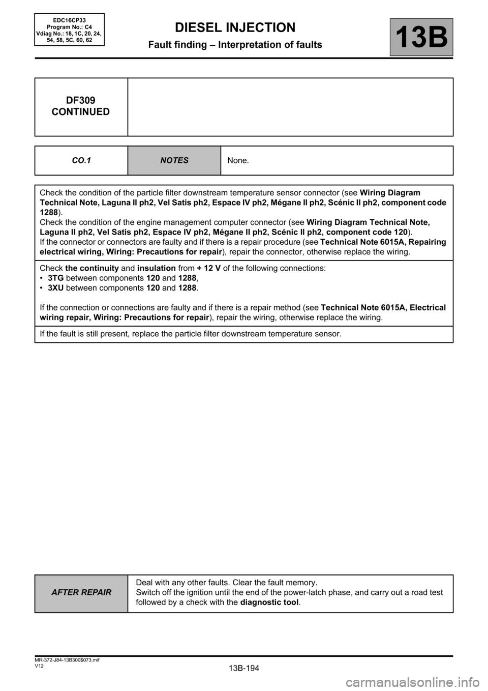
13B-194
AFTER REPAIRDeal with any other faults. Clear the fault memory.
Switch off the ignition until the end of the power-latch phase, and carry out a road test
followed by a check with the diagnostic tool.
V12 MR-372-J84-13B300$073.mif
DIESEL INJECTION
Fault finding – Interpretation of faults13B
DF309
CONTINUED
CO.1NOTESNone.
Check the condition of the particle filter downstream temperature sensor connector (see Wiring Diagram
Technical Note, Laguna II ph2, Vel Satis ph2, Espace IV ph2, Mégane II ph2, Scénic II ph2, component code
1288).
Check the condition of the engine management computer connector (see Wiring Diagram Technical Note,
Laguna II ph2, Vel Satis ph2, Espace IV ph2, Mégane II ph2, Scénic II ph2, component code 120).
If the connector or connectors are faulty and if there is a repair procedure (see Technical Note 6015A, Repairing
electrical wiring, Wiring: Precautions for repair), repair the connector, otherwise replace the wiring.
Check the continuity and insulation from + 12 V of the following connections:
•3TG between components 120 and 1288,
•3XU between components 120 and 1288.
If the connection or connections are faulty and if there is a repair method (see Technical Note 6015A, Electrical
wiring repair, Wiring: Precautions for repair), repair the wiring, otherwise replace the wiring.
If the fault is still present, replace the particle filter downstream temperature sensor.
EDC16CP33
Program No.: C4
Vdiag No.: 18, 1C, 20, 24,
54, 58, 5C, 60, 62