downstream RENAULT SCENIC 2012 J95 / 3.G Engine And Peripherals EDC16CP33 User Guide
[x] Cancel search | Manufacturer: RENAULT, Model Year: 2012, Model line: SCENIC, Model: RENAULT SCENIC 2012 J95 / 3.GPages: 510, PDF Size: 2.98 MB
Page 196 of 510
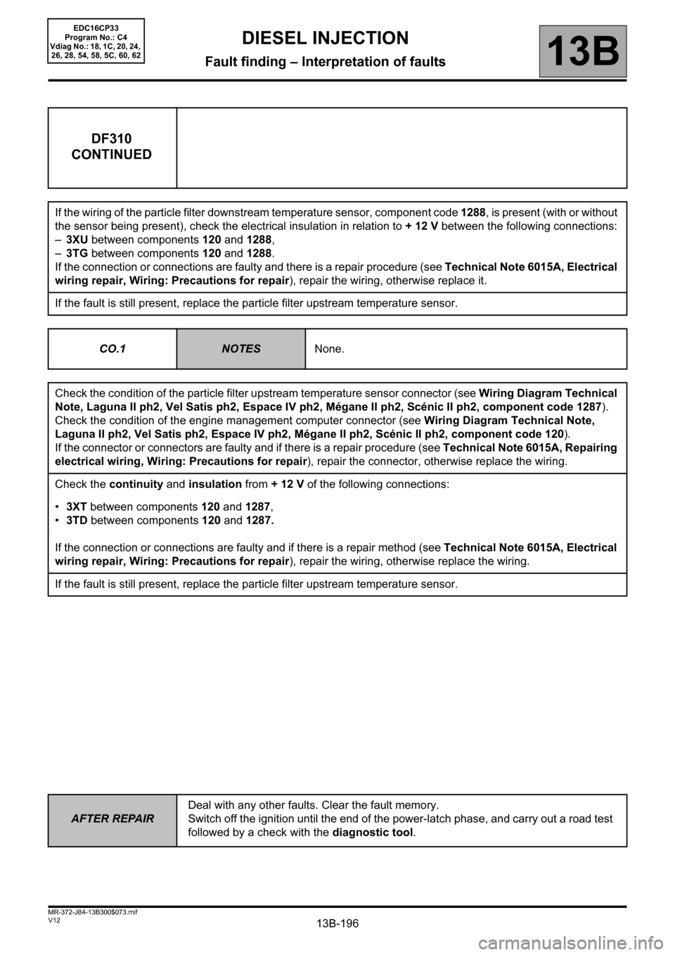
13B-196
AFTER REPAIRDeal with any other faults. Clear the fault memory.
Switch off the ignition until the end of the power-latch phase, and carry out a road test
followed by a check with the diagnostic tool.
V12 MR-372-J84-13B300$073.mif
DIESEL INJECTION
Fault finding – Interpretation of faults13B
DF310
CONTINUED
If the wiring of the particle filter downstream temperature sensor, component code 1288, is present (with or without
the sensor being present), check the electrical insulation in relation to + 12 V between the following connections:
–3XU between components 120 and 1288,
–3TG between components 120 and 1288.
If the connection or connections are faulty and there is a repair procedure (see Technical Note 6015A, Electrical
wiring repair, Wiring: Precautions for repair), repair the wiring, otherwise replace it.
If the fault is still present, replace the particle filter upstream temperature sensor.
CO.1
NOTESNone.
Check the condition of the particle filter upstream temperature sensor connector (see Wiring Diagram Technical
Note, Laguna II ph2, Vel Satis ph2, Espace IV ph2, Mégane II ph2, Scénic II ph2, component code 1287).
Check the condition of the engine management computer connector (see Wiring Diagram Technical Note,
Laguna II ph2, Vel Satis ph2, Espace IV ph2, Mégane II ph2, Scénic II ph2, component code 120).
If the connector or connectors are faulty and if there is a repair procedure (see Technical Note 6015A, Repairing
electrical wiring, Wiring: Precautions for repair), repair the connector, otherwise replace the wiring.
Check the continuity and insulation from + 12 V of the following connections:
•3XT between components 120 and 1287,
•3TD between components 120 and 1287.
If the connection or connections are faulty and if there is a repair method (see Technical Note 6015A, Electrical
wiring repair, Wiring: Precautions for repair), repair the wiring, otherwise replace the wiring.
If the fault is still present, replace the particle filter upstream temperature sensor.
EDC16CP33
Program No.: C4
Vdiag No.: 18, 1C, 20, 24,
26, 28, 54, 58, 5C, 60, 62
Page 197 of 510
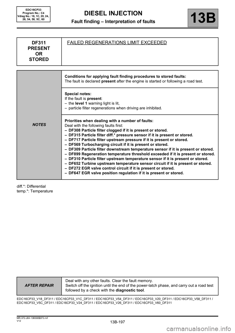
13B-197
AFTER REPAIRDeal with any other faults. Clear the fault memory.
Switch off the ignition until the end of the power-latch phase, and carry out a road test
followed by a check with the diagnostic tool.
V12 MR-372-J84-13B300$073.mif
DIESEL INJECTION
Fault finding – Interpretation of faults13B
diff.*: Differential
temp.*: Temperature
DF311
PRESENT
OR
STOREDFAILED REGENERATIONS LIMIT EXCEEDED
NOTESConditions for applying fault finding procedures to stored faults:
The fault is declared present after the engine is started or following a road test.
Special notes:
If the fault is present:
–the level 1 warning light is lit,
– particle filter regenerations when driving are inhibited.
Priorities when dealing with a number of faults:
Deal with the following faults first:
– DF308 Particle filter clogged if it is present or stored.
– DF315 Particle filter diff.* pressure sensor if it is present or stored.
– DF717 Particle filter upstream pressure if it is present or stored.
– DF569 Turbocharging circuit if it is present or stored.
– DF309 Particle filter downstream temperature sensor if it is present or stored.
– DF899 Regeneration temperature threshold exceeded if it is present or stored.
– DF310 Particle filter upstream temperature sensor if it is present or stored.
– DF652 Turbine upstream temperature sensor circuit if it is present or stored.
– DF272 EGR valve control circuit if it is present or stored.
– DF647 EGR valve position regulation if it is present or stored.
EDC16CP33_V18_DF311 / EDC16CP33_V1C_DF311 / EDC16CP33_V54_DF311 / EDC16CP33_V20_DF311 / EDC16CP33_V58_DF311 /
EDC16CP33_V5C_DF311 / EDC16CP33_V24_DF311 / EDC16CP33_V26_DF311 / EDC16CP33_V60_DF311
EDC16CP33
Program No.: C4
Vdiag No.: 18, 1C, 20, 24,
26, 54, 58, 5C, 60
Page 206 of 510
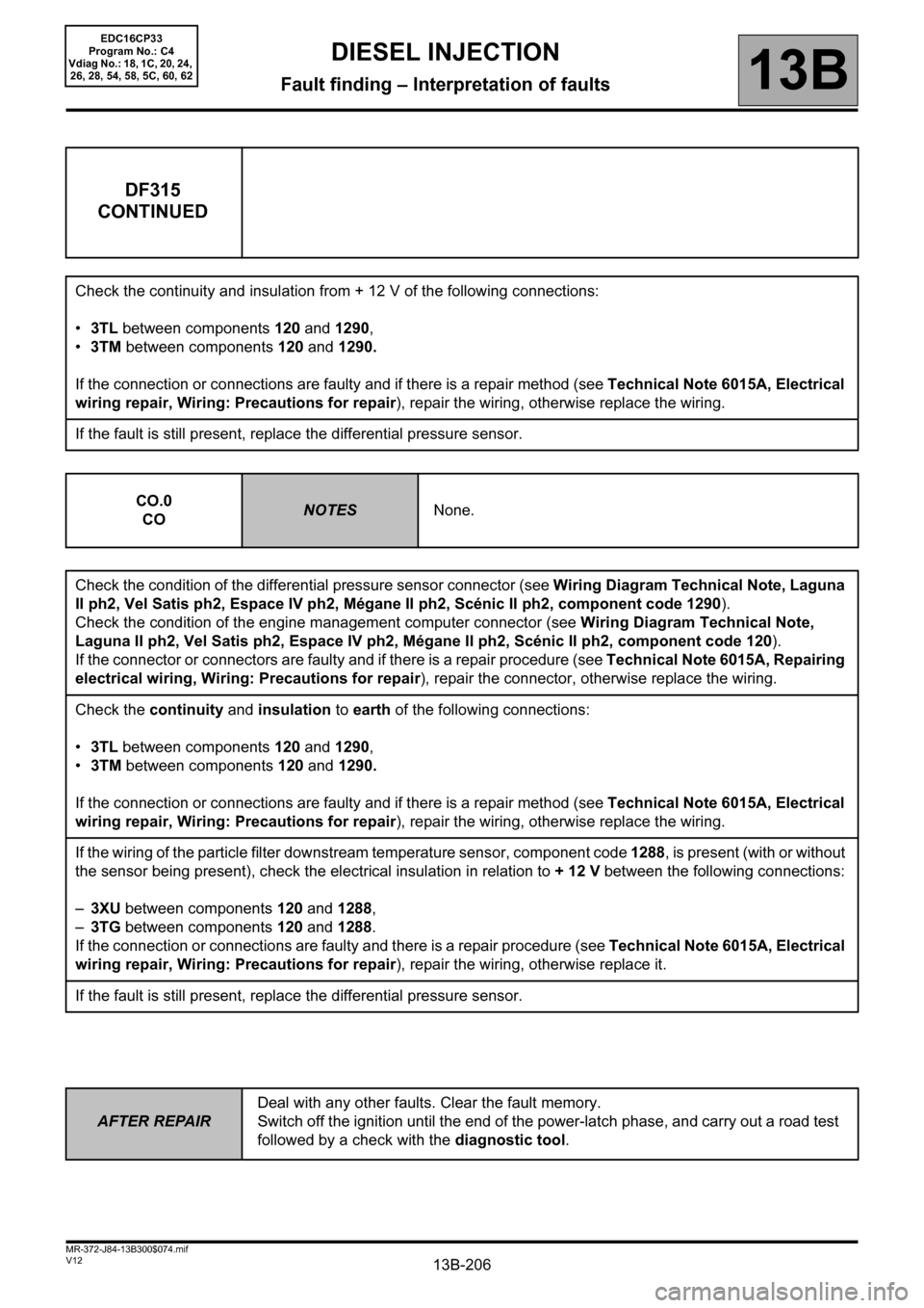
13B-206
AFTER REPAIRDeal with any other faults. Clear the fault memory.
Switch off the ignition until the end of the power-latch phase, and carry out a road test
followed by a check with the diagnostic tool.
V12 MR-372-J84-13B300$074.mif
DIESEL INJECTION
Fault finding – Interpretation of faults13B
DF315
CONTINUED
Check the continuity and insulation from + 12 V of the following connections:
•3TL between components 120 and 1290,
•3TM between components 120 and 1290.
If the connection or connections are faulty and if there is a repair method (see Technical Note 6015A, Electrical
wiring repair, Wiring: Precautions for repair), repair the wiring, otherwise replace the wiring.
If the fault is still present, replace the differential pressure sensor.
CO.0
CO
NOTESNone.
Check the condition of the differential pressure sensor connector (see Wiring Diagram Technical Note, Laguna
II ph2, Vel Satis ph2, Espace IV ph2, Mégane II ph2, Scénic II ph2, component code 1290).
Check the condition of the engine management computer connector (see Wiring Diagram Technical Note,
Laguna II ph2, Vel Satis ph2, Espace IV ph2, Mégane II ph2, Scénic II ph2, component code 120).
If the connector or connectors are faulty and if there is a repair procedure (see Technical Note 6015A, Repairing
electrical wiring, Wiring: Precautions for repair), repair the connector, otherwise replace the wiring.
Check the continuity and insulation to earth of the following connections:
•3TL between components 120 and 1290,
•3TM between components 120 and 1290.
If the connection or connections are faulty and if there is a repair method (see Technical Note 6015A, Electrical
wiring repair, Wiring: Precautions for repair), repair the wiring, otherwise replace the wiring.
If the wiring of the particle filter downstream temperature sensor, component code 1288, is present (with or without
the sensor being present), check the electrical insulation in relation to + 12 V between the following connections:
–3XU between components 120 and 1288,
–3TG between components 120 and 1288.
If the connection or connections are faulty and there is a repair procedure (see Technical Note 6015A, Electrical
wiring repair, Wiring: Precautions for repair), repair the wiring, otherwise replace it.
If the fault is still present, replace the differential pressure sensor.
EDC16CP33
Program No.: C4
Vdiag No.: 18, 1C, 20, 24,
26, 28, 54, 58, 5C, 60, 62
Page 213 of 510
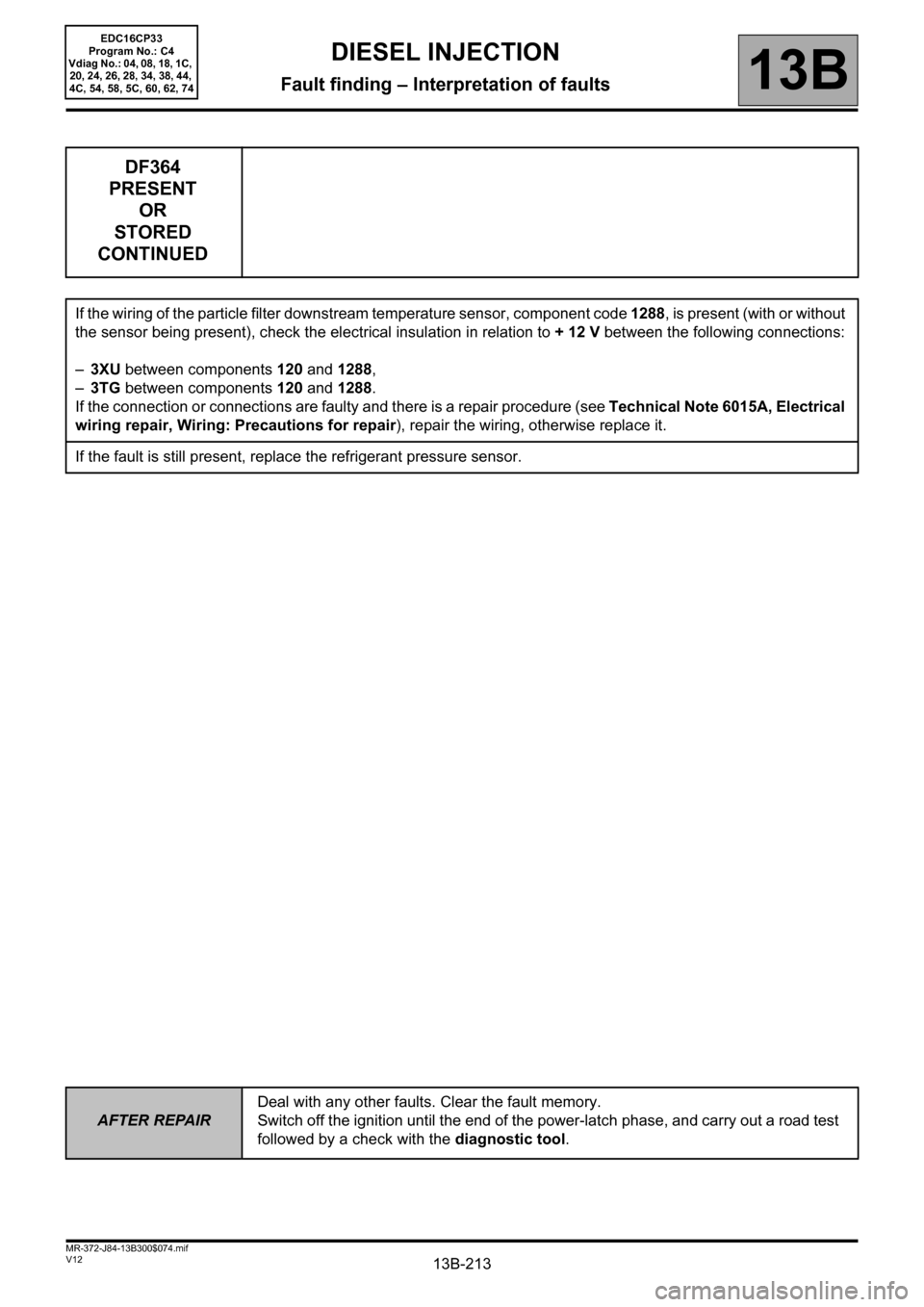
13B-213
AFTER REPAIRDeal with any other faults. Clear the fault memory.
Switch off the ignition until the end of the power-latch phase, and carry out a road test
followed by a check with the diagnostic tool.
V12 MR-372-J84-13B300$074.mif
DIESEL INJECTION
Fault finding – Interpretation of faults13B
DF364
PRESENT
OR
STORED
CONTINUED
If the wiring of the particle filter downstream temperature sensor, component code 1288, is present (with or without
the sensor being present), check the electrical insulation in relation to + 12 V between the following connections:
–3XU between components 120 and 1288,
–3TG between components 120 and 1288.
If the connection or connections are faulty and there is a repair procedure (see Technical Note 6015A, Electrical
wiring repair, Wiring: Precautions for repair), repair the wiring, otherwise replace it.
If the fault is still present, replace the refrigerant pressure sensor.
EDC16CP33
Program No.: C4
Vdiag No.: 04, 08, 18, 1C,
20, 24, 26, 28, 34, 38, 44,
4C, 54, 58, 5C, 60, 62, 74
Page 230 of 510
13B-230
AFTER REPAIRDeal with any other faults. Clear the fault memory.
Switch off the ignition until the end of the power-latch phase, and carry out a road test
followed by a check with the diagnostic tool.
V12 MR-372-J84-13B300$074.mif
DIESEL INJECTION
Fault finding – Interpretation of faults13B
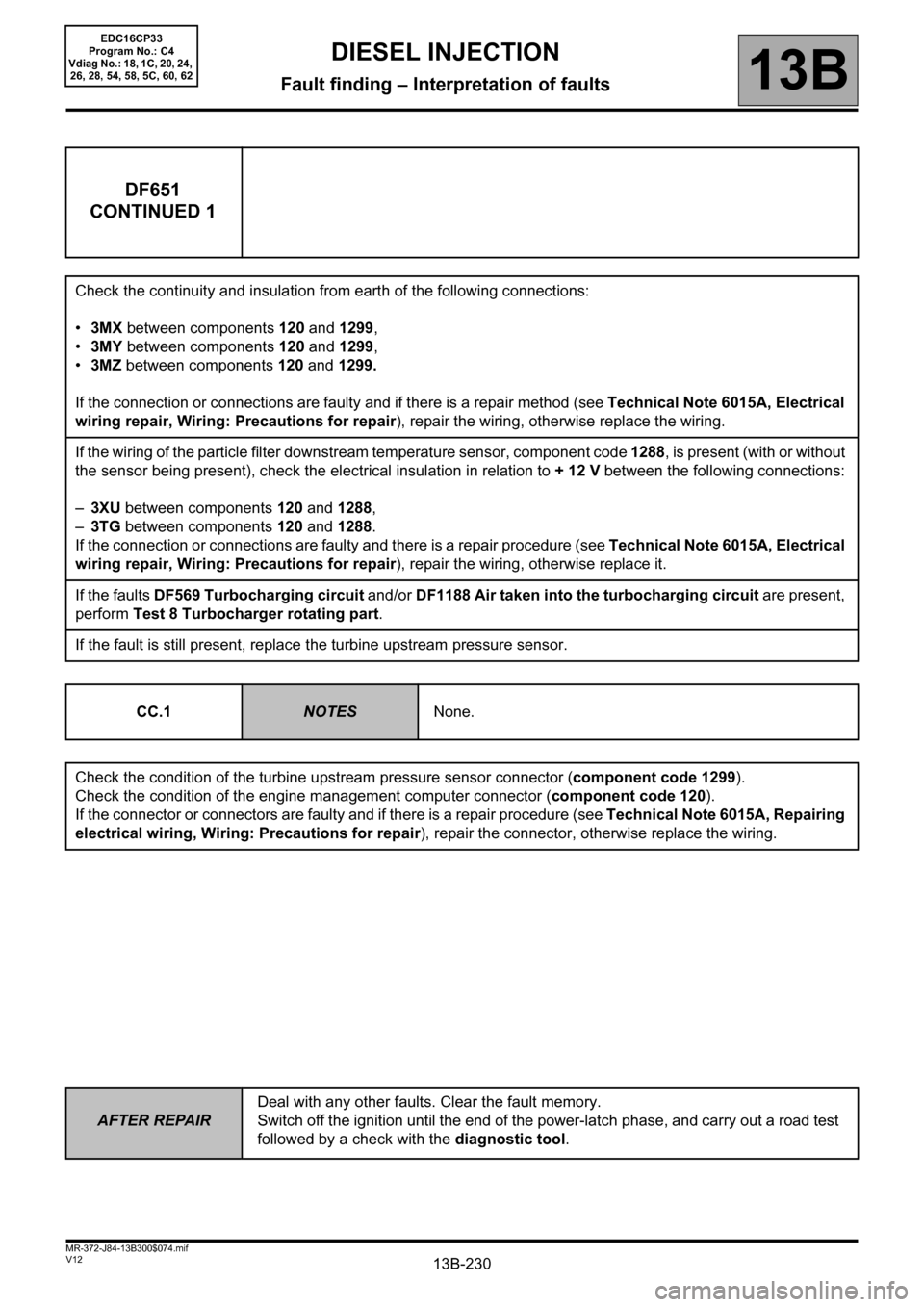
DF651
CONTINUED 1
Check the continuity and insulation from earth of the following connections:
•3MX between components 120 and 1299,
•3MY between components 120 and 1299,
•3MZ between components 120 and 1299.
If the connection or connections are faulty and if there is a repair method (see Technical Note 6015A, Electrical
wiring repair, Wiring: Precautions for repair), repair the wiring, otherwise replace the wiring.
If the wiring of the particle filter downstream temperature sensor, component code 1288, is present (with or without
the sensor being present), check the electrical insulation in relation to + 12 V between the following connections:
–3XU between components 120 and 1288,
–3TG between components 120 and 1288.
If the connection or connections are faulty and there is a repair procedure (see Technical Note 6015A, Electrical
wiring repair, Wiring: Precautions for repair), repair the wiring, otherwise replace it.
If the faults DF569 Turbocharging circuit and/or DF1188 Air taken into the turbocharging circuit are present,
perform Test 8 Turbocharger rotating part.
If the fault is still present, replace the turbine upstream pressure sensor.
CC.1
NOTESNone.
Check the condition of the turbine upstream pressure sensor connector (component code 1299).
Check the condition of the engine management computer connector (component code 120).
If the connector or connectors are faulty and if there is a repair procedure (see Technical Note 6015A, Repairing
electrical wiring, Wiring: Precautions for repair), repair the connector, otherwise replace the wiring.
EDC16CP33
Program No.: C4
Vdiag No.: 18, 1C, 20, 24,
26, 28, 54, 58, 5C, 60, 62
Page 326 of 510
13B-326V12 MR-372-J84-13B300$110.mif
DIESEL INJECTION
Fault finding – Parameter summary table13B
EDC16CP33
Program No.: C4
VDiag No.: 04, 08, 18, 1C,
20, 24, 26, 28, 34, 38, 44,
4C, 54, 58, 5C, 60, 62, 74
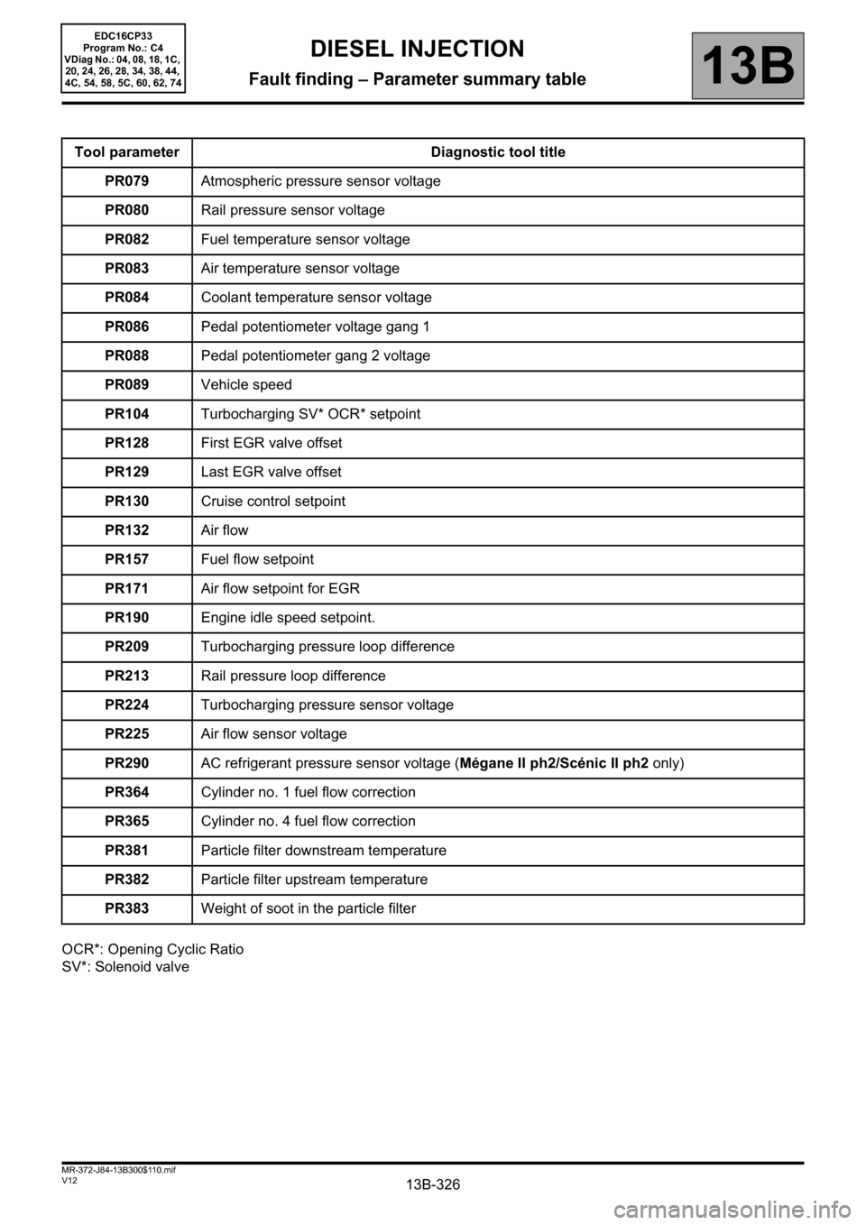
OCR*: Opening Cyclic Ratio
SV*: Solenoid valveTool parameter Diagnostic tool title
PR079Atmospheric pressure sensor voltage
PR080Rail pressure sensor voltage
PR082Fuel temperature sensor voltage
PR083Air temperature sensor voltage
PR084Coolant temperature sensor voltage
PR086Pedal potentiometer voltage gang 1
PR088Pedal potentiometer gang 2 voltage
PR089Vehicle speed
PR104Turbocharging SV* OCR* setpoint
PR128First EGR valve offset
PR129Last EGR valve offset
PR130Cruise control setpoint
PR132Air flow
PR157Fuel flow setpoint
PR171Air flow setpoint for EGR
PR190Engine idle speed setpoint.
PR209Turbocharging pressure loop difference
PR213Rail pressure loop difference
PR224Turbocharging pressure sensor voltage
PR225Air flow sensor voltage
PR290AC refrigerant pressure sensor voltage (Mégane II ph2/Scénic II ph2 only)
PR364Cylinder no. 1 fuel flow correction
PR365Cylinder no. 4 fuel flow correction
PR381Particle filter downstream temperature
PR382Particle filter upstream temperature
PR383Weight of soot in the particle filter
Page 386 of 510
13B-386V12 MR-372-J84-13B300$122.mif
DIESEL INJECTION
Fault finding – Interpretation of parameters13B
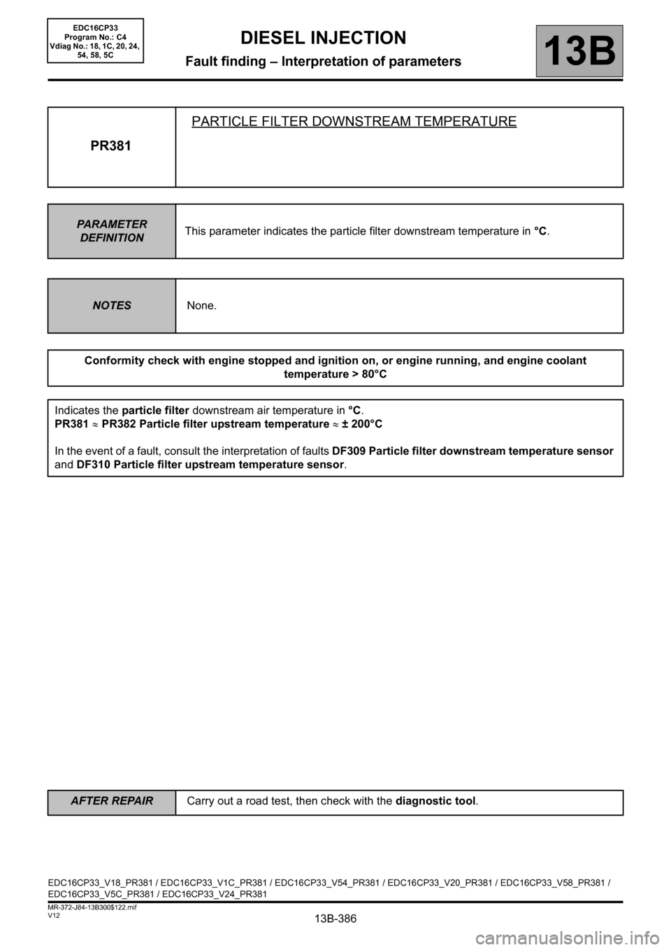
PR381PARTICLE FILTER DOWNSTREAM TEMPERATURE
PARAMETER
DEFINITIONThis parameter indicates the particle filter downstream temperature in °C.
NOTESNone.
Conformity check with engine stopped and ignition on, or engine running, and engine coolant
temperature > 80°C
Indicates the particle filter downstream air temperature in °C.
PR381 ≈ PR382 Particle filter upstream temperature ≈ ± 200°C
In the event of a fault, consult the interpretation of faults DF309 Particle filter downstream temperature sensor
and DF310 Particle filter upstream temperature sensor.
EDC16CP33_V18_PR381 / EDC16CP33_V1C_PR381 / EDC16CP33_V54_PR381 / EDC16CP33_V20_PR381 / EDC16CP33_V58_PR381 /
EDC16CP33_V5C_PR381 / EDC16CP33_V24_PR381
EDC16CP33
Program No.: C4
Vdiag No.: 18, 1C, 20, 24,
54, 58, 5C
AFTER REPAIRCarry out a road test, then check with the diagnostic tool.
Page 387 of 510

13B-387V12 MR-372-J84-13B300$122.mif
DIESEL INJECTION
Fault finding – Interpretation of parameters13B
PR382PARTICLE FILTER UPSTREAM TEMPERATURE
PARAMETER
DEFINITIONThis parameter indicates the air temperature of the exhaust gas upstream of the particle
filter in °C.
NOTESNone.
Conformity check with engine stopped and ignition on, or engine running, and engine coolant
temperature > 80°C
The value of the air temperature of the exhaust gas upstream of the particle filter must be:
PR382 ≈ 200°C
In the event of a fault, consult the interpretation of faults DF309 Particle filter downstream temperature sensor
and DF310 Particle filter upstream temperature sensor.
EDC16CP33_V18_PR382 / EDC16CP33_V1C_PR382 / EDC16CP33_V54_PR382 / EDC16CP33_V20_PR382 / EDC16CP33_V58_PR382 /
EDC16CP33_V5C_PR382 / EDC16CP33_V24_PR382 / EDC16CP33_V28_PR382 / EDC16CP33_V62_PR382 / EDC16CP33_V26_PR382 /
EDC16CP33_V60_PR382
EDC16CP33
Program No.: C4
Vdiag No.: 18, 1C, 20, 24,
26, 28, 54, 58, 5C, 60, 62
AFTER REPAIRCarry out a road test, then check with the diagnostic tool.
Page 428 of 510
13B-428V12 MR-372-J84-13B300$150.mif
DIESEL INJECTION
Fault finding – Interpretation of commands13B
SC017
CONTINUED 1
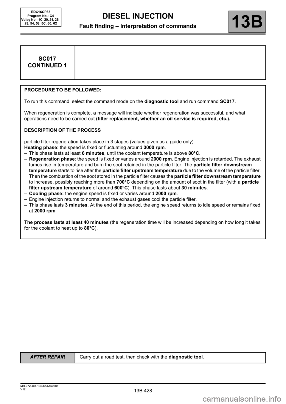
PROCEDURE TO BE FOLLOWED:
To run this command, select the command mode on the diagnostic tool and run command SC017.
When regeneration is complete, a message will indicate whether regeneration was successful, and what
operations need to be carried out (filter replacement, whether an oil service is required, etc.).
DESCRIPTION OF THE PROCESS
particle filter regeneration takes place in 3 stages (values given as a guide only):
Heating phase: the speed is fixed or fluctuating around 3000 rpm.
– This phase lasts at least 6minutes, until the coolant temperature is above 80°C.
–Regeneration phase: the speed is fixed or varies around 2000 rpm. Engine injection is retarded. The exhaust
fumes rise in temperature and burn the soot retained in the particle filter. The particle filter downstream
temperature starts to rise after the particle filter upstream temperature due to the volume of the particle filter.
Then the combustion of the soot stored in the particle filter causes the particle filter downstream temperature
to increase, possibly reaching more than 700°C depending on the amount of soot in the filter (with a particle
filter upstream temperature of around 600°C). This phase lasts about 30 minutes.
–Cooling phase: the engine speed is fixed or varies around 2000 rpm.
– Engine injection returns to normal and the exhaust gases cool the particle filter.
– This phase lasts 3 minutes. At the end of this period, the engine speed returns to idle speed or remains fixed
at 2000 rpm.
The process lasts at least 40 minutes (the regeneration time will be increased depending on how long it takes
for the coolant to heat up to 80°C).
EDC16CP33
Program No.: C4
Vdiag No.: 1C, 20, 24, 26,
28, 54, 58, 5C, 60, 62
AFTER REPAIRCarry out a road test, then check with the diagnostic tool.
Page 502 of 510
13B-502V12 MR-372-J84-13B300$180.mif
DIESEL INJECTION
Fault finding – Test13B
TEST6 Fuel return rail valve check
This test consists of creating a vacuum downstream of the anti-return valve of the injector return rail and checking
whether fuel is drawn in by the valve.
Fitting:
Remove the rail protector.
Disconnect the union of the return rail on injector 4 (on the gearbox side).
Disconnect the union downstream of the anti-return valve.
Connect the 8 mm quick-release coupling.
Connect a transparent hose (resistant to diesel, length 60 cm and internal diameter 8 mm).
Connect a manual vacuum pump.
Gradually apply a vacuum up to 0.5 bar.
If more than a cm of diesel is quickly drawn into the hose, the valve is leaking. Stop the vacuum immediately.
Replace the diesel injector fuel return rail and its overpressure valve (see MR364 (Mégane II ph2), MR370 (Scénic
II ph2), MR 395 (Laguna II ph2), MR 402 (Vel-Satis ph2), MR405 (Espace IV ph2) Mechanical, 13B, Diesel
injection, Diesel injector fuel return rail: Removal - Refitting).
Otherwise, maintain the vacuum for 1 minute.
If less than a cm of diesel is drawn into the hose, the valve of the rail is not leaking.
End of test.
EDC16CP33
Program No.: C4
Vdiag No.: 04, 08, 18, 1C,
20, 24, 26, 28, 34, 38, 44,
4C, 54, 58, 5C, 60, 62, 74
EDC16CP33_V18_TEST6 / EDC16CP33_V1C_TEST6 / EDC16CP33_V54_TEST6 / EDC16CP33_V20_TEST6 / EDC16CP33_V58_TEST6 /
EDC16CP33_V5C_TEST6 / EDC16CP33_V24_TEST6 / EDC16CP33_V04_TEST6 / EDC16CP33_V08_TEST6 / EDC16CP33_V44_TEST6 /
EDC16CP33_V4C_TEST6 / EDC16CP33_V34_TEST6 / EDC16CP33_V38_TEST6 / EDC16CP33_V74_TEST6 / EDC16CP33_V28_TEST6 /
EDC16CP33_V62_TEST6 / EDC16CP33_V26_TEST6 / EDC16CP33_V60_TEST6