overheating RENAULT SCENIC 2012 J95 / 3.G Engine And Peripherals EDC16CP33 Workshop Manual
[x] Cancel search | Manufacturer: RENAULT, Model Year: 2012, Model line: SCENIC, Model: RENAULT SCENIC 2012 J95 / 3.GPages: 510, PDF Size: 2.98 MB
Page 19 of 510
13B-19V12 MR-372-J84-13B300$030.mif
DIESEL INJECTION
Fault finding – System operation13B
EDC16CP33
Program No.: C4
Vdiag No.: 04, 08, 18, 1C,
20, 24, 26, 28, 34, 38, 44,
4C, 54, 58, 5C, 60, 62, 74
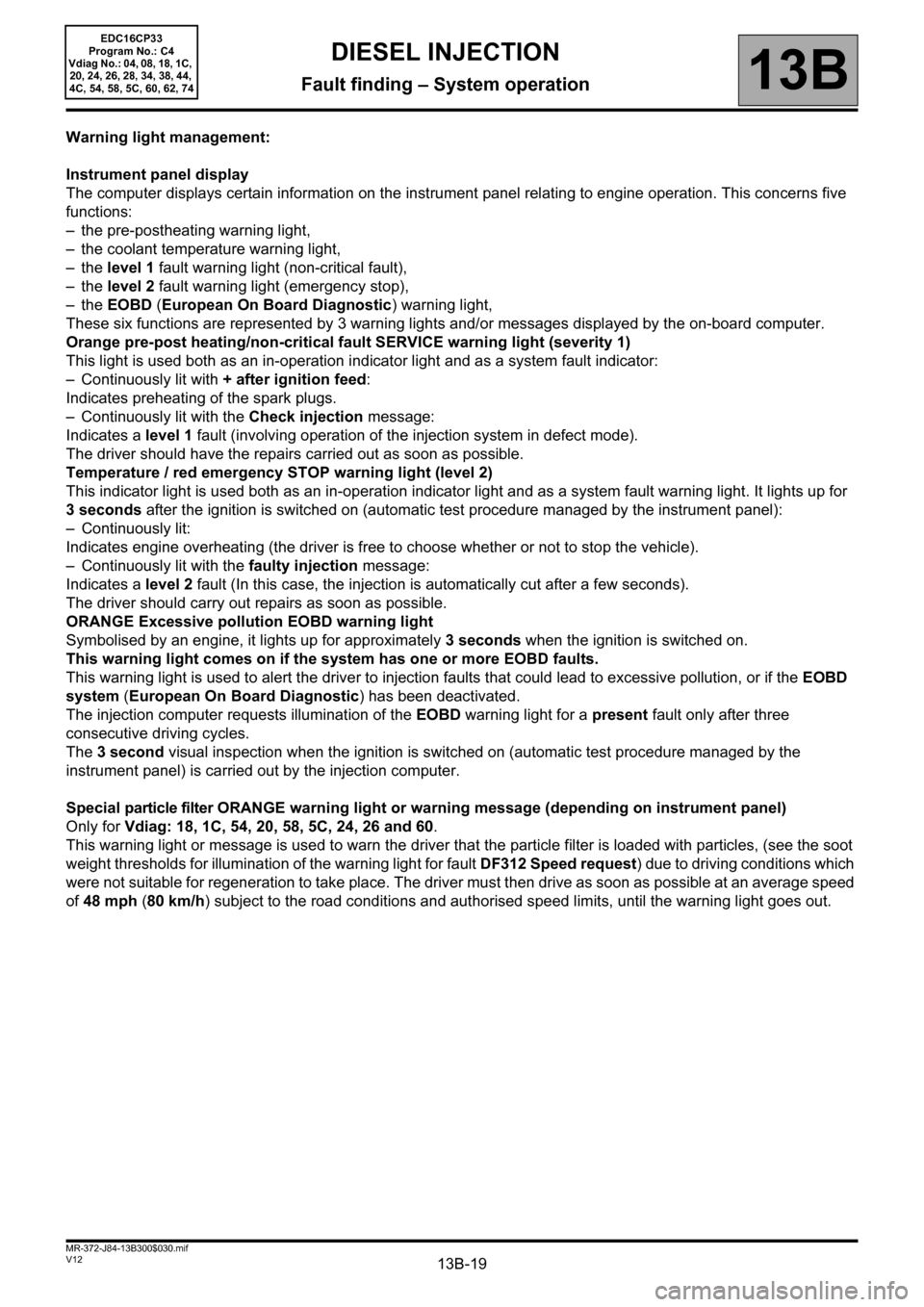
Warning light management:
Instrument panel display
The computer displays certain information on the instrument panel relating to engine operation. This concerns five
functions:
– the pre-postheating warning light,
– the coolant temperature warning light,
–the level 1 fault warning light (non-critical fault),
–the level 2 fault warning light (emergency stop),
–the EOBD (European On Board Diagnostic) warning light,
These six functions are represented by 3 warning lights and/or messages displayed by the on-board computer.
Orange pre-post heating/non-critical fault SERVICE warning light (severity 1)
This light is used both as an in-operation indicator light and as a system fault indicator:
– Continuously lit with + after ignition feed:
Indicates preheating of the spark plugs.
– Continuously lit with the Check injection message:
Indicates a level 1 fault (involving operation of the injection system in defect mode).
The driver should have the repairs carried out as soon as possible.
Temperature / red emergency STOP warning light (level 2)
This indicator light is used both as an in-operation indicator light and as a system fault warning light. It lights up for
3 seconds after the ignition is switched on (automatic test procedure managed by the instrument panel):
– Continuously lit:
Indicates engine overheating (the driver is free to choose whether or not to stop the vehicle).
– Continuously lit with the faulty injection message:
Indicates a level 2 fault (In this case, the injection is automatically cut after a few seconds).
The driver should carry out repairs as soon as possible.
ORANGE Excessive pollution EOBD warning light
Symbolised by an engine, it lights up for approximately 3 seconds when the ignition is switched on.
This warning light comes on if the system has one or more EOBD faults.
This warning light is used to alert the driver to injection faults that could lead to excessive pollution, or if the EOBD
system (European On Board Diagnostic) has been deactivated.
The injection computer requests illumination of the EOBD warning light for a present fault only after three
consecutive driving cycles.
The 3 second visual inspection when the ignition is switched on (automatic test procedure managed by the
instrument panel) is carried out by the injection computer.
Special particle filter ORANGE warning light or warning message (depending on instrument panel)
Only for Vdiag: 18, 1C, 54, 20, 58, 5C, 24, 26 and 60.
This warning light or message is used to warn the driver that the particle filter is loaded with particles, (see the soot
weight thresholds for illumination of the warning light for fault DF312 Speed request) due to driving conditions which
were not suitable for regeneration to take place. The driver must then drive as soon as possible at an average speed
of 48 mph (80 km/h) subject to the road conditions and authorised speed limits, until the warning light goes out.
Page 473 of 510
13B-473
AFTER REPAIRCarry out a road test, then check with the diagnostic tool.
V12 MR-372-J84-13B300$170.mif
DIESEL INJECTION
Fault finding – Fault Finding Chart13B
ALP2
CONTINUED 1
If the connection or connections are faulty and there is a repair procedure (see Technical Note 6015A, Electrical
wiring repair, Wiring: Precautions for repair), repair the wiring, otherwise replace it.
Check the conformity of the engine earths (oxidation, tightness, etc.).
Check the mounting and condition (overheating) of the sensor.
Check the synchronisation of the camshaft sensors and the engine speed sensors with the display of ET238
Synchronisation. If synchronisation is not active, refer to the checks described in DF195 Camshaft/engine
speed sensor consistency.
Test the high pressure fuel circuit:
Run scenario SC035 High pressure fuel circuit fault finding.
To interpret the result, apply the interpretation of command SC035 (see Interpretation of commands).
Check the fuel circuit sealing: run Test 3 Low pressure circuit check.
If Test 3 is correct.
If Test 3 is not correct, proceed as follows:
Check the conformity of the type of heater plugs configured:
For Vdiag 20, 24, 38 and 74: consult ET781 Heater plugs in the Ignition/Preheating subfunction and check the
conformity with the type of plugs installed:
– Slow plugs have a black ring.
– Fast plugs have a white ring.
If the heater plugs are being replaced with plugs of a different type (see Replacement of components, Replacing
heater plugs).
For all Vdiags, check that all 4 plugs have the same colour ring.
Check that the heater plugs are actuated using the AC037 Preheating relay command.
Check the sealing and condition of the inlet circuit: run Test 4 Turbocharged air inlet circuit check, and follow
the related fault finding procedure (see Test 4).
EDC16CP33
Program No.: C4
Vdiag No.: 04, 08, 18, 1C,
20, 24, 26, 28, 34, 38, 44,
4C, 54, 58, 5C, 60, 62, 74
Page 476 of 510
13B-476
AFTER REPAIRCarry out a road test, then check with the diagnostic tool.
V12 MR-372-J84-13B300$170.mif
DIESEL INJECTION
Fault finding – Fault Finding Chart13B
ALP4 Poor performance
NOTESBefore analysing this customer complaint, check that there are no faults, and the
conformity (or otherwise) of the parameters and statuses, using the diagnostic tool.
If the customer complaint is not eliminated, perform the following checks.
IMPORTANT:
In the event of the engine overheating above 118°C, the computer deliberately limits the fuel flow (overheating
warning light comes on from 115°C).
– Please observe the cleanliness guidelines and safety advice.
Note:
For the M9R 724 (Vdiag 5C and 58):
The engine is limited to 3000 rpm if the vehicle is stationary or if the vehicle speed is less than 4 mph (7 km/h)
and if the engine is warm.
EDC16CP33_V18_ALP04 / EDC16CP33_V1C_ALP04 / EDC16CP33_V54_ALP04 / EDC16CP33_V20_ALP04 / EDC16CP33_V58_ALP04 /
EDC16CP33_V5C_ALP04 / EDC16CP33_V24_ALP04 / EDC16CP33_V04_ALP04 / EDC16CP33_V08_ALP04 / EDC16CP33_V44_ALP04 /
EDC16CP33_V4C_ALP04 / EDC16CP33_V34_ALP04 / EDC16CP33_V38_ALP04 / EDC16CP33_V74_ALP04 / EDC16CP33_V28_ALP04 /
EDC16CP33_V62_ALP04 / EDC16CP33_V26_ALP04 / EDC16CP33_V60_ALP04
EDC16CP33
Program No.: C4
Vdiag No.: 04, 08, 18, 1C,
20, 24, 26, 28, 34, 38, 44,
4C, 54, 58, 5C, 60, 62, 74
Page 480 of 510
13B-480
AFTER REPAIRCarry out a road test, then check with the diagnostic tool.
V12 MR-372-J84-13B300$170.mif
DIESEL INJECTION
Fault finding – Fault Finding Chart13B
ALP5 Irregular engine operation
NOTESBefore analysing this customer complaint, check that there are no faults, and the
conformity (or otherwise) of the parameters and statuses, using the diagnostic tool.
If the customer complaint is not eliminated, perform the following checks.
Use the Wiring Diagram Technical Note, Laguna II ph2, Vel Satis ph2, Espace IV
ph2, Mégane II ph2, Scénic II ph2.
If the engine races during gear changes, if there is a floor mat, check that this is not blocking the accelerator pedal,
the brake pedal and the clutch pedal, then check the conformity of the clutch switch and the conformity of the
accelerator pedal sensor when the pedal is released (see PR086 Pedal potentiometer voltage gang 1 and
PR088 Pedal potentiometer voltage gang 2, Sensor supply).
Measure the resistance between connections 3BG and 3BL of component 149.
If the sensor resistance is not between:
741 Ω < X < 905 Ω at +20°C, replace the sensor.
Check the continuity and absence of interference resistance on the following connections:
•3BG between the components 120 and 149,
•3BL between components 120 and 149.
If the connection or connections are faulty and there is a repair procedure (see Technical Note 6015A, Electrical
wiring repair, Wiring: Precautions for repair), repair the wiring, otherwise replace it.
Check the conformity of the engine earths (oxidation, tightness, etc.).
Check the mounting and condition (overheating) of the sensor.
Check the low pressure circuit: run Test 3 Low pressure circuit check.
Apply the air flow checking procedure, (see conformity in the interpretation of statuses and parameters).
Check the turbocharger: apply Test 7 Variable geometry turbocharger control.
If the fault is still present, test the high pressure fuel circuit:
Run scenario SC035 High pressure fuel circuit fault finding.
To interpret the result, apply the interpretation of command SC035 (see Interpretation of commands).
EDC16CP33_V18_ALP05 / EDC16CP33_V1C_ALP05 / EDC16CP33_V54_ALP05 / EDC16CP33_V20_ALP05 / EDC16CP33_V58_ALP05 /
EDC16CP33_V5C_ALP05 / EDC16CP33_V24_ALP05 / EDC16CP33_V04_ALP05 / EDC16CP33_V08_ALP05 / EDC16CP33_V44_ALP05 /
EDC16CP33_V4C_ALP05 / EDC16CP33_V34_ALP05 / EDC16CP33_V38_ALP05 / EDC16CP33_V74_ALP05 / EDC16CP33_V28_ALP05 /
EDC16CP33_V62_ALP05 / EDC16CP33_V26_ALP05 / EDC16CP33_V60_ALP05
EDC16CP33
Program No.: C4
Vdiag No.: 04, 08, 18, 1C,
20, 24, 26, 28, 34, 38, 44,
4C, 54, 58, 5C, 60, 62, 74
Page 506 of 510
13B-506V12 MR-372-J84-13B300$180.mif
DIESEL INJECTION
Fault finding – Test13B
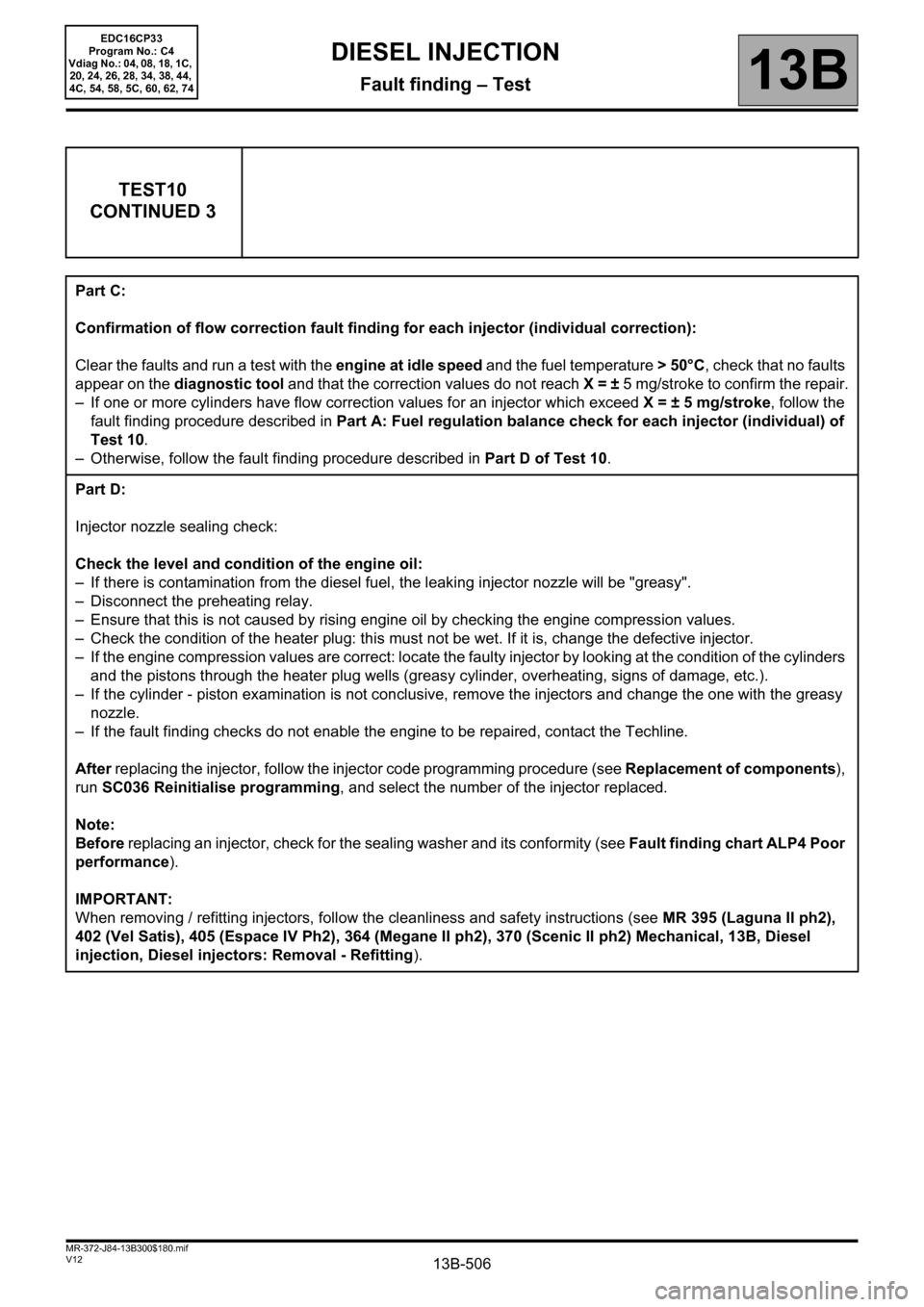
TEST10
CONTINUED 3
Part C:
Confirmation of flow correction fault finding for each injector (individual correction):
Clear the faults and run a test with the engine at idle speed and the fuel temperature > 50°C, check that no faults
appear on the diagnostic tool and that the correction values do not reach X = ± 5 mg/stroke to confirm the repair.
– If one or more cylinders have flow correction values for an injector which exceed X = ± 5 mg/stroke, follow the
fault finding procedure described in Part A: Fuel regulation balance check for each injector (individual) of
Test 10.
– Otherwise, follow the fault finding procedure described in Part D of Test 10.
Part D:
Injector nozzle sealing check:
Check the level and condition of the engine oil:
– If there is contamination from the diesel fuel, the leaking injector nozzle will be "greasy".
– Disconnect the preheating relay.
– Ensure that this is not caused by rising engine oil by checking the engine compression values.
– Check the condition of the heater plug: this must not be wet. If it is, change the defective injector.
– If the engine compression values are correct: locate the faulty injector by looking at the condition of the cylinders
and the pistons through the heater plug wells (greasy cylinder, overheating, signs of damage, etc.).
– If the cylinder - piston examination is not conclusive, remove the injectors and change the one with the greasy
nozzle.
– If the fault finding checks do not enable the engine to be repaired, contact the Techline.
After replacing the injector, follow the injector code programming procedure (see Replacement of components),
run SC036 Reinitialise programming, and select the number of the injector replaced.
Note:
Before replacing an injector, check for the sealing washer and its conformity (see Fault finding chart ALP4 Poor
performance).
IMPORTANT:
When removing / refitting injectors, follow the cleanliness and safety instructions (see MR 395 (Laguna II ph2),
402 (Vel Satis), 405 (Espace IV Ph2), 364 (Megane II ph2), 370 (Scenic II ph2) Mechanical, 13B, Diesel
injection, Diesel injectors: Removal - Refitting).
EDC16CP33
Program No.: C4
Vdiag No.: 04, 08, 18, 1C,
20, 24, 26, 28, 34, 38, 44,
4C, 54, 58, 5C, 60, 62, 74