rail pressure RENAULT SCENIC 2012 J95 / 3.G Engine And Peripherals EDC16CP33 Workshop Manual
[x] Cancel search | Manufacturer: RENAULT, Model Year: 2012, Model line: SCENIC, Model: RENAULT SCENIC 2012 J95 / 3.GPages: 510, PDF Size: 2.98 MB
Page 11 of 510
13B-11V12 MR-372-J84-13B300$030.mif
13B
EDC16CP33
Program No.: C4
Vdiag No.: 04, 08, 18, 1C,
20, 24, 26, 28, 34, 38, 44,
4C, 54, 58, 5C, 60, 62, 74
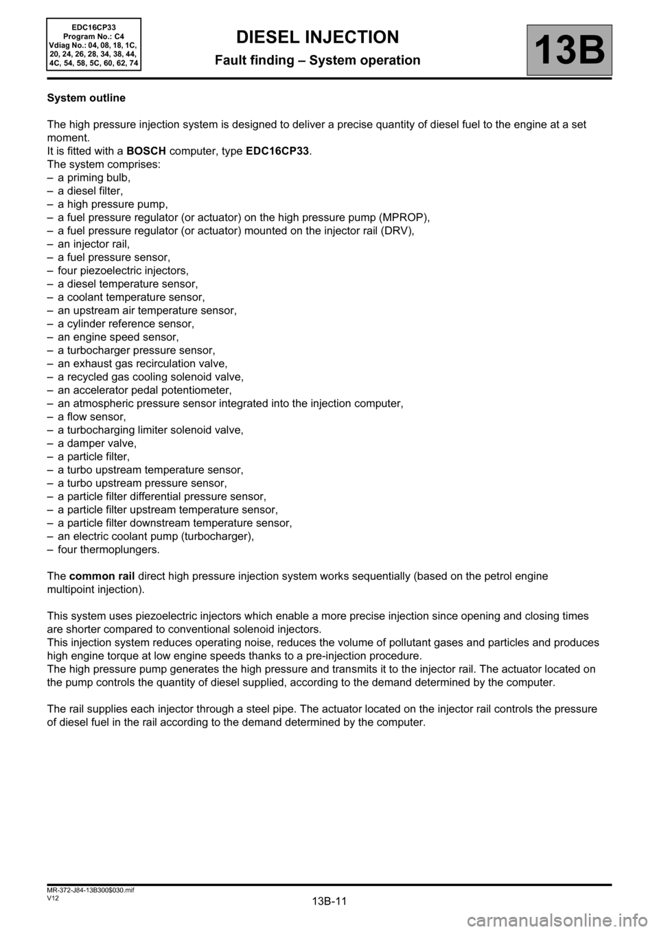
System outline
The high pressure injection system is designed to deliver a precise quantity of diesel fuel to the engine at a set
moment.
It is fitted with a BOSCH computer, type EDC16CP33.
The system comprises:
– a priming bulb,
– a diesel filter,
– a high pressure pump,
– a fuel pressure regulator (or actuator) on the high pressure pump (MPROP),
– a fuel pressure regulator (or actuator) mounted on the injector rail (DRV),
– an injector rail,
– a fuel pressure sensor,
– four piezoelectric injectors,
– a diesel temperature sensor,
– a coolant temperature sensor,
– an upstream air temperature sensor,
– a cylinder reference sensor,
– an engine speed sensor,
– a turbocharger pressure sensor,
– an exhaust gas recirculation valve,
– a recycled gas cooling solenoid valve,
– an accelerator pedal potentiometer,
– an atmospheric pressure sensor integrated into the injection computer,
– a flow sensor,
– a turbocharging limiter solenoid valve,
– a damper valve,
– a particle filter,
– a turbo upstream temperature sensor,
– a turbo upstream pressure sensor,
– a particle filter differential pressure sensor,
– a particle filter upstream temperature sensor,
– a particle filter downstream temperature sensor,
– an electric coolant pump (turbocharger),
– four thermoplungers.
The common rail direct high pressure injection system works sequentially (based on the petrol engine
multipoint injection).
This system uses piezoelectric injectors which enable a more precise injection since opening and closing times
are shorter compared to conventional solenoid injectors.
This injection system reduces operating noise, reduces the volume of pollutant gases and particles and produces
high engine torque at low engine speeds thanks to a pre-injection procedure.
The high pressure pump generates the high pressure and transmits it to the injector rail. The actuator located on
the pump controls the quantity of diesel supplied, according to the demand determined by the computer.
The rail supplies each injector through a steel pipe. The actuator located on the injector rail controls the pressure
of diesel fuel in the rail according to the demand determined by the computer.
DIESEL INJECTION
Fault finding – System operation
Page 12 of 510
13B-12V12 MR-372-J84-13B300$030.mif
DIESEL INJECTION
Fault finding – System operation13B
EDC16CP33
Program No.: C4
Vdiag No.: 04, 08, 18, 1C,
20, 24, 26, 28, 34, 38, 44,
4C, 54, 58, 5C, 60, 62, 74
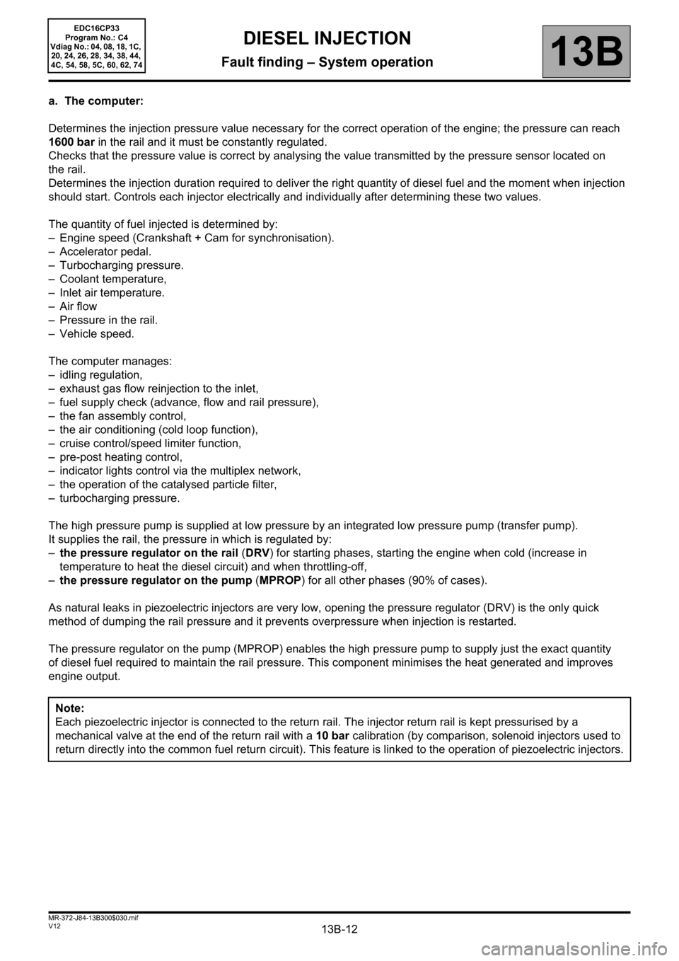
a. The computer:
Determines the injection pressure value necessary for the correct operation of the engine; the pressure can reach
1600 bar in the rail and it must be constantly regulated.
Checks that the pressure value is correct by analysing the value transmitted by the pressure sensor located on
the rail.
Determines the injection duration required to deliver the right quantity of diesel fuel and the moment when injection
should start. Controls each injector electrically and individually after determining these two values.
The quantity of fuel injected is determined by:
– Engine speed (Crankshaft + Cam for synchronisation).
– Accelerator pedal.
– Turbocharging pressure.
– Coolant temperature,
– Inlet air temperature.
–Air flow
– Pressure in the rail.
– Vehicle speed.
The computer manages:
– idling regulation,
– exhaust gas flow reinjection to the inlet,
– fuel supply check (advance, flow and rail pressure),
– the fan assembly control,
– the air conditioning (cold loop function),
– cruise control/speed limiter function,
– pre-post heating control,
– indicator lights control via the multiplex network,
– the operation of the catalysed particle filter,
– turbocharging pressure.
The high pressure pump is supplied at low pressure by an integrated low pressure pump (transfer pump).
It supplies the rail, the pressure in which is regulated by:
–the pressure regulator on the rail (DRV) for starting phases, starting the engine when cold (increase in
temperature to heat the diesel circuit) and when throttling-off,
–the pressure regulator on the pump (MPROP) for all other phases (90% of cases).
As natural leaks in piezoelectric injectors are very low, opening the pressure regulator (DRV) is the only quick
method of dumping the rail pressure and it prevents overpressure when injection is restarted.
The pressure regulator on the pump (MPROP) enables the high pressure pump to supply just the exact quantity
of diesel fuel required to maintain the rail pressure. This component minimises the heat generated and improves
engine output.
Note:
Each piezoelectric injector is connected to the return rail. The injector return rail is kept pressurised by a
mechanical valve at the end of the return rail with a 10 bar calibration (by comparison, solenoid injectors used to
return directly into the common fuel return circuit). This feature is linked to the operation of piezoelectric injectors.
Page 13 of 510
13B-13V12 MR-372-J84-13B300$030.mif
DIESEL INJECTION
Fault finding – System operation13B
EDC16CP33
Program No.: C4
Vdiag No.: 04, 08, 18, 1C,
20, 24, 26, 28, 34, 38, 44,
4C, 54, 58, 5C, 60, 62, 74
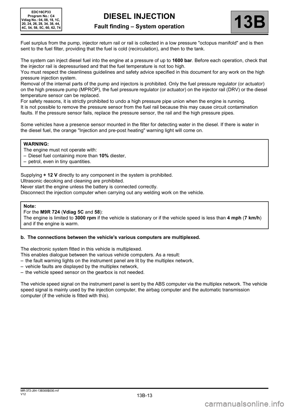
Fuel surplus from the pump, injector return rail or rail is collected in a low pressure "octopus manifold" and is then
sent to the fuel filter, providing that the fuel is cold (recirculation), and then to the tank.
The system can inject diesel fuel into the engine at a pressure of up to 1600 bar. Before each operation, check that
the injector rail is depressurised and that the fuel temperature is not too high.
You must respect the cleanliness guidelines and safety advice specified in this document for any work on the high
pressure injection system.
Removal of the internal parts of the pump and injectors is prohibited. Only the fuel pressure regulator (or actuator)
on the high pressure pump (MPROP), the fuel pressure regulator (or actuator) on the injector rail (DRV) or the diesel
temperature sensor can be replaced.
For safety reasons, it is strictly prohibited to undo a high pressure pipe union when the engine is running.
It is not possible to remove the pressure sensor from the fuel rail because this may cause circuit contamination
faults. If the pressure sensor fails, replace the pressure sensor, the rail and the high pressure pipes.
Some vehicles have a presence sensor mounted in the filter for detecting water in the diesel. If there is water in
the diesel fuel, the orange "Injection and pre-post heating" warning light will come on.
Supplying + 12 V directly to any component in the system is prohibited.
Ultrasonic decoking and cleaning are prohibited.
Never start the engine unless the battery is connected correctly.
Disconnect the injection computer when carrying out any welding work on the vehicle.
b. The connections between the vehicle's various computers are multiplexed.
The electronic system fitted in this vehicle is multiplexed.
This enables dialogue between the various vehicle computers. As a result:
– the fault warning lights on the instrument panel are lit by the multiplex network,
– vehicle faults are displayed by the multiplex network,
– the vehicle speed sensor on the gearbox is not needed.
The vehicle speed signal on the instrument panel is sent by the ABS computer via the multiplex network. The vehicle
speed signal is mainly used by the injection computer, the airbag computer and the automatic transmission
computer (if the vehicle is fitted with this).WARNING:
The engine must not operate with:
– Diesel fuel containing more than 10% diester,
– petrol, even in tiny quantities.
Note:
For the M9R 724 (Vdiag 5C and 58):
The engine is limited to 3000 rpm if the vehicle is stationary or if the vehicle speed is less than 4 mph (7 km/h)
and if the engine is warm.
Page 28 of 510
13B-28V12 MR-372-J84-13B300$060.mif
13B
EDC16CP33
Program No.: C4
Vdiag No.: 04, 08, 18, 1C,
20, 24, 26, 28, 34, 38, 44,
4C, 54, 58, 5C, 60, 62, 74
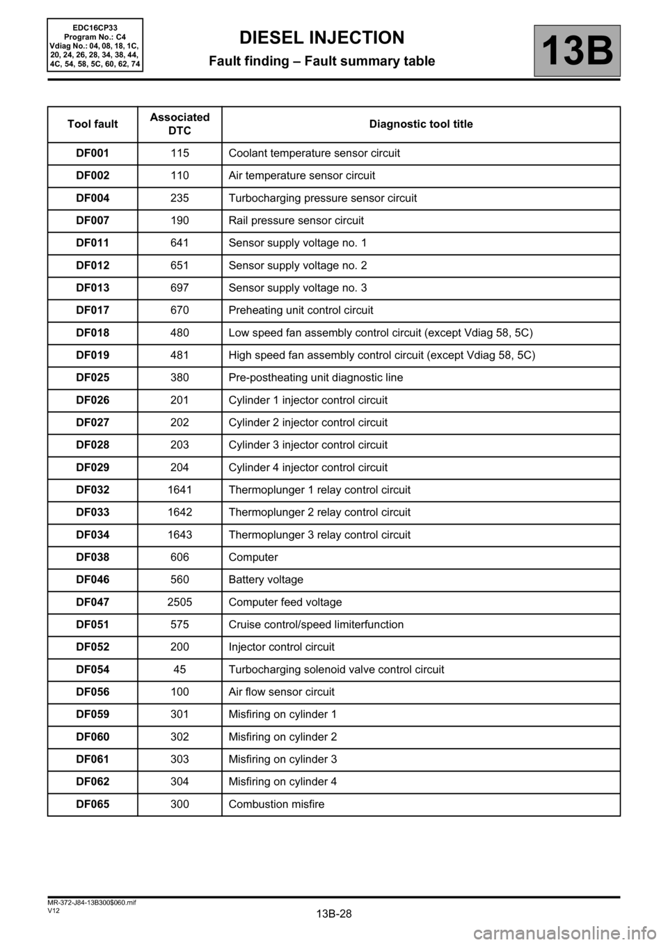
Tool faultAssociated
DTCDiagnostic tool title
DF001115 Coolant temperature sensor circuit
DF002110 Air temperature sensor circuit
DF004235 Turbocharging pressure sensor circuit
DF007190 Rail pressure sensor circuit
DF011641 Sensor supply voltage no. 1
DF012651 Sensor supply voltage no. 2
DF013697 Sensor supply voltage no. 3
DF017670 Preheating unit control circuit
DF018480 Low speed fan assembly control circuit (except Vdiag 58, 5C)
DF019481 High speed fan assembly control circuit (except Vdiag 58, 5C)
DF025380 Pre-postheating unit diagnostic line
DF026201 Cylinder 1 injector control circuit
DF027202 Cylinder 2 injector control circuit
DF028203 Cylinder 3 injector control circuit
DF029204 Cylinder 4 injector control circuit
DF0321641 Thermoplunger 1 relay control circuit
DF0331642 Thermoplunger 2 relay control circuit
DF0341643 Thermoplunger 3 relay control circuit
DF038606 Computer
DF046560 Battery voltage
DF0472505 Computer feed voltage
DF051575 Cruise control/speed limiterfunction
DF052200 Injector control circuit
DF05445 Turbocharging solenoid valve control circuit
DF056100 Air flow sensor circuit
DF059301 Misfiring on cylinder 1
DF060302 Misfiring on cylinder 2
DF061303 Misfiring on cylinder 3
DF062304 Misfiring on cylinder 4
DF065300 Combustion misfire
DIESEL INJECTION
Fault finding – Fault summary table
Page 30 of 510
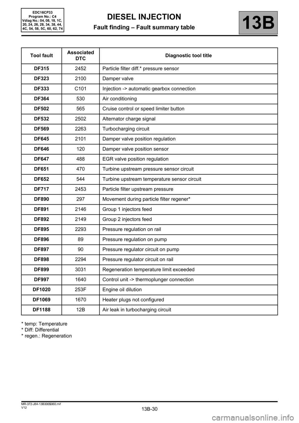
13B-30V12 MR-372-J84-13B300$060.mif
DIESEL INJECTION
Fault finding – Fault summary table13B
EDC16CP33
Program No.: C4
Vdiag No.: 04, 08, 18, 1C,
20, 24, 26, 28, 34, 38, 44,
4C, 54, 58, 5C, 60, 62, 74
* temp: Temperature
* Diff: Differential
* regen.: RegenerationTool faultAssociated
DTCDiagnostic tool title
DF3152452 Particle filter diff.* pressure sensor
DF3232100 Damper valve
DF333C101 Injection -> automatic gearbox connection
DF364530 Air conditioning
DF502565 Cruise control or speed limiter button
DF5322502 Alternator charge signal
DF5692263 Turbocharging circuit
DF6452101 Damper valve position regulation
DF646120 Damper valve position sensor
DF647488 EGR valve position regulation
DF651470 Turbine upstream pressure sensor circuit
DF652544 Turbine upstream temperature sensor circuit
DF7172453 Particle filter upstream pressure
DF890297 Movement during particle filter regener*
DF8912146 Group 1 injectors feed
DF8922149 Group 2 injectors feed
DF8952293 Pressure regulation on rail
DF89689 Pressure regulation on pump
DF89790 Pressure regulator circuit on pump
DF8982294 Pressure regulator circuit on rail
DF8993031 Regeneration temperature limit exceeded
DF9971640 Control unit -> thermoplunger connection
DF1020253F Engine oil dilution
DF10691670 Heater plugs not configured
DF118812B Air leak in turbocharging circuit
Page 40 of 510
13B-40
AFTER REPAIRDeal with any other faults. Clear the fault memory.
Switch off the ignition until the end of the power-latch phase, and carry out a road test
followed by a check with the diagnostic tool.
V12 MR-372-J84-13B300$071.mif
DIESEL INJECTION
Fault finding – Interpretation of faults13B
EDC16CP33
Program No.: C4
Vdiag No.: 04, 08, 18, 1C,
20, 24, 26, 28, 34, 38, 44,
4C, 54, 58, 5C, 60, 62, 74
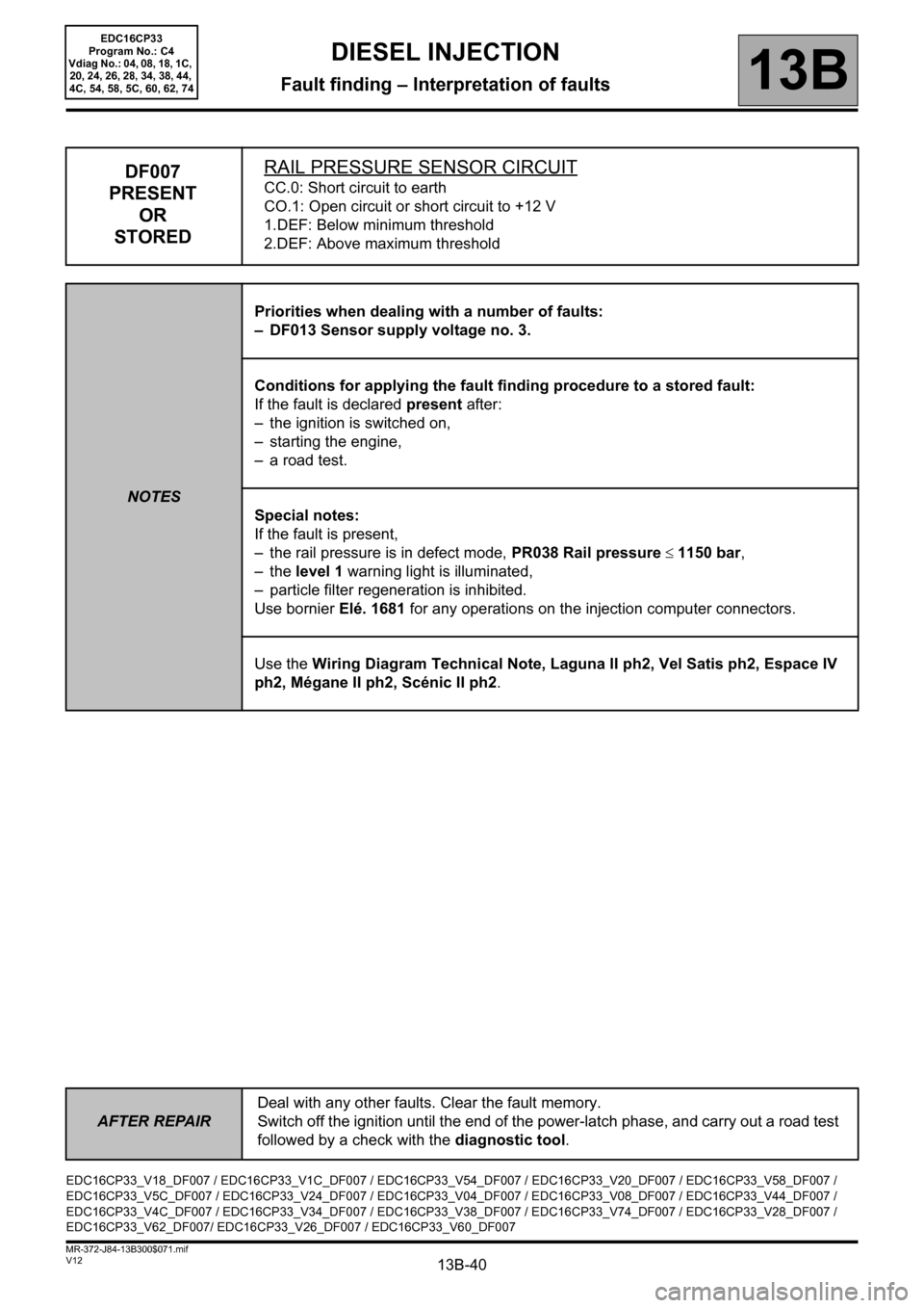
DF007
PRESENT
OR
STOREDRAIL PRESSURE SENSOR CIRCUITCC.0: Short circuit to earth
CO.1: Open circuit or short circuit to +12 V
1.DEF: Below minimum threshold
2.DEF: Above maximum threshold
NOTESPriorities when dealing with a number of faults:
– DF013 Sensor supply voltage no. 3.
Conditions for applying the fault finding procedure to a stored fault:
If the fault is declared present after:
– the ignition is switched on,
– starting the engine,
– a road test.
Special notes:
If the fault is present,
– the rail pressure is in defect mode, PR038 Rail pressure ≤ 1150 bar,
–the level 1 warning light is illuminated,
– particle filter regeneration is inhibited.
Use bornier Elé. 1681 for any operations on the injection computer connectors.
Use the Wiring Diagram Technical Note, Laguna II ph2, Vel Satis ph2, Espace IV
ph2, Mégane II ph2, Scénic II ph2.
EDC16CP33_V18_DF007 / EDC16CP33_V1C_DF007 / EDC16CP33_V54_DF007 / EDC16CP33_V20_DF007 / EDC16CP33_V58_DF007 /
EDC16CP33_V5C_DF007 / EDC16CP33_V24_DF007 / EDC16CP33_V04_DF007 / EDC16CP33_V08_DF007 / EDC16CP33_V44_DF007 /
EDC16CP33_V4C_DF007 / EDC16CP33_V34_DF007 / EDC16CP33_V38_DF007 / EDC16CP33_V74_DF007 / EDC16CP33_V28_DF007 /
EDC16CP33_V62_DF007/ EDC16CP33_V26_DF007 / EDC16CP33_V60_DF007
Page 41 of 510

13B-41
AFTER REPAIRDeal with any other faults. Clear the fault memory.
Switch off the ignition until the end of the power-latch phase, and carry out a road test
followed by a check with the diagnostic tool.
V12 MR-372-J84-13B300$071.mif
DIESEL INJECTION
Fault finding – Interpretation of faults13B
EDC16CP33
Program No.: C4
Vdiag No.: 04, 08, 18, 1C,
20, 24, 26, 28, 34, 38, 44,
4C, 54, 58, 5C, 60, 62, 74
DF007
CONTINUED 1
CC.0NOTESNone.
Check the condition of the rail pressure sensor connector (see Wiring Diagram Technical Note, Laguna II ph2,
Vel Satis ph2, Espace IV ph2, Mégane II ph2, Scénic II ph2, component code 1032).
Check the condition of the engine management computer connector (see Wiring Diagram Technical Note,
Laguna II ph2, Vel Satis ph2, Espace IV ph2, Mégane II ph2, Scénic II ph2, component code 120).
If the connector or connectors are faulty and if there is a repair procedure (see Technical Note 6015A, Electrical
wiring repair, Wiring: Precautions for repair), repair the connector, otherwise replace the wiring.
Check the continuity of the following connection:
•3LX between components 120 and 1032.
Check the insulation to earth of the following connection:
•3LY between components 120 and 1032.
If the connection or connections are faulty and there is a repair procedure (see Technical Note 6015A, Electrical
wiring repair, Wiring: Precautions for repair), repair the wiring, otherwise replace it.
If the wiring of the particle filter downstream temperature sensor, component code 1288, is present (with or without
the sensor being present), check the electrical insulation in relation to + 12 V between the following connections:
–3XU between components 120 and 1288,
–3TG between components 120 and 1288.
If the connection or connections are faulty and there is a repair procedure (see Technical Note 6015A, Electrical
wiring repair, Wiring: Precautions for repair), repair the wiring, otherwise replace it.
If the fault is still present, contact the Techline.
Page 42 of 510
13B-42
AFTER REPAIRDeal with any other faults. Clear the fault memory.
Switch off the ignition until the end of the power-latch phase, and carry out a road test
followed by a check with the diagnostic tool.
V12 MR-372-J84-13B300$071.mif
DIESEL INJECTION
Fault finding – Interpretation of faults13B
EDC16CP33
Program No.: C4
Vdiag No.: 04, 08, 18, 1C,
20, 24, 26, 28, 34, 38, 44,
4C, 54, 58, 5C, 60, 62, 74
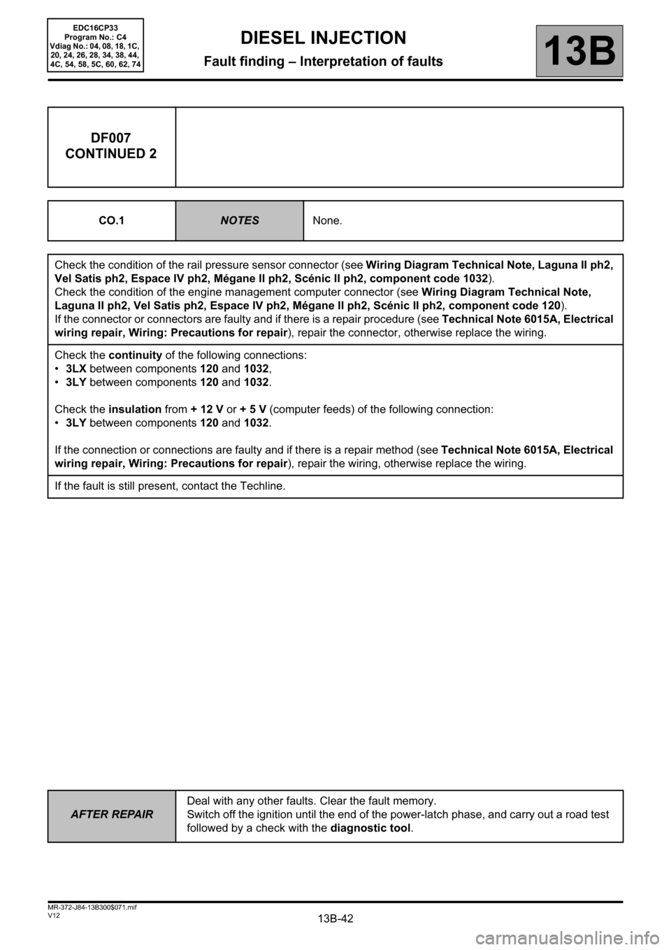
DF007
CONTINUED 2
CO.1NOTESNone.
Check the condition of the rail pressure sensor connector (see Wiring Diagram Technical Note, Laguna II ph2,
Vel Satis ph2, Espace IV ph2, Mégane II ph2, Scénic II ph2, component code 1032).
Check the condition of the engine management computer connector (see Wiring Diagram Technical Note,
Laguna II ph2, Vel Satis ph2, Espace IV ph2, Mégane II ph2, Scénic II ph2, component code 120).
If the connector or connectors are faulty and if there is a repair procedure (see Technical Note 6015A, Electrical
wiring repair, Wiring: Precautions for repair), repair the connector, otherwise replace the wiring.
Check the continuity of the following connections:
•3LX between components 120 and 1032,
•3LY between components 120 and 1032.
Check the insulation from + 12 V or + 5 V (computer feeds) of the following connection:
•3LY between components 120 and 1032.
If the connection or connections are faulty and if there is a repair method (see Technical Note 6015A, Electrical
wiring repair, Wiring: Precautions for repair), repair the wiring, otherwise replace the wiring.
If the fault is still present, contact the Techline.
Page 43 of 510
13B-43
AFTER REPAIRDeal with any other faults. Clear the fault memory.
Switch off the ignition until the end of the power-latch phase, and carry out a road test
followed by a check with the diagnostic tool.
V12 MR-372-J84-13B300$071.mif
DIESEL INJECTION
Fault finding – Interpretation of faults13B
EDC16CP33
Program No.: C4
Vdiag No.: 04, 08, 18, 1C,
20, 24, 26, 28, 34, 38, 44,
4C, 54, 58, 5C, 60, 62, 74
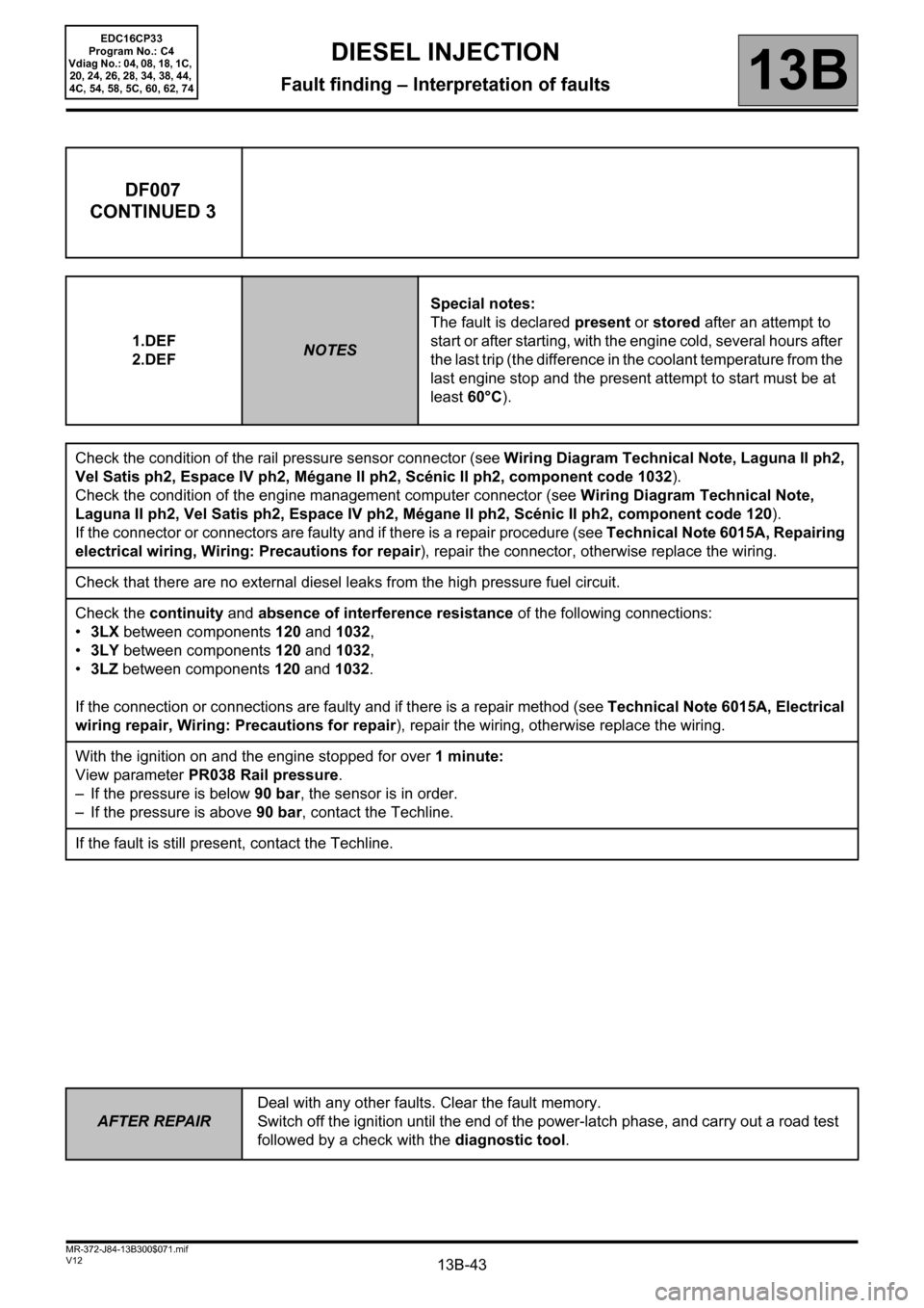
DF007
CONTINUED 3
1.DEF
2.DEFNOTESSpecial notes:
The fault is declared present or stored after an attempt to
start or after starting, with the engine cold, several hours after
the last trip (the difference in the coolant temperature from the
last engine stop and the present attempt to start must be at
least 60°C).
Check the condition of the rail pressure sensor connector (see Wiring Diagram Technical Note, Laguna II ph2,
Vel Satis ph2, Espace IV ph2, Mégane II ph2, Scénic II ph2, component code 1032).
Check the condition of the engine management computer connector (see Wiring Diagram Technical Note,
Laguna II ph2, Vel Satis ph2, Espace IV ph2, Mégane II ph2, Scénic II ph2, component code 120).
If the connector or connectors are faulty and if there is a repair procedure (see Technical Note 6015A, Repairing
electrical wiring, Wiring: Precautions for repair), repair the connector, otherwise replace the wiring.
Check that there are no external diesel leaks from the high pressure fuel circuit.
Check the continuity and absence of interference resistance of the following connections:
•3LX between components 120 and 1032,
•3LY between components 120 and 1032,
•3LZ between components 120 and 1032.
If the connection or connections are faulty and if there is a repair method (see Technical Note 6015A, Electrical
wiring repair, Wiring: Precautions for repair), repair the wiring, otherwise replace the wiring.
With the ignition on and the engine stopped for over 1 minute:
View parameter PR038 Rail pressure.
– If the pressure is below 90 bar, the sensor is in order.
– If the pressure is above 90 bar, contact the Techline.
If the fault is still present, contact the Techline.
Page 52 of 510
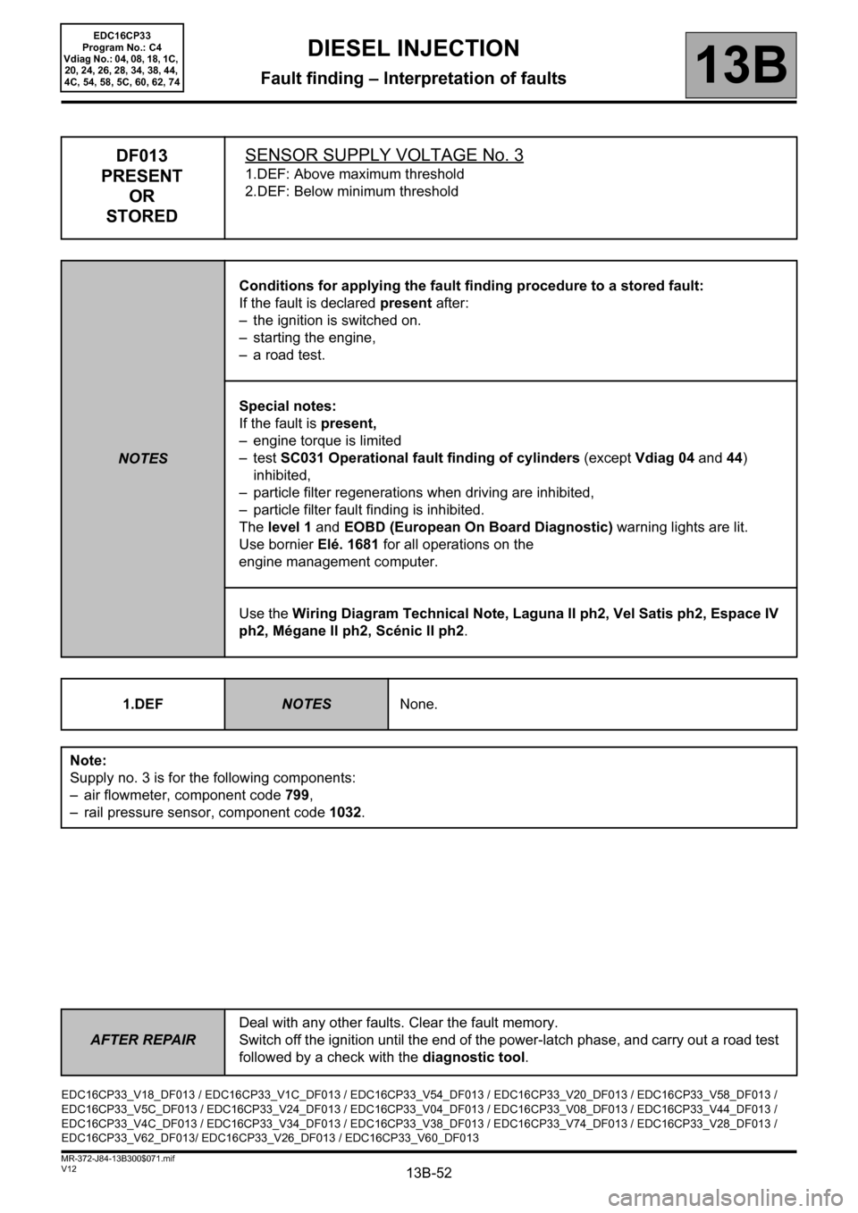
13B-52
AFTER REPAIRDeal with any other faults. Clear the fault memory.
Switch off the ignition until the end of the power-latch phase, and carry out a road test
followed by a check with the diagnostic tool.
V12 MR-372-J84-13B300$071.mif
DIESEL INJECTION
Fault finding – Interpretation of faults13B
EDC16CP33
Program No.: C4
Vdiag No.: 04, 08, 18, 1C,
20, 24, 26, 28, 34, 38, 44,
4C, 54, 58, 5C, 60, 62, 74
DF013
PRESENT
OR
STOREDSENSOR SUPPLY VOLTAGE No. 3
1.DEF: Above maximum threshold
2.DEF: Below minimum threshold
NOTESConditions for applying the fault finding procedure to a stored fault:
If the fault is declared present after:
– the ignition is switched on.
– starting the engine,
– a road test.
Special notes:
If the fault is present,
– engine torque is limited
–test SC031 Operational fault finding of cylinders (except Vdiag 04 and 44)
inhibited,
– particle filter regenerations when driving are inhibited,
– particle filter fault finding is inhibited.
The level 1 and EOBD (European On Board Diagnostic) warning lights are lit.
Use bornier Elé. 1681 for all operations on the
engine management computer.
Use the Wiring Diagram Technical Note, Laguna II ph2, Vel Satis ph2, Espace IV
ph2, Mégane II ph2, Scénic II ph2.
1.DEF
NOTESNone.
Note:
Supply no. 3 is for the following components:
– air flowmeter, component code 799,
– rail pressure sensor, component code 1032.
EDC16CP33_V18_DF013 / EDC16CP33_V1C_DF013 / EDC16CP33_V54_DF013 / EDC16CP33_V20_DF013 / EDC16CP33_V58_DF013 /
EDC16CP33_V5C_DF013 / EDC16CP33_V24_DF013 / EDC16CP33_V04_DF013 / EDC16CP33_V08_DF013 / EDC16CP33_V44_DF013 /
EDC16CP33_V4C_DF013 / EDC16CP33_V34_DF013 / EDC16CP33_V38_DF013 / EDC16CP33_V74_DF013 / EDC16CP33_V28_DF013 /
EDC16CP33_V62_DF013/ EDC16CP33_V26_DF013 / EDC16CP33_V60_DF013