recorded RENAULT SCENIC 2012 J95 / 3.G Engine And Peripherals EDC16CP33 Workshop Manual
[x] Cancel search | Manufacturer: RENAULT, Model Year: 2012, Model line: SCENIC, Model: RENAULT SCENIC 2012 J95 / 3.GPages: 510, PDF Size: 2.98 MB
Page 318 of 510
13B-318V12 MR-372-J84-13B300$102.mif
DIESEL INJECTION
Fault finding – Interpretation of statuses13B
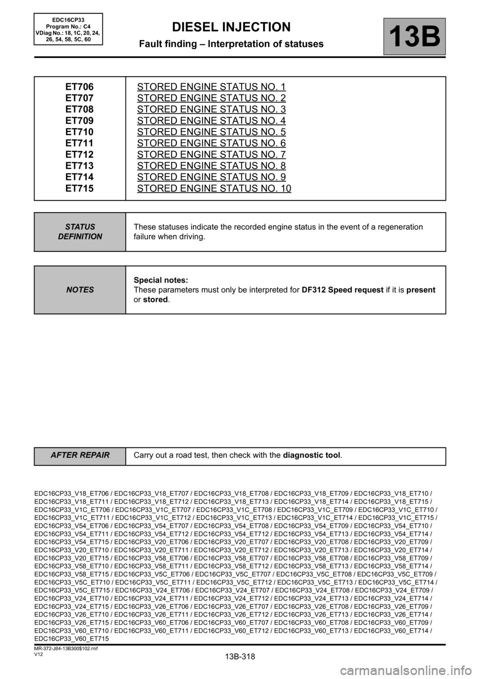
ET706
ET707
ET708
ET709
ET710
ET711
ET712
ET713
ET714
ET715STORED ENGINE STATUS NO. 1
STORED ENGINE STATUS NO. 2
STORED ENGINE STATUS NO. 3
STORED ENGINE STATUS NO. 4
STORED ENGINE STATUS NO. 5
STORED ENGINE STATUS NO. 6
STORED ENGINE STATUS NO. 7
STORED ENGINE STATUS NO. 8
STORED ENGINE STATUS NO. 9
STORED ENGINE STATUS NO. 10
STATUS
DEFINITIONThese statuses indicate the recorded engine status in the event of a regeneration
failure when driving.
NOTESSpecial notes:
These parameters must only be interpreted for DF312 Speed request if it is present
or stored.
EDC16CP33_V18_ET706 / EDC16CP33_V18_ET707 / EDC16CP33_V18_ET708 / EDC16CP33_V18_ET709 / EDC16CP33_V18_ET710 /
EDC16CP33_V18_ET711 / EDC16CP33_V18_ET712 / EDC16CP33_V18_ET713 / EDC16CP33_V18_ET714 / EDC16CP33_V18_ET715 /
EDC16CP33_V1C_ET706 / EDC16CP33_V1C_ET707 / EDC16CP33_V1C_ET708 / EDC16CP33_V1C_ET709 / EDC16CP33_V1C_ET710 /
EDC16CP33_V1C_ET711 / EDC16CP33_V1C_ET712 / EDC16CP33_V1C_ET713 / EDC16CP33_V1C_ET714 / EDC16CP33_V1C_ET715 /
EDC16CP33_V54_ET706 / EDC16CP33_V54_ET707 / EDC16CP33_V54_ET708 / EDC16CP33_V54_ET709 / EDC16CP33_V54_ET710 /
EDC16CP33_V54_ET711 / EDC16CP33_V54_ET712 / EDC16CP33_V54_ET712 / EDC16CP33_V54_ET713 / EDC16CP33_V54_ET714 /
EDC16CP33_V54_ET715 / EDC16CP33_V20_ET706 / EDC16CP33_V20_ET707 / EDC16CP33_V20_ET708 / EDC16CP33_V20_ET709 /
EDC16CP33_V20_ET710 / EDC16CP33_V20_ET711 / EDC16CP33_V20_ET712 / EDC16CP33_V20_ET713 / EDC16CP33_V20_ET714 /
EDC16CP33_V20_ET715 / EDC16CP33_V58_ET706 / EDC16CP33_V58_ET707 / EDC16CP33_V58_ET708 / EDC16CP33_V58_ET709 /
EDC16CP33_V58_ET710 / EDC16CP33_V58_ET711 / EDC16CP33_V58_ET712 / EDC16CP33_V58_ET713 / EDC16CP33_V58_ET714 /
EDC16CP33_V58_ET715 / EDC16CP33_V5C_ET706 / EDC16CP33_V5C_ET707 / EDC16CP33_V5C_ET708 / EDC16CP33_V5C_ET709 /
EDC16CP33_V5C_ET710 / EDC16CP33_V5C_ET711 / EDC16CP33_V5C_ET712 / EDC16CP33_V5C_ET713 / EDC16CP33_V5C_ET714 /
EDC16CP33_V5C_ET715 / EDC16CP33_V24_ET706 / EDC16CP33_V24_ET707 / EDC16CP33_V24_ET708 / EDC16CP33_V24_ET709 /
EDC16CP33_V24_ET710 / EDC16CP33_V24_ET711 / EDC16CP33_V24_ET712 / EDC16CP33_V24_ET713 / EDC16CP33_V24_ET714 /
EDC16CP33_V24_ET715 / EDC16CP33_V26_ET706 / EDC16CP33_V26_ET707 / EDC16CP33_V26_ET708 / EDC16CP33_V26_ET709 /
EDC16CP33_V26_ET710 / EDC16CP33_V26_ET711 / EDC16CP33_V26_ET712 / EDC16CP33_V26_ET713 / EDC16CP33_V26_ET714 /
EDC16CP33_V26_ET715 / EDC16CP33_V60_ET706 / EDC16CP33_V60_ET707 / EDC16CP33_V60_ET708 / EDC16CP33_V60_ET709 /
EDC16CP33_V60_ET710 / EDC16CP33_V60_ET711 / EDC16CP33_V60_ET712 / EDC16CP33_V60_ET713 / EDC16CP33_V60_ET714 /
EDC16CP33_V60_ET715
EDC16CP33
Program No.: C4
VDiag No.: 18, 1C, 20, 24,
26, 54, 58, 5C, 60
AFTER REPAIRCarry out a road test, then check with the diagnostic tool.
Page 319 of 510
13B-319V12 MR-372-J84-13B300$102.mif
DIESEL INJECTION
Fault finding – Interpretation of statuses13B
ET706
ET707
ET708
ET709
ET710
ET711
ET712
ET713
ET714
ET715
CONTINUED
Conformity check: Engine stopped and ignition on, or engine running, and engine coolant
temperature > 80°C
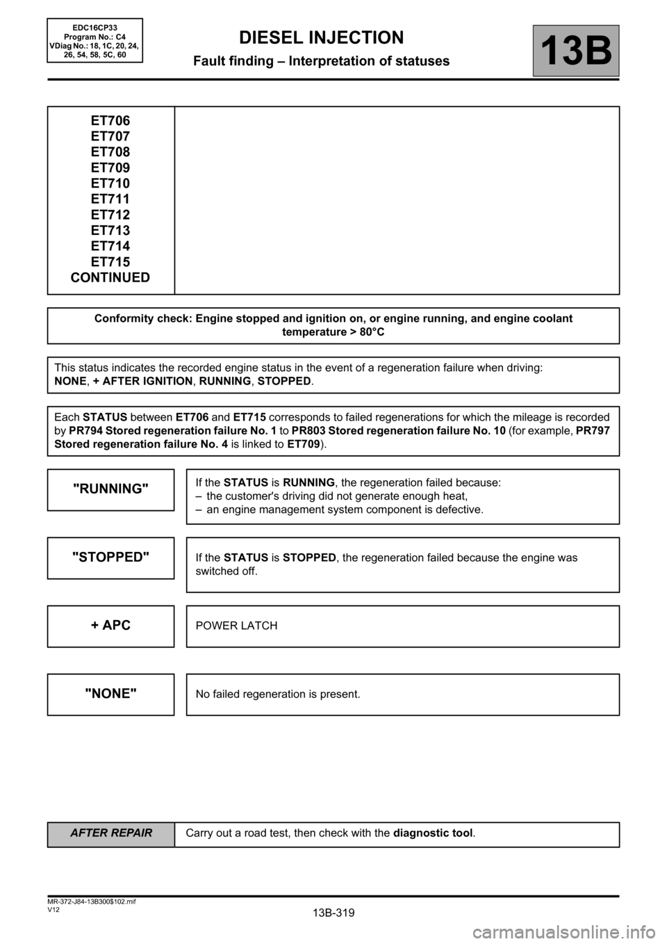
This status indicates the recorded engine status in the event of a regeneration failure when driving:
NONE, + AFTER IGNITION, RUNNING, STOPPED.
Each STATUS between ET706 and ET715 corresponds to failed regenerations for which the mileage is recorded
by PR794 Stored regeneration failure No. 1 to PR803 Stored regeneration failure No. 10 (for example, PR797
Stored regeneration failure No. 4 is linked to ET709).
"RUNNING"If the STATUS is RUNNING, the regeneration failed because:
– the customer's driving did not generate enough heat,
– an engine management system component is defective.
"STOPPED"If the STATUS is STOPPED, the regeneration failed because the engine was
switched off.
+ APCPOWER LATCH
"NONE"No failed regeneration is present.
EDC16CP33
Program No.: C4
VDiag No.: 18, 1C, 20, 24,
26, 54, 58, 5C, 60
AFTER REPAIRCarry out a road test, then check with the diagnostic tool.
Page 407 of 510
13B-407V12 MR-372-J84-13B300$122.mif
DIESEL INJECTION
Fault finding – Interpretation of parameters13B
PR794
PR795
PR796
PR797
PR798
PR799
PR800
PR801
PR802
PR803
CONTINUED
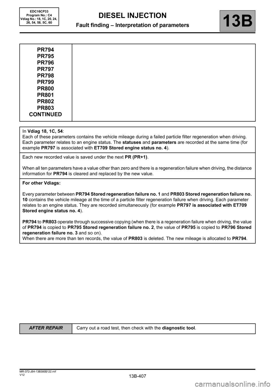
In Vdiag 18, 1C, 54:
Each of these parameters contains the vehicle mileage during a failed particle filter regeneration when driving.
Each parameter relates to an engine status. The statuses and parameters are recorded at the same time (for
example PR797 is associated with ET709 Stored engine status no. 4).
Each new recorded value is saved under the next PR (PR+1).
When all ten parameters have a value other than zero and there is a regeneration failure when driving, the distance
information for PR794 is cleared and replaced by the new value.
For other Vdiags:
Every parameter between PR794 Stored regeneration failure no. 1 and PR803 Stored regeneration failure no.
10 contains the vehicle mileage at the time of a particle filter regeneration failure when driving. Each parameter
relates to an engine status. They are recorded simultaneously (for example PR797 is associated with ET709
Stored engine status no. 4).
PR794 to PR803 operate through successive copying (when there is a regeneration failure when driving, the value
of PR794 is copied to PR795 Stored regeneration failure no. 2, the value of PR795 is copied to PR796 Stored
regeneration failure no. 3 and so on).
When there are more than ten records, the value of PR803 is deleted. The new mileage is allocated to PR794.
EDC16CP33
Program No.: C4
Vdiag No.: 18, 1C, 20, 24,
26, 54, 58, 5C, 60
AFTER REPAIRCarry out a road test, then check with the diagnostic tool.
Page 409 of 510
13B-409V12 MR-372-J84-13B300$122.mif
DIESEL INJECTION
Fault finding – Interpretation of parameters13B
rege*: Regeneration
PR816
PR817
PR818
PR819
PR820
PR821
PR822
PR823
PR824
PR825
CONTINUED
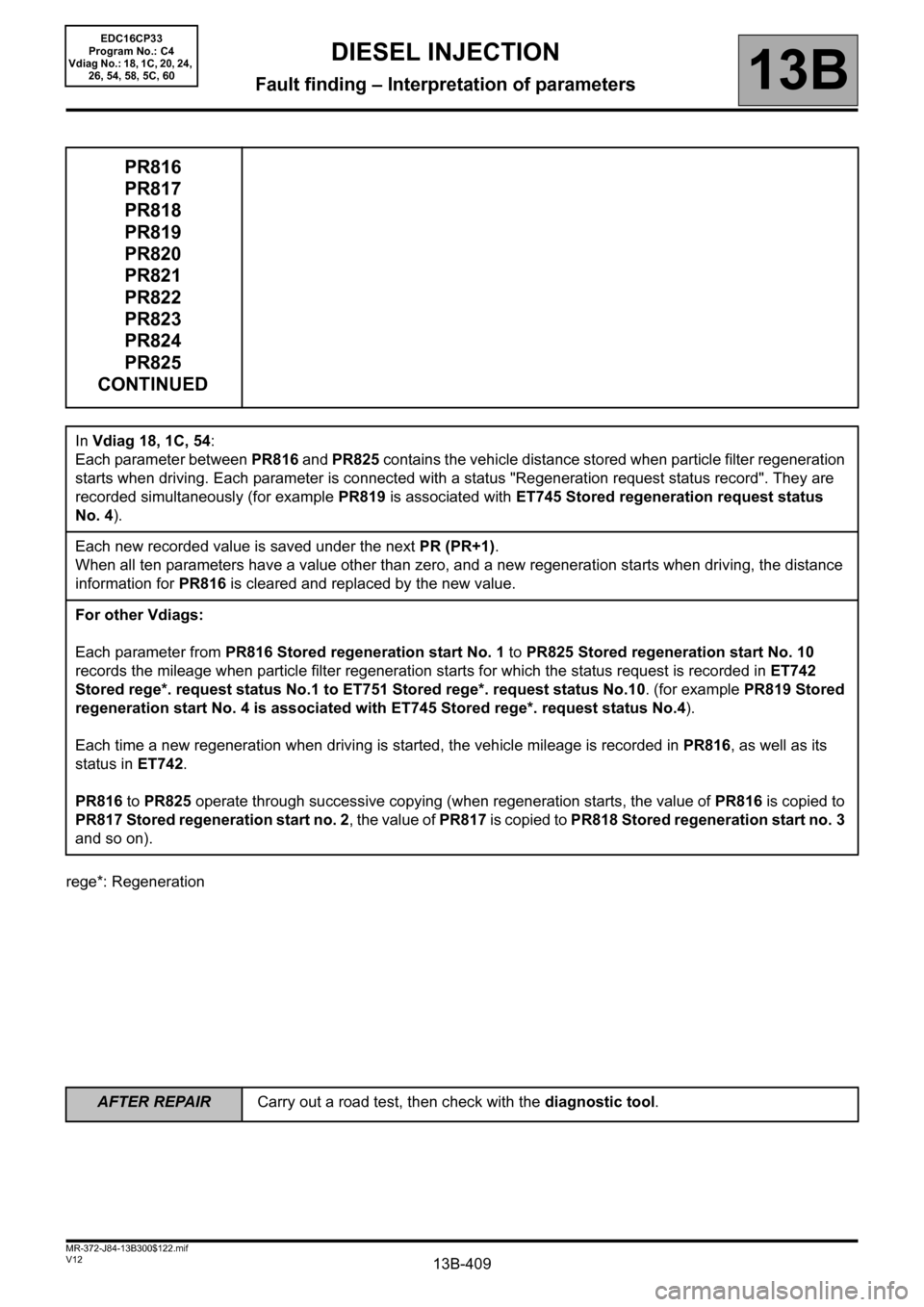
In Vdiag 18, 1C, 54:
Each parameter between PR816 and PR825 contains the vehicle distance stored when particle filter regeneration
starts when driving. Each parameter is connected with a status "Regeneration request status record". They are
recorded simultaneously (for example PR819 is associated with ET745 Stored regeneration request status
No. 4).
Each new recorded value is saved under the next PR (PR+1).
When all ten parameters have a value other than zero, and a new regeneration starts when driving, the distance
information for PR816 is cleared and replaced by the new value.
For other Vdiags:
Each parameter from PR816 Stored regeneration start No. 1 to PR825 Stored regeneration start No. 10
records the mileage when particle filter regeneration starts for which the status request is recorded in ET742
Stored rege*. request status No.1 to ET751 Stored rege*. request status No.10. (for example PR819 Stored
regeneration start No. 4 is associated with ET745 Stored rege*. request status No.4).
Each time a new regeneration when driving is started, the vehicle mileage is recorded in PR816, as well as its
status in ET742.
PR816 to PR825 operate through successive copying (when regeneration starts, the value of PR816 is copied to
PR817 Stored regeneration start no. 2, the value of PR817 is copied to PR818 Stored regeneration start no. 3
and so on).
AFTER REPAIRCarry out a road test, then check with the diagnostic tool.
EDC16CP33
Program No.: C4
Vdiag No.: 18, 1C, 20, 24,
26, 54, 58, 5C, 60
Page 455 of 510
13B-455V12 MR-372-J84-13B300$150.mif
DIESEL INJECTION
Fault finding – Interpretation of commands13B
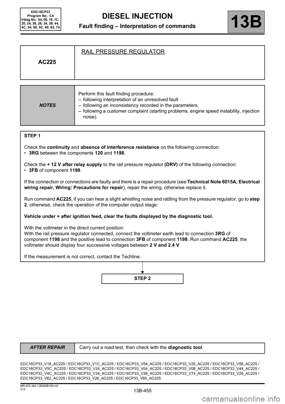
AC225RAIL PRESSURE REGULATOR
NOTESPerform this fault finding procedure:
– following interpretation of an unresolved fault
– following an inconsistency recorded in the parameters,
– following a customer complaint (starting problems, engine speed instability, injection
noise).
STEP 1
Check the continuity and absence of interference resistance on the following connection:
•3RG between the components 120 and 1198.
Check the + 12 V after relay supply to the rail pressure regulator (DRV) of the following connection:
•3FB of component 1198.
If the connection or connections are faulty and there is a repair procedure (see Technical Note 6015A, Electrical
wiring repair, Wiring: Precautions for repair), repair the wiring, otherwise replace it.
Run command AC225, if you can hear a slight whistling noise and rattling from the pressure regulator, go to step
2, otherwise, check the operation of the computer output stage:
Vehicle under + after ignition feed, clear the faults displayed by the diagnostic tool.
With the voltmeter in the direct current position:
With the rail pressure regulator connected, connect the voltmeter earth lead to connection3RG of
component1198 and the positive lead to connection3FB of component1198. Run command AC225, the
voltmeter should display four successive voltages between 2 V and 2.4 V.
If the measurement is not correct, contact the Techline.
STEP 2
EDC16CP33_V18_AC225 / EDC16CP33_V1C_AC225 / EDC16CP33_V54_AC225 / EDC16CP33_V20_AC225 / EDC16CP33_V58_AC225 /
EDC16CP33_V5C_AC225 / EDC16CP33_V24_AC225 / EDC16CP33_V04_AC225 / EDC16CP33_V08_AC225 / EDC16CP33_V44_AC225 /
EDC16CP33_V4C_AC225 / EDC16CP33_V34_AC225 / EDC16CP33_V38_AC225 / EDC16CP33_V74_AC225 / EDC16CP33_V28_AC225 /
EDC16CP33_V62_AC225 / EDC16CP33_V26_AC225 / EDC16CP33_V60_AC225
EDC16CP33
Program No.: C4
Vdiag No.: 04, 08, 18, 1C,
20, 24, 26, 28, 34, 38, 44,
4C, 54, 58, 5C, 60, 62, 74
AFTER REPAIRCarry out a road test, then check with the diagnostic tool.
Page 457 of 510
13B-457V12 MR-372-J84-13B300$150.mif
DIESEL INJECTION
Fault finding – Interpretation of commands13B
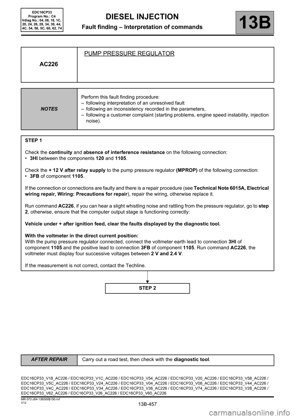
AC226PUMP PRESSURE REGULATOR
NOTESPerform this fault finding procedure:
– following interpretation of an unresolved fault
– following an inconsistency recorded in the parameters,
– following a customer complaint (starting problems, engine speed instability, injection
noise).
STEP 1
Check the continuity and absence of interference resistance on the following connection:
•3HI between the components 120 and 1105.
Check the + 12 V after relay supply to the pump pressure regulator (MPROP) of the following connection:
•3FB of component 1105.
If the connection or connections are faulty and there is a repair procedure (see Technical Note 6015A, Electrical
wiring repair, Wiring: Precautions for repair), repair the wiring, otherwise replace it.
Run command AC226, if you can hear a slight whistling noise and rattling from the pressure regulator, go to step
2, otherwise, ensure that the computer output stage is functioning correctly:
Vehicle under + after ignition feed, clear the faults displayed by the diagnostic tool.
With the voltmeter in the direct current position:
With the pump pressure regulator connected, connect the voltmeter earth lead to connection3HI of
component1105 and the positive lead to connection3FB of component1105. Run command AC226, the
voltmeter must display four successive voltages between 2 V and 2.4 V.
If the measurement is not correct, contact the Techline.
STEP 2
EDC16CP33_V18_AC226 / EDC16CP33_V1C_AC226 / EDC16CP33_V54_AC226 / EDC16CP33_V20_AC226 / EDC16CP33_V58_AC226 /
EDC16CP33_V5C_AC226 / EDC16CP33_V24_AC226 / EDC16CP33_V04_AC226 / EDC16CP33_V08_AC226 / EDC16CP33_V44_AC226 /
EDC16CP33_V4C_AC226 / EDC16CP33_V34_AC226 / EDC16CP33_V38_AC226 / EDC16CP33_V74_AC226 / EDC16CP33_V28_AC226 /
EDC16CP33_V62_AC226 / EDC16CP33_V26_AC226 / EDC16CP33_V60_AC226
EDC16CP33
Program No.: C4
Vdiag No.: 04, 08, 18, 1C,
20, 24, 26, 28, 34, 38, 44,
4C, 54, 58, 5C, 60, 62, 74
AFTER REPAIRCarry out a road test, then check with the diagnostic tool.
Page 459 of 510
13B-459V12 MR-372-J84-13B300$150.mif
DIESEL INJECTION
Fault finding – Interpretation of commands13B
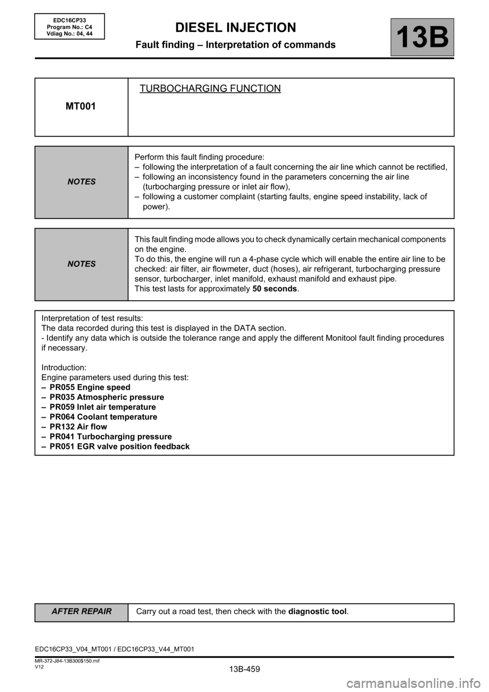
MT001TURBOCHARGING FUNCTION
NOTESPerform this fault finding procedure:
– following the interpretation of a fault concerning the air line which cannot be rectified,
– following an inconsistency found in the parameters concerning the air line
(turbocharging pressure or inlet air flow),
– following a customer complaint (starting faults, engine speed instability, lack of
power).
NOTESThis fault finding mode allows you to check dynamically certain mechanical components
on the engine.
To do this, the engine will run a 4-phase cycle which will enable the entire air line to be
checked: air filter, air flowmeter, duct (hoses), air refrigerant, turbocharging pressure
sensor, turbocharger, inlet manifold, exhaust manifold and exhaust pipe.
This test lasts for approximately 50 seconds.
Interpretation of test results:
The data recorded during this test is displayed in the DATA section.
- Identify any data which is outside the tolerance range and apply the different Monitool fault finding procedures
if necessary.
Introduction:
Engine parameters used during this test:
– PR055 Engine speed
– PR035 Atmospheric pressure
– PR059 Inlet air temperature
– PR064 Coolant temperature
–PR132 Air flow
– PR041 Turbocharging pressure
– PR051 EGR valve position feedback
EDC16CP33_V04_MT001 / EDC16CP33_V44_MT001
EDC16CP33
Program No.: C4
Vdiag No.: 04, 44
AFTER REPAIRCarry out a road test, then check with the diagnostic tool.
Page 460 of 510
13B-460V12 MR-372-J84-13B300$150.mif
DIESEL INJECTION
Fault finding – Interpretation of commands13B
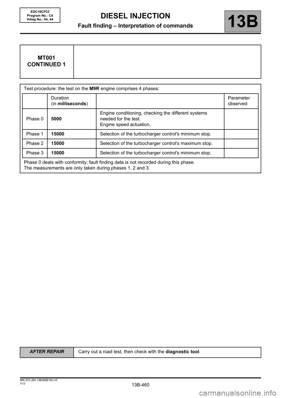
MT001
CONTINUED 1
Test procedure: the test on the M9R engine comprises 4 phases:
Duration
(in milliseconds)Parameter
observed
Phase 05000Engine conditioning, checking the different systems
needed for the test.
Engine speed actuation,
Phase 115000Selection of the turbocharger control's minimum stop.
Phase 215000Selection of the turbocharger control's maximum stop.
Phase 315000Selection of the turbocharger control's minimum stop.
Phase 0 deals with conformity; fault finding data is not recorded during this phase.
The measurements are only taken during phases 1, 2 and 3.
EDC16CP33
Program No.: C4
Vdiag No.: 04, 44
AFTER REPAIRCarry out a road test, then check with the diagnostic tool.