steering RENAULT SCENIC 2012 J95 / 3.G Engine And Peripherals EDC16CP33 Workshop Manual
[x] Cancel search | Manufacturer: RENAULT, Model Year: 2012, Model line: SCENIC, Model: RENAULT SCENIC 2012 J95 / 3.GPages: 510, PDF Size: 2.98 MB
Page 9 of 510
13B-9V12 MR-372-J84-13B300$020.mif
DIESEL INJECTION
Fault finding – Cleanliness guidelines13B
EDC16CP33
Program No.: C4
Vdiag No.: 04, 08, 18, 1C,
20, 24, 26, 28, 34, 38, 44,
4C, 54, 58, 5C, 60, 62, 74
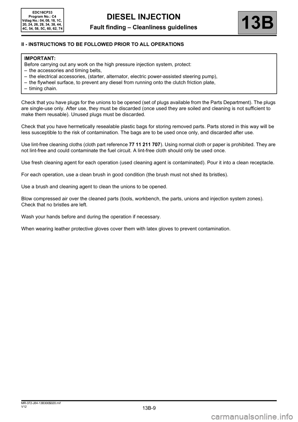
II - INSTRUCTIONS TO BE FOLLOWED PRIOR TO ALL OPERATIONS
Check that you have plugs for the unions to be opened (set of plugs available from the Parts Department). The plugs
are single-use only. After use, they must be discarded (once used they are soiled and cleaning is not sufficient to
make them reusable). Unused plugs must be discarded.
Check that you have hermetically resealable plastic bags for storing removed parts. Parts stored in this way will be
less susceptible to the risk of contamination. The bags are to be used once only, and discarded after use.
Use lint-free cleaning cloths (cloth part reference 77 11 211 707). Using normal cloth or paper is prohibited. They are
not lint-free and could contaminate the fuel circuit. A lint-free cloth should only be used once.
Use fresh cleaning agent for each operation (used cleaning agent is contaminated). Pour it into a clean receptacle.
For each operation, use a clean brush in good condition (the brush must not shed its bristles).
Use a brush and cleaning agent to clean the unions to be opened.
Blow compressed air over the cleaned parts (tools, workbench, the parts, unions and injection system zones).
Check that no bristles are left.
Wash your hands before and during the operation if necessary.
When wearing leather protective gloves cover them with latex gloves to prevent contamination. IMPORTANT:
Before carrying out any work on the high pressure injection system, protect:
– the accessories and timing belts,
– the electrical accessories, (starter, alternator, electric power-assisted steering pump),
– the flywheel surface, to prevent any diesel from running onto the clutch friction plate,
– timing chain.
Page 47 of 510
13B-47
AFTER REPAIRDeal with any other faults. Clear the fault memory.
Switch off the ignition until the end of the power-latch phase, and carry out a road test
followed by a check with the diagnostic tool.
V12 MR-372-J84-13B300$071.mif
DIESEL INJECTION
Fault finding – Interpretation of faults13B
EDC16CP33
Program No.: C4
Vdiag No.: 04, 08, 18, 1C,
20, 24, 26, 28, 34, 38, 44,
4C, 54, 58, 5C, 60, 62, 74
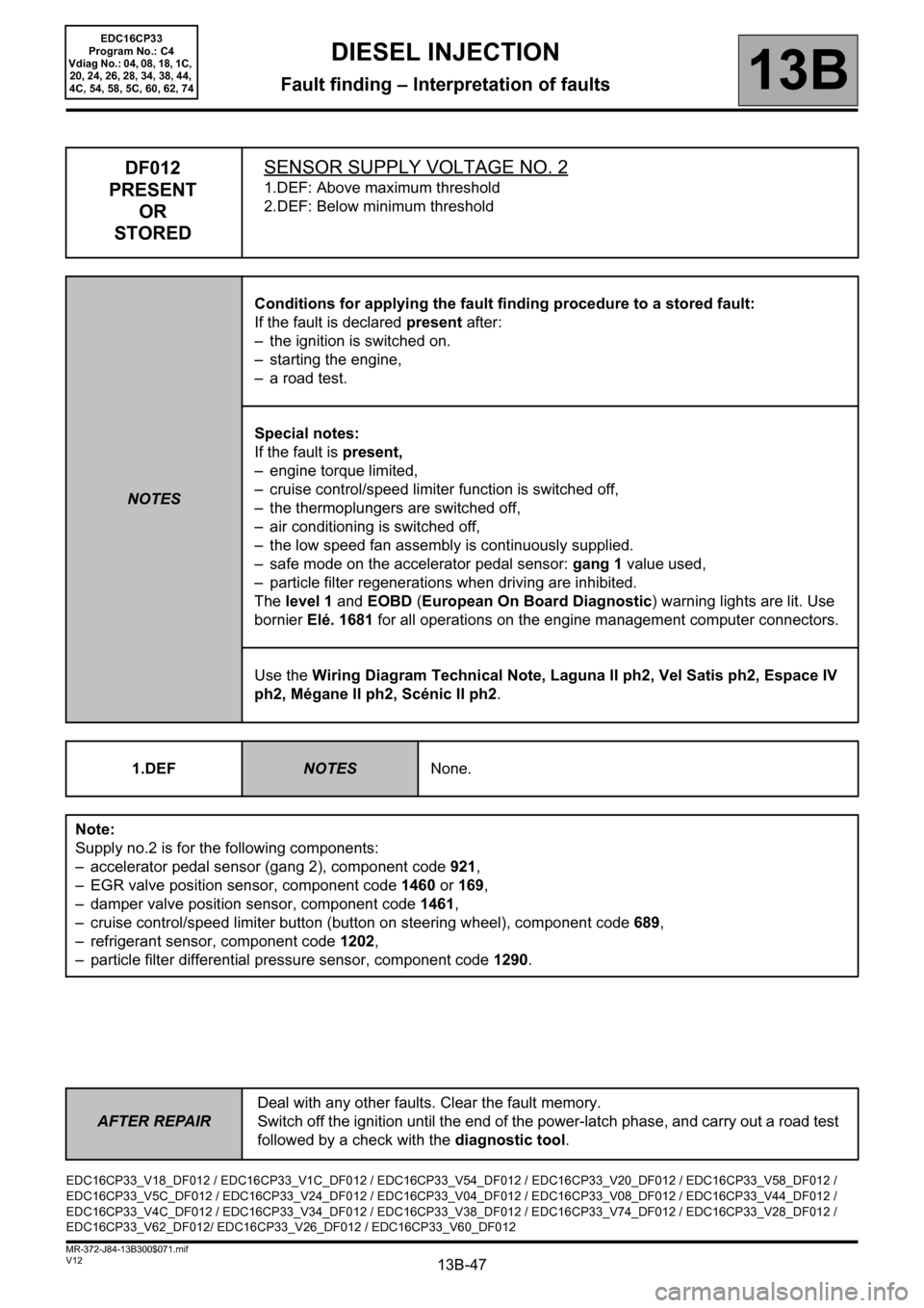
DF012
PRESENT
OR
STOREDSENSOR SUPPLY VOLTAGE NO. 2
1.DEF: Above maximum threshold
2.DEF: Below minimum threshold
NOTESConditions for applying the fault finding procedure to a stored fault:
If the fault is declared present after:
– the ignition is switched on.
– starting the engine,
– a road test.
Special notes:
If the fault is present,
– engine torque limited,
– cruise control/speed limiter function is switched off,
– the thermoplungers are switched off,
– air conditioning is switched off,
– the low speed fan assembly is continuously supplied.
– safe mode on the accelerator pedal sensor: gang 1 value used,
– particle filter regenerations when driving are inhibited.
The level 1 and EOBD (European On Board Diagnostic) warning lights are lit. Use
bornier Elé. 1681 for all operations on the engine management computer connectors.
Use the Wiring Diagram Technical Note, Laguna II ph2, Vel Satis ph2, Espace IV
ph2, Mégane II ph2, Scénic II ph2.
1.DEF
NOTESNone.
Note:
Supply no.2 is for the following components:
– accelerator pedal sensor (gang 2), component code 921,
– EGR valve position sensor, component code 1460 or 169,
– damper valve position sensor, component code 1461,
– cruise control/speed limiter button (button on steering wheel), component code 689,
– refrigerant sensor, component code 1202,
– particle filter differential pressure sensor, component code 1290.
EDC16CP33_V18_DF012 / EDC16CP33_V1C_DF012 / EDC16CP33_V54_DF012 / EDC16CP33_V20_DF012 / EDC16CP33_V58_DF012 /
EDC16CP33_V5C_DF012 / EDC16CP33_V24_DF012 / EDC16CP33_V04_DF012 / EDC16CP33_V08_DF012 / EDC16CP33_V44_DF012 /
EDC16CP33_V4C_DF012 / EDC16CP33_V34_DF012 / EDC16CP33_V38_DF012 / EDC16CP33_V74_DF012 / EDC16CP33_V28_DF012 /
EDC16CP33_V62_DF012/ EDC16CP33_V26_DF012 / EDC16CP33_V60_DF012
Page 50 of 510
13B-50
AFTER REPAIRDeal with any other faults. Clear the fault memory.
Switch off the ignition until the end of the power-latch phase, and carry out a road test
followed by a check with the diagnostic tool.
V12 MR-372-J84-13B300$071.mif
DIESEL INJECTION
Fault finding – Interpretation of faults13B
EDC16CP33
Program No.: C4
Vdiag No.: 04, 08, 18, 1C,
20, 24, 26, 28, 34, 38, 44,
4C, 54, 58, 5C, 60, 62, 74
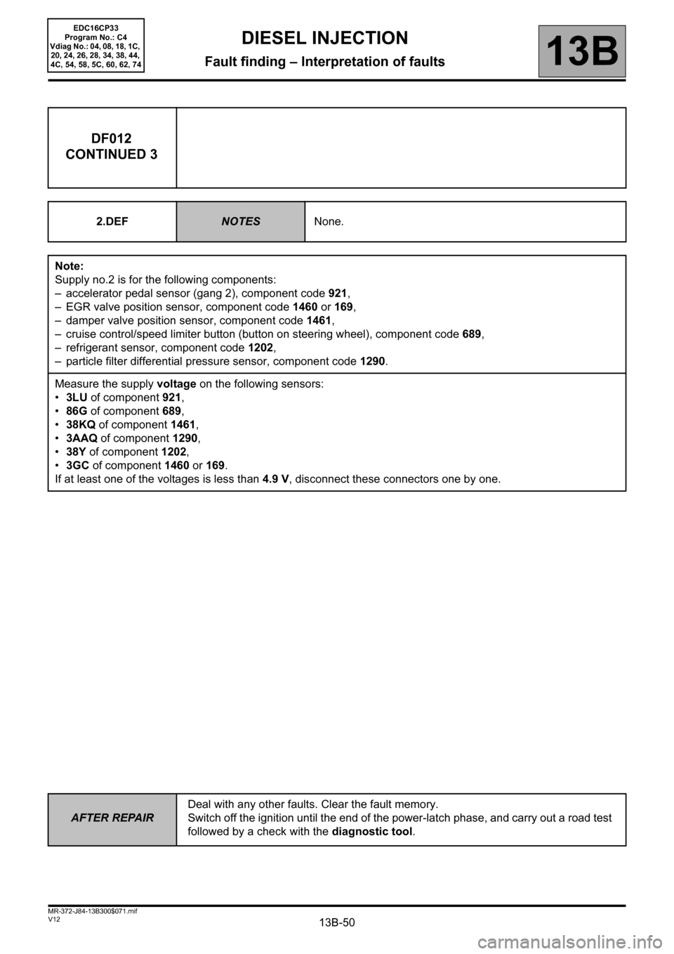
DF012
CONTINUED 3
2.DEFNOTESNone.
Note:
Supply no.2 is for the following components:
– accelerator pedal sensor (gang 2), component code 921,
– EGR valve position sensor, component code 1460 or 169,
– damper valve position sensor, component code 1461,
– cruise control/speed limiter button (button on steering wheel), component code 689,
– refrigerant sensor, component code 1202,
– particle filter differential pressure sensor, component code 1290.
Measure the supply voltage on the following sensors:
•3LU of component 921,
•86G of component 689,
•38KQ of component 1461,
•3AAQ of component 1290,
•38Y of component 1202,
•3GC of component 1460 or 169.
If at least one of the voltages is less than 4.9 V, disconnect these connectors one by one.
Page 107 of 510
13B-107
AFTER REPAIRDeal with any other faults. Clear the fault memory.
Switch off the ignition until the end of the power-latch phase, and carry out a road test
followed by a check with the diagnostic tool.
V12 MR-372-J84-13B300$072.mif
DIESEL INJECTION
Fault finding – Interpretation of faults13B
EDC16CP33
Program No.: C4
Vdiag No.: 04, 08, 18, 1C,
20, 24, 26, 28, 34, 38, 44,
4C, 54, 58, 5C, 60, 62, 74
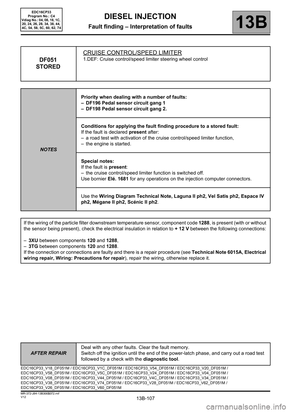
DF051
STOREDCRUISE CONTROL/SPEED LIMITER1.DEF: Cruise control/speed limiter steering wheel control
NOTESPriority when dealing with a number of faults:
– DF196 Pedal sensor circuit gang 1
– DF198 Pedal sensor circuit gang 2.
Conditions for applying the fault finding procedure to a stored fault:
If the fault is declared present after:
– a road test with activation of the cruise control/speed limiter function,
– the engine is started.
Special notes:
If the fault is present:
– the cruise control/speed limiter function is switched off.
Use bornier Elé. 1681 for any operations on the injection computer connectors.
Use the Wiring Diagram Technical Note, Laguna II ph2, Vel Satis ph2, Espace IV
ph2, Mégane II ph2, Scénic II ph2.
If the wiring of the particle filter downstream temperature sensor, component code 1288, is present (with or without
the sensor being present), check the electrical insulation in relation to + 12 V between the following connections:
–3XU between components 120 and 1288,
–3TG between components 120 and 1288.
If the connection or connections are faulty and there is a repair procedure (see Technical Note 6015A, Electrical
wiring repair, Wiring: Precautions for repair), repair the wiring, otherwise replace it.
EDC16CP33_V18_DF051M / EDC16CP33_V1C_DF051M / EDC16CP33_V54_DF051M / EDC16CP33_V20_DF051M /
EDC16CP33_V58_DF051M / EDC16CP33_V5C_DF051M / EDC16CP33_V24_DF051M / EDC16CP33_V04_DF051M /
EDC16CP33_V08_DF051M / EDC16CP33_V44_DF051M / EDC16CP33_V4C_DF051M / EDC16CP33_V34_DF051M /
EDC16CP33_V38_DF051M / EDC16CP33_V74_DF051M / EDC16CP33_V28_DF051M / EDC16CP33_V62_DF051M /
EDC16CP33_V26_DF051M / EDC16CP33_V60_DF051M
Page 108 of 510
13B-108
AFTER REPAIRDeal with any other faults. Clear the fault memory.
Switch off the ignition until the end of the power-latch phase, and carry out a road test
followed by a check with the diagnostic tool.
V12 MR-372-J84-13B300$072.mif
DIESEL INJECTION
Fault finding – Interpretation of faults13B
EDC16CP33
Program No.: C4
Vdiag No.: 04, 08, 18, 1C,
20, 24, 26, 28, 34, 38, 44,
4C, 54, 58, 5C, 60, 62, 74
DF051
CONTINUED
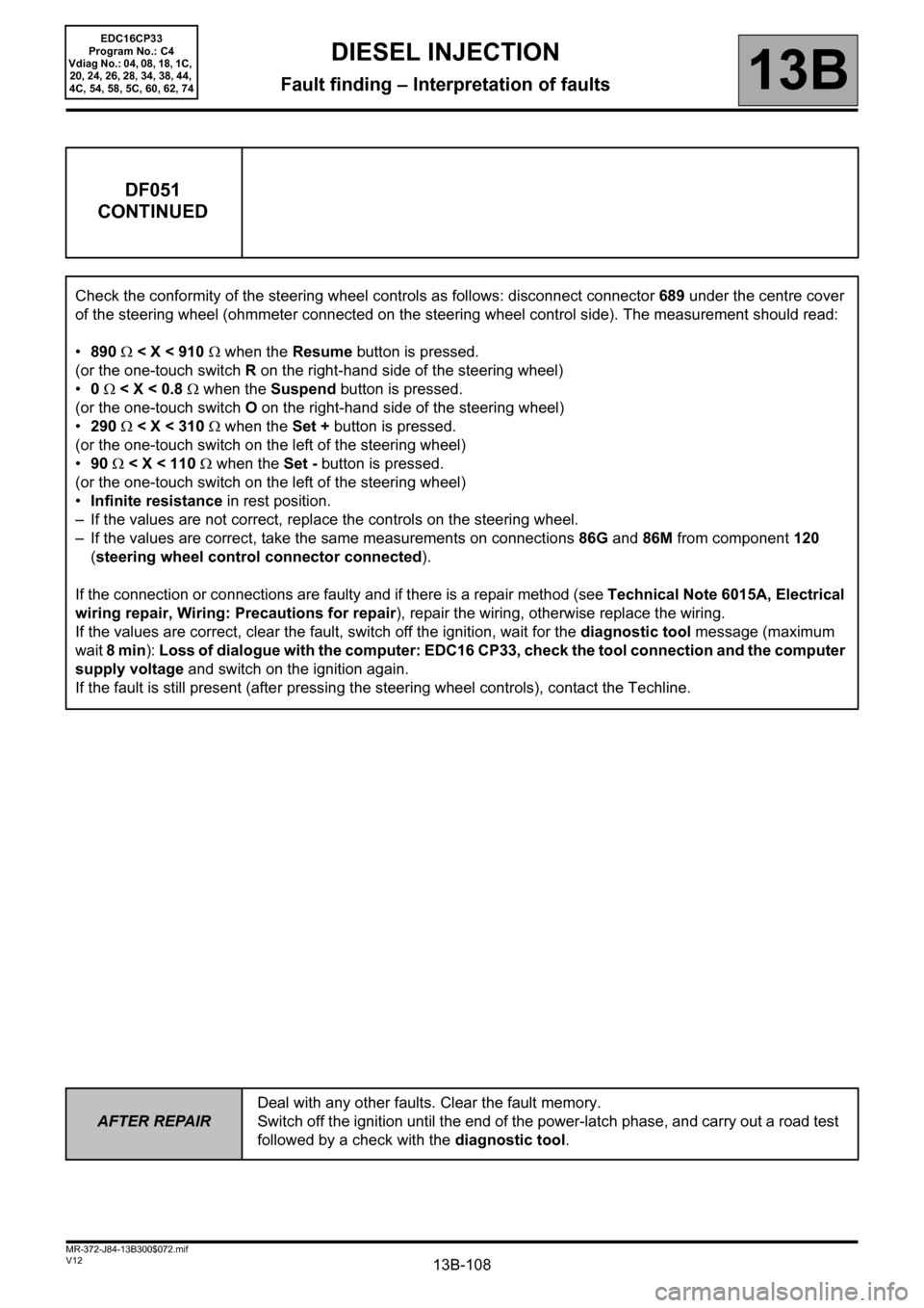
Check the conformity of the steering wheel controls as follows: disconnect connector689 under the centre cover
of the steering wheel (ohmmeter connected on the steering wheel control side). The measurement should read:
•890 Ω < X < 910 Ω when the Resume button is pressed.
(or the one-touch switch R on the right-hand side of the steering wheel)
•0 Ω < X < 0.8 Ω when the Suspend button is pressed.
(or the one-touch switch O on the right-hand side of the steering wheel)
•290 Ω < X < 310 Ω when the Set + button is pressed.
(or the one-touch switch on the left of the steering wheel)
•90 Ω < X < 110 Ω when the Set - button is pressed.
(or the one-touch switch on the left of the steering wheel)
•Infinite resistance in rest position.
– If the values are not correct, replace the controls on the steering wheel.
– If the values are correct, take the same measurements on connections86G and 86M from component120
(steering wheel control connector connected).
If the connection or connections are faulty and if there is a repair method (see Technical Note 6015A, Electrical
wiring repair, Wiring: Precautions for repair), repair the wiring, otherwise replace the wiring.
If the values are correct, clear the fault, switch off the ignition, wait for the diagnostic tool message (maximum
wait 8 min): Loss of dialogue with the computer: EDC16 CP33, check the tool connection and the computer
supply voltage and switch on the ignition again.
If the fault is still present (after pressing the steering wheel controls), contact the Techline.
Page 301 of 510
13B-301V12 MR-372-J84-13B300$101.mif
DIESEL INJECTION
Fault finding – Interpretation of statuses13B
ET415
CONTINUED 3
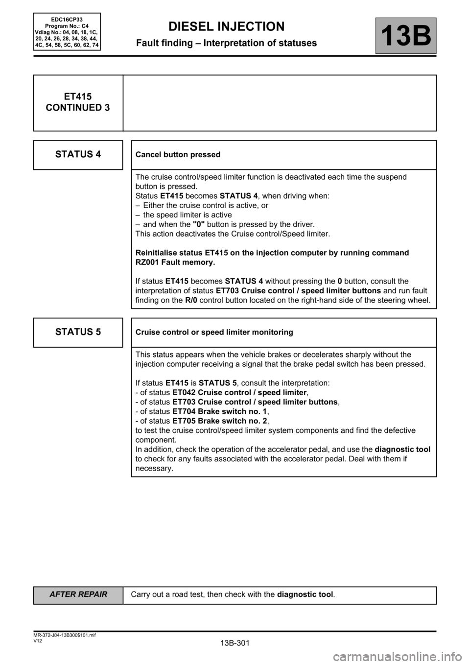
STATUS 4
Cancel button pressed
The cruise control/speed limiter function is deactivated each time the suspend
button is pressed.
Status ET415 becomes STATUS 4, when driving when:
– Either the cruise control is active, or
– the speed limiter is active
– and when the "0" button is pressed by the driver.
This action deactivates the Cruise control/Speed limiter.
Reinitialise status ET415 on the injection computer by running command
RZ001 Fault memory.
If status ET415 becomes STATUS 4 without pressing the 0 button, consult the
interpretation of status ET703 Cruise control / speed limiter buttons and run fault
finding on the R/0 control button located on the right-hand side of the steering wheel.
STATUS 5Cruise control or speed limiter monitoring
This status appears when the vehicle brakes or decelerates sharply without the
injection computer receiving a signal that the brake pedal switch has been pressed.
If status ET415 is STATUS 5, consult the interpretation:
- of status ET042 Cruise control / speed limiter,
- of status ET703 Cruise control / speed limiter buttons,
- of status ET704 Brake switch no. 1,
- of status ET705 Brake switch no. 2,
to test the cruise control/speed limiter system components and find the defective
component.
In addition, check the operation of the accelerator pedal, and use the diagnostic tool
to check for any faults associated with the accelerator pedal. Deal with them if
necessary.
AFTER REPAIRCarry out a road test, then check with the diagnostic tool.
EDC16CP33
Program No.: C4
Vdiag No.: 04, 08, 18, 1C,
20, 24, 26, 28, 34, 38, 44,
4C, 54, 58, 5C, 60, 62, 74
Page 311 of 510
13B-311V12 MR-372-J84-13B300$102.mif
13B
ET703
CONTINUED 1
Sensor electrical conformity
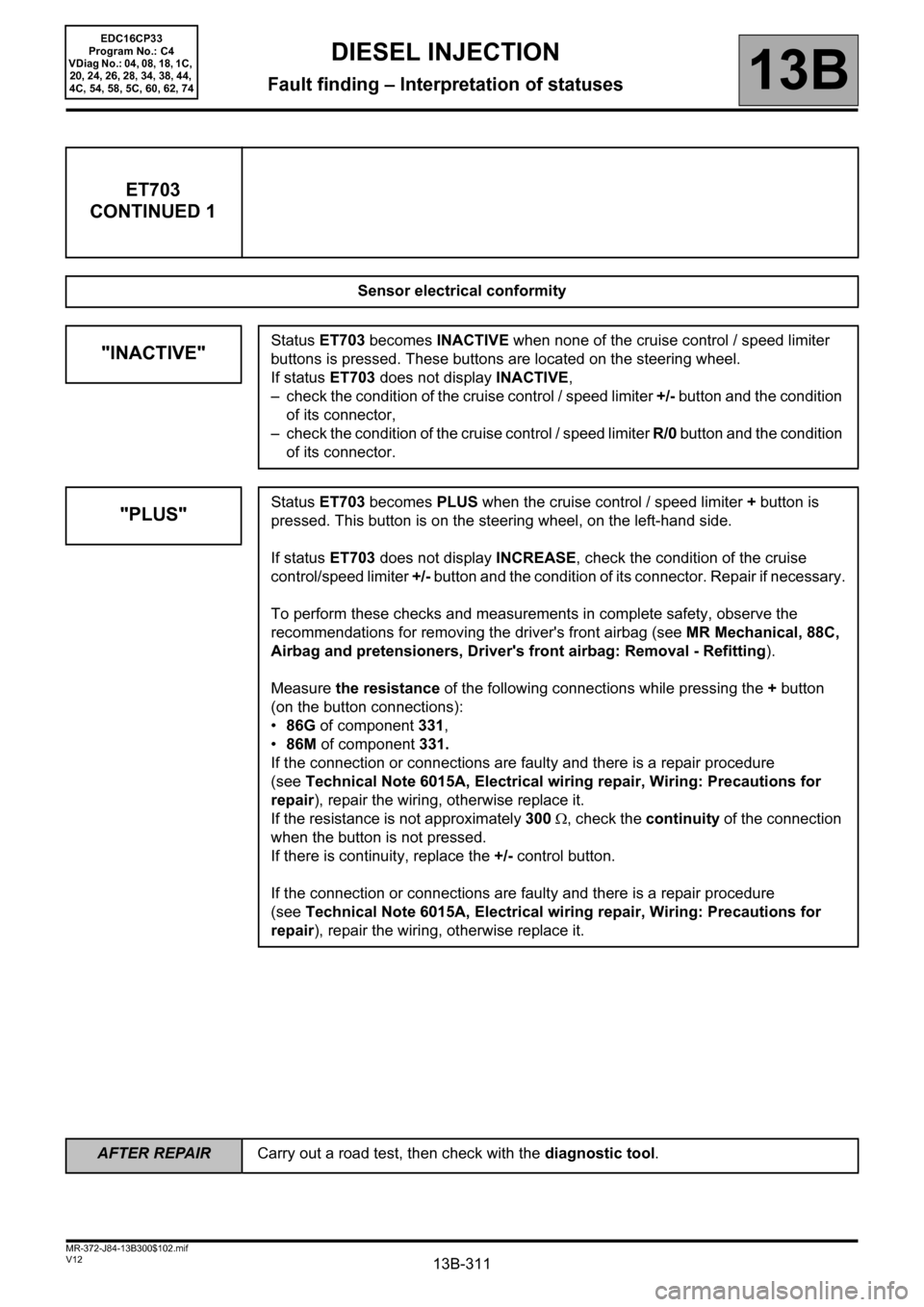
"INACTIVE"Status ET703 becomes INACTIVE when none of the cruise control / speed limiter
buttons is pressed. These buttons are located on the steering wheel.
If status ET703 does not display INACTIVE,
– check the condition of the cruise control / speed limiter +/- button and the condition
of its connector,
– check the condition of the cruise control / speed limiter R/0 button and the condition
of its connector.
"PLUS"Status ET703 becomes PLUS when the cruise control / speed limiter + button is
pressed. This button is on the steering wheel, on the left-hand side.
If status ET703 does not display INCREASE, check the condition of the cruise
control/speed limiter +/- button and the condition of its connector. Repair if necessary.
To perform these checks and measurements in complete safety, observe the
recommendations for removing the driver's front airbag (see MR Mechanical, 88C,
Airbag and pretensioners, Driver's front airbag: Removal - Refitting).
Measure the resistance of the following connections while pressing the + button
(on the button connections):
•86G of component 331,
•86M of component 331.
If the connection or connections are faulty and there is a repair procedure
(seeTechnical Note 6015A, Electrical wiring repair, Wiring: Precautions for
repair), repair the wiring, otherwise replace it.
If the resistance is not approximately 300 Ω, check the continuity of the connection
when the button is not pressed.
If there is continuity, replace the +/- control button.
If the connection or connections are faulty and there is a repair procedure
(seeTechnical Note 6015A, Electrical wiring repair, Wiring: Precautions for
repair), repair the wiring, otherwise replace it.
DIESEL INJECTION
Fault finding – Interpretation of statuses
AFTER REPAIRCarry out a road test, then check with the diagnostic tool.
EDC16CP33
Program No.: C4
VDiag No.: 04, 08, 18, 1C,
20, 24, 26, 28, 34, 38, 44,
4C, 54, 58, 5C, 60, 62, 74
Page 312 of 510
13B-312V12 MR-372-J84-13B300$102.mif
DIESEL INJECTION
Fault finding – Interpretation of statuses13B
ET703
CONTINUED 2
"MINUS"
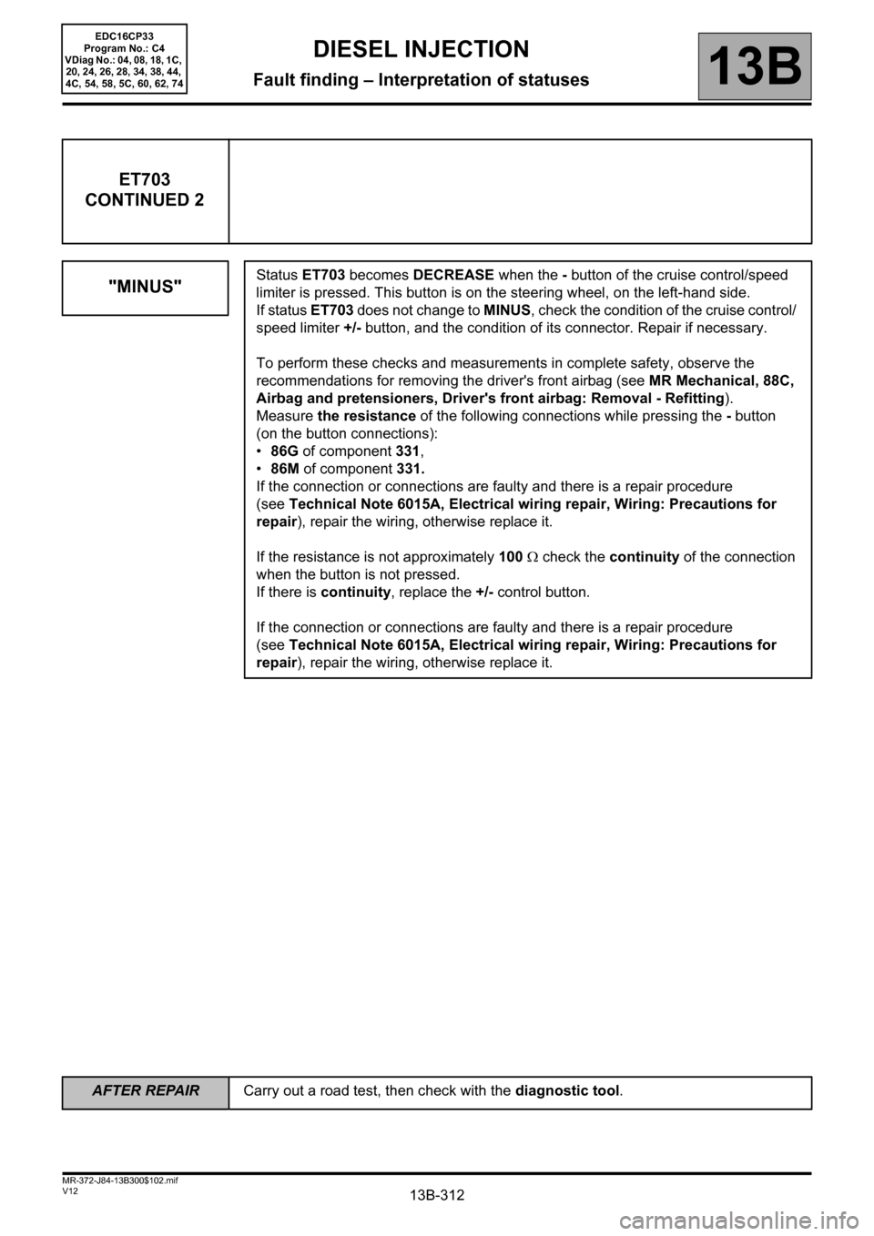
Status ET703 becomes DECREASE when the - button of the cruise control/speed
limiter is pressed. This button is on the steering wheel, on the left-hand side.
If status ET703 does not change to MINUS, check the condition of the cruise control/
speed limiter +/- button, and the condition of its connector. Repair if necessary.
To perform these checks and measurements in complete safety, observe the
recommendations for removing the driver's front airbag (see MR Mechanical, 88C,
Airbag and pretensioners, Driver's front airbag: Removal - Refitting).
Measure the resistance of the following connections while pressing the - button
(on the button connections):
•86G of component 331,
•86M of component 331.
If the connection or connections are faulty and there is a repair procedure
(seeTechnical Note 6015A, Electrical wiring repair, Wiring: Precautions for
repair), repair the wiring, otherwise replace it.
If the resistance is not approximately 100 Ω check the continuity of the connection
when the button is not pressed.
If there is continuity, replace the +/- control button.
If the connection or connections are faulty and there is a repair procedure
(seeTechnical Note 6015A, Electrical wiring repair, Wiring: Precautions for
repair), repair the wiring, otherwise replace it.
AFTER REPAIRCarry out a road test, then check with the diagnostic tool.
EDC16CP33
Program No.: C4
VDiag No.: 04, 08, 18, 1C,
20, 24, 26, 28, 34, 38, 44,
4C, 54, 58, 5C, 60, 62, 74
Page 313 of 510
13B-313V12 MR-372-J84-13B300$102.mif
DIESEL INJECTION
Fault finding – Interpretation of statuses13B
ET703
CONTINUED 3
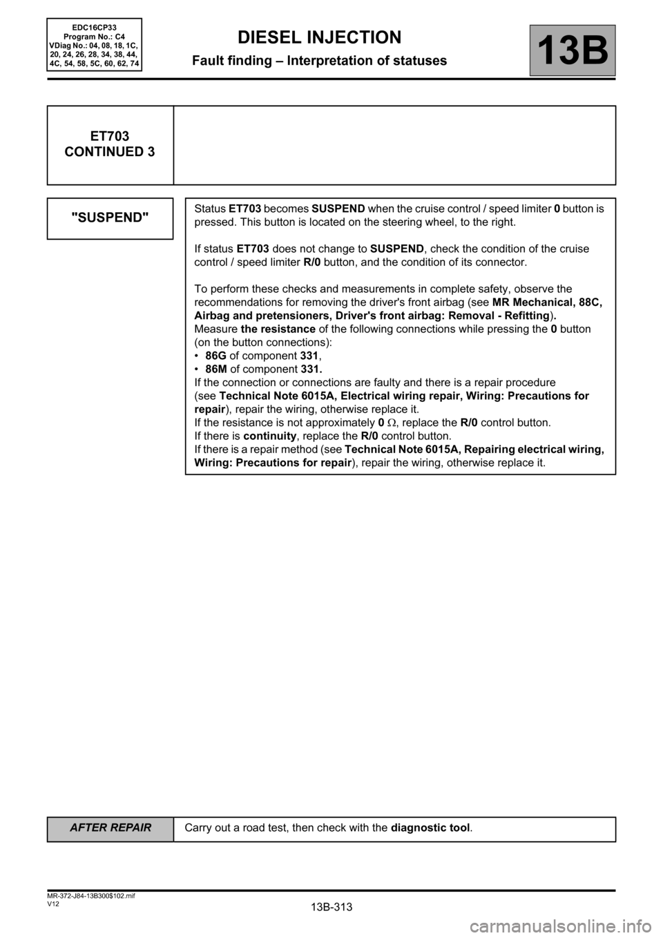
"SUSPEND"
Status ET703 becomes SUSPEND when the cruise control / speed limiter 0 button is
pressed. This button is located on the steering wheel, to the right.
If status ET703 does not change to SUSPEND, check the condition of the cruise
control / speed limiter R/0 button, and the condition of its connector.
To perform these checks and measurements in complete safety, observe the
recommendations for removing the driver's front airbag (see MR Mechanical, 88C,
Airbag and pretensioners, Driver's front airbag: Removal - Refitting).
Measure the resistance of the following connections while pressing the 0 button
(on the button connections):
•86G of component 331,
•86M of component 331.
If the connection or connections are faulty and there is a repair procedure
(seeTechnical Note 6015A, Electrical wiring repair, Wiring: Precautions for
repair), repair the wiring, otherwise replace it.
If the resistance is not approximately 0 Ω, replace the R/0 control button.
If there is continuity, replace the R/0 control button.
If there is a repair method (see Technical Note 6015A, Repairing electrical wiring,
Wiring: Precautions for repair), repair the wiring, otherwise replace it.
EDC16CP33
Program No.: C4
VDiag No.: 04, 08, 18, 1C,
20, 24, 26, 28, 34, 38, 44,
4C, 54, 58, 5C, 60, 62, 74
AFTER REPAIRCarry out a road test, then check with the diagnostic tool.
Page 314 of 510
13B-314V12 MR-372-J84-13B300$102.mif
DIESEL INJECTION
Fault finding – Interpretation of statuses13B
ET703
CONTINUED 4
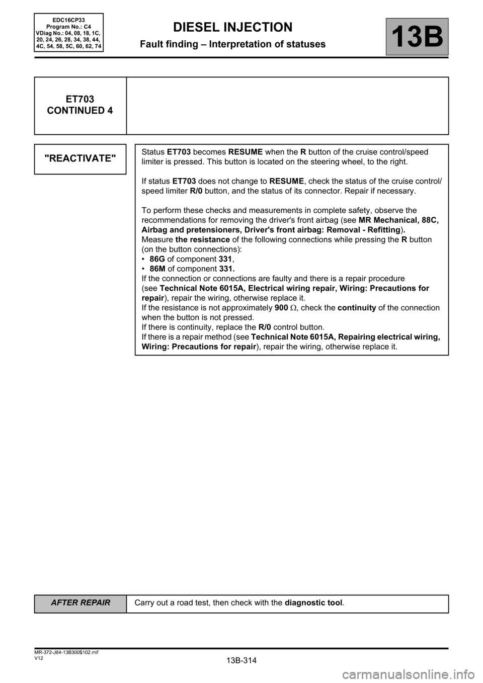
"REACTIVATE"
Status ET703 becomes RESUME when the R button of the cruise control/speed
limiter is pressed. This button is located on the steering wheel, to the right.
If status ET703 does not change to RESUME, check the status of the cruise control/
speed limiter R/0 button, and the status of its connector. Repair if necessary.
To perform these checks and measurements in complete safety, observe the
recommendations for removing the driver's front airbag (see MR Mechanical, 88C,
Airbag and pretensioners, Driver's front airbag: Removal - Refitting).
Measure the resistance of the following connections while pressing the R button
(on the button connections):
•86G of component 331,
•86M of component 331.
If the connection or connections are faulty and there is a repair procedure
(seeTechnical Note 6015A, Electrical wiring repair, Wiring: Precautions for
repair), repair the wiring, otherwise replace it.
If the resistance is not approximately 900 Ω, check the continuity of the connection
when the button is not pressed.
If there is continuity, replace the R/0 control button.
If there is a repair method (see Technical Note 6015A, Repairing electrical wiring,
Wiring: Precautions for repair), repair the wiring, otherwise replace it.
AFTER REPAIRCarry out a road test, then check with the diagnostic tool.
EDC16CP33
Program No.: C4
VDiag No.: 04, 08, 18, 1C,
20, 24, 26, 28, 34, 38, 44,
4C, 54, 58, 5C, 60, 62, 74