ESP RENAULT SCENIC 2013 J95 / 3.G Electronic Parking Brake Service Manual
[x] Cancel search | Manufacturer: RENAULT, Model Year: 2013, Model line: SCENIC, Model: RENAULT SCENIC 2013 J95 / 3.GPages: 115, PDF Size: 0.64 MB
Page 65 of 115
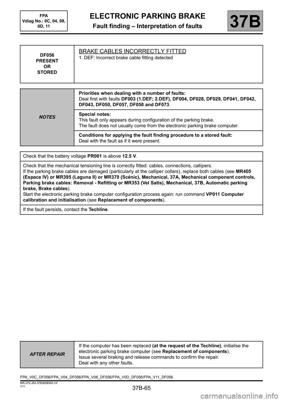
37B-65
MR-372-J84-37B000$504.mif
V11
ELECTRONIC PARKING BRAKE
Fault finding – Interpretation of faults
FPA
Vdiag No.: 0C, 04, 08,
0D, 11
37B
DF056
PRESENT
OR
STOREDBRAKE CABLES INCORRECTLY FITTED
1. DEF: Incorrect brake cable fitting detected
NOTESPriorities when dealing with a number of faults:
Deal first with faults DF003 (1.DEF; 2.DEF), DF004, DF028, DF029, DF041, DF042,
DF043, DF050, DF057, DF058 and DF073.
Special notes:
This fault only appears during configuration of the parking brake.
The fault does not usually come from the electronic parking brake computer.
Conditions for applying the fault finding procedure to a stored fault:
Deal with the fault as if it were present.
Check that the battery voltage PR001 is above 12.5 V.
Check that the mechanical tensioning line is correctly fitted: cables, connections, callipers.
If the parking brake cables are damaged (particularly at the calliper collars), replace both cables (see MR405
(Espace IV) or MR395 (Laguna II) or MR370 (Scénic), Mechanical, 37A, Mechanical component controls,
Parking brake cables: Removal - Refitting or MR353 (Vel Satis), Mechanical, 37B, Automatic parking
brake, Brake cables).
Start the electronic parking brake computer configuration process again: run command VP011 Computer
calibration and initialisation (see Replacement of components).
If the fault persists, contact the Techline.
AFTER REPAIRIf the computer has been replaced (at the request of the Techline), initialise the
electronic parking brake computer (see Replacement of components).
Issue several braking and release commands to confirm the repair.
Deal with any other faults.
FPA_V0C_DF056/FPA_V04_DF056/FPA_V08_DF056/FPA_V0D_DF056/FPA_V11_DF056
Page 68 of 115
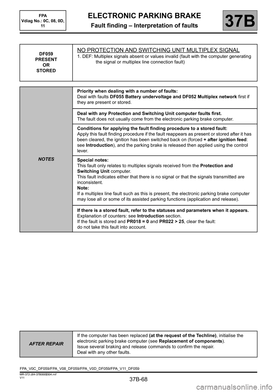
37B-68
MR-372-J84-37B000$504.mif
V11
ELECTRONIC PARKING BRAKE
Fault finding – Interpretation of faults37B
DF059
PRESENT
OR
STOREDNO PROTECTION AND SWITCHING UNIT MULTIPLEX SIGNAL
1. DEF: Multiplex signals absent or values invalid (fault with the computer generating
the signal or multiplex line connection fault)
NOTESPriority when dealing with a number of faults:
Deal with faults DF055 Battery undervoltage and DF052 Multiplex network first if
they are present or stored.
Deal with any Protection and Switching Unit computer faults first.
The fault does not usually come from the electronic parking brake computer.
Conditions for applying the fault finding procedure to a stored fault:
Apply this fault finding procedure if the fault reappears as present or stored after it has
been cleared, the ignition has been switched back on (forced + after ignition feed:
see Introduction), and the parking brake is released then applied using the control
lever.
Special notes:
This fault only relates to multiplex signals received from the Protection and
Switching Unit computer.
This fault indicates either that there is no signal or that the signals transmitted are
inconsistent.
Note:
If a multiplex line fault such as this is present, the electronic parking brake computer
may lose all or some of its assisted parking functions (application and release).
If there is a stored fault, refer to the statuses and parameters when it appears.
Explanation of counters: see Introduction section.
If the fault is stored and PR018 = 0 and PR022 > 25, clear the fault:
do not take this fault into account.
AFTER REPAIRIf the computer has been replaced (at the request of the Techline), initialise the
electronic parking brake computer (see Replacement of components).
Issue several braking and release commands to confirm the repair.
Deal with any other faults.
FPA_V0C_DF059/FPA_V08_DF059/FPA_V0D_DF059/FPA_V11_DF059
FPA
Vdiag No.: 0C, 08, 0D,
11
Page 69 of 115
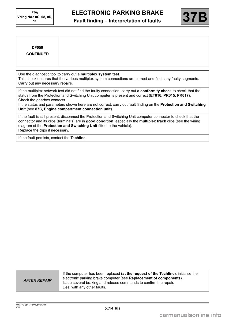
37B-69
MR-372-J84-37B000$504.mif
V11
ELECTRONIC PARKING BRAKE
Fault finding – Interpretation of faults37B
DF059
CONTINUED
Use the diagnostic tool to carry out a multiplex system test.
This check ensures that the various multiplex system connections are correct and finds any faulty segments.
Carry out any necessary repairs.
If the multiplex network test did not find the faulty connection, carry out a conformity check to check that the
status from the Protection and Switching Unit computer is present and correct (ET016, PR015, PR017).
Check the gearbox contacts.
If the status and parameters shown here are not correct, carry out fault finding on the Protection and Switching
Unit (see 87G, Engine compartment connection unit).
If the fault is still present, disconnect the Protection and Switching Unit computer connector to check that the
connector and its clips (terminals) are in good condition, especially the multiplex track clips (see the wiring
diagram of the Protection and Switching Unit fitted to the vehicle).
Replace the clips if necessary.
If the fault persists, contact the Techline.
AFTER REPAIRIf the computer has been replaced (at the request of the Techline), initialise the
electronic parking brake computer (see Replacement of components).
Issue several braking and release commands to confirm the repair.
Deal with any other faults.
FPA
Vdiag No.: 0C, 08, 0D,
11
Page 70 of 115
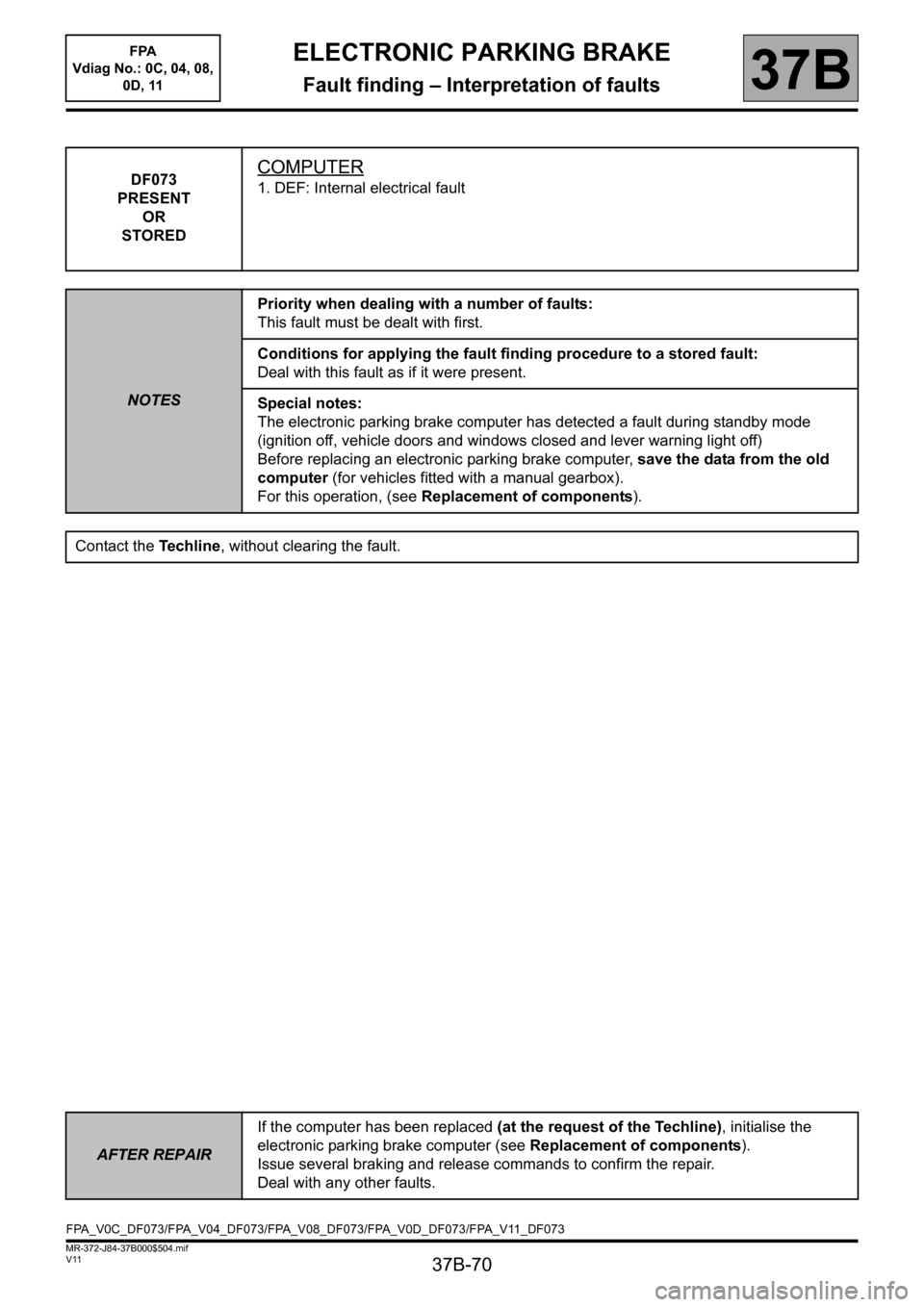
37B-70
MR-372-J84-37B000$504.mif
V11
ELECTRONIC PARKING BRAKE
Fault finding – Interpretation of faults
FPA
Vdiag No.: 0C, 04, 08,
0D, 11
37B
DF073
PRESENT
OR
STOREDCOMPUTER
1. DEF: Internal electrical fault
NOTESPriority when dealing with a number of faults:
This fault must be dealt with first.
Conditions for applying the fault finding procedure to a stored fault:
Deal with this fault as if it were present.
Special notes:
The electronic parking brake computer has detected a fault during standby mode
(ignition off, vehicle doors and windows closed and lever warning light off)
Before replacing an electronic parking brake computer, save the data from the old
computer (for vehicles fitted with a manual gearbox).
For this operation, (see Replacement of components).
Contact the Techline, without clearing the fault.
AFTER REPAIRIf the computer has been replaced (at the request of the Techline), initialise the
electronic parking brake computer (see Replacement of components).
Issue several braking and release commands to confirm the repair.
Deal with any other faults.
FPA_V0C_DF073/FPA_V04_DF073/FPA_V08_DF073/FPA_V0D_DF073/FPA_V11_DF073
Page 94 of 115
37B-94
MR-372-J84-37B000$648.mif
V11
FPA
Vdiag No.: 0C, 04, 08,
0D, 11
37B
ET001
+ AFTER IGNITION FEED
NOTESNone
This status means there is a + 12 V computer after ignition.
When the ignition is switched off, the status displays: ABSENT.
When the ignition is switched on, the status displays: PRESENT.
If the status does not operate as specified: disconnect the electronic parking brake computer connector to check
the insulation, continuity and the absence of interference resistance on the following connections:
Automatic parking brake computer connector
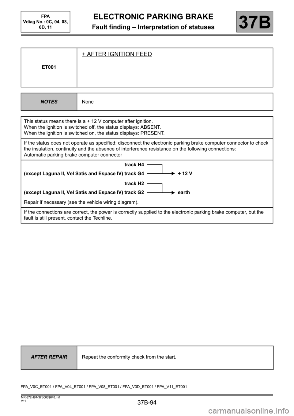
track H4
(except Laguna II, Vel Satis and Espace IV) track G4 + 12 V
track H2
(except Laguna II, Vel Satis and Espace IV) track G2 earth
Repair if necessary (see the vehicle wiring diagram).
If the connections are correct, the power is correctly supplied to the electronic parking brake computer, but the
fault is still present, contact the Techline.
AFTER REPAIRRepeat the conformity check from the start.
FPA_V0C_ET001 / FPA_V04_ET001 / FPA_V08_ET001 / FPA_V0D_ET001 / FPA_V11_ET001
ELECTRONIC PARKING BRAKE
Fault finding – Interpretation of statuses
Page 105 of 115
37B-105
MR-372-J84-37B000$936.mif
V11
ELECTRONIC PARKING BRAKE
Fault finding – Fault finding chart
FPA
Vdiag No.: 0C, 04, 08,
0D, 11
37B
ALP1 No dialogue with the computer
NOTESNone.
Try the diagnostic tool on another vehicle.
Check:
– the connection between the diagnostic tool and the diagnostic sensor (wiring in good condition),
– the connection between the diagnostic sensor and the diagnostic socket (lead in good condition),
– the engine and passenger compartment fuses.
Check for + 12 V battery on track 16, and + 12 V after ignition feed on track 1 and an earth on track 5 and on
track 4 of the diagnostic socket.
Repair if necessary.
Disconnect the automatic or electronic parking brake computer connector to check the insulation, continuity
and absence of interference resistance on the following connections:
Automatic parking brake computer connector
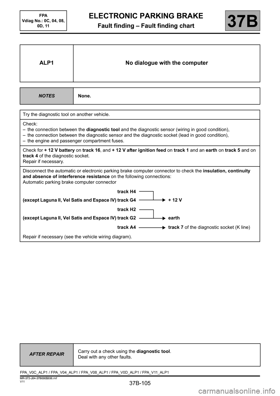
track H4
(except Laguna II, Vel Satis and Espace IV) track G4 + 12 V
track H2
(except Laguna II, Vel Satis and Espace IV) track G2 earth
track A4 track 7 of the diagnostic socket (K line)
Repair if necessary (see the vehicle wiring diagram).
AFTER REPAIRCarry out a check using the diagnostic tool.
Deal with any other faults.
FPA_V0C_ALP1 / FPA_V04_ALP1 / FPA_V08_ALP1 / FPA_V0D_ALP1 / FPA_V11_ALP1
ELECTRONIC PARKING BRAKE
Fault finding – Fault finding chart
MR-372-J84-37B000$936.mif
Page 107 of 115
37B-107
MR-372-J84-37B000$936.mif
V11
ELECTRONIC PARKING BRAKE
Fault finding – Fault finding chart
FPA
Vdiag No.: 0C, 04, 08,
0D, 11
37B
ALP2
CONTINUED 1
For a vehicle fitted with an automatic gearbox:
Check the connection and condition of the automatic gearbox multifunction switch, component code 779.
Check the connection and condition of the automatic gearbox computer, component code 119.
If the connectors are faulty and if there is a repair procedure (see Technical Note 6015A, Repairing electrical
wiring, Wiring: Precautions for repair) repair the connector(s); otherwise, replace the wiring.
Check the insulation, continuity and the absence of interference resistance of the following connections:
●5DF between components 779 and 119,
●5DG between components 779 and 119,
●5DH between components 779 and 119,
●5CF between components 779 and 119.
If the connection or connections are faulty and there is a repair procedure (see Technical Note 6015A, Electrical
wiring repair, Wiring: Precautions for repair), repair the wiring, otherwise replace it.
For a vehicle fitted with a manual gearbox:
Check the connection and condition of the reversing lights sensor, component code 1109.
Check the connection and condition of the Protection and Switching Unit, component code 1337 (Only for Scénic
II), or the UCH, component code 645 (Only for Vel Satis phase 1 and phase 2, Laguna II phase 2, Espace IV
phase 1 and phase 2).
If the connectors are faulty and if there is a repair procedure (see Technical Note 6015A, Repairing electrical
wiring, Wiring: Precautions for repair) repair the connector(s); otherwise, replace the wiring.
Check the insulation, continuity and the absence of interference resistance of the following connection:
●H66P between components 1109 and 1337 (Only for Scénic II),
●H66P between components 1109 and 645 (Only for Vel Satis phase 1 and phase 2, Laguna II phase 2,
Espace IV phase 1 and phase 2).
If the connection or connections are faulty and there is a repair procedure (see Technical Note 6015A, Electrical
wiring repair, Wiring: Precautions for repair), repair the wiring, otherwise replace it.
AFTER REPAIRCarry out a check using the diagnostic tool.
Deal with any other faults.
Page 109 of 115
37B-109
MR-372-J84-37B000$936.mif
V11
ELECTRONIC PARKING BRAKE
Fault finding – Fault finding chart
FPA
Vdiag No.: 0C, 04, 08,
0D, 11
37B
ALP3 Assisted release too early or too late
NOTESOnly consult this customer complaint after a full check using the diagnostic tool
(no present or stored faults).
(see the wiring diagrams technical note for the vehicle concerned).
Assisted release may be activated too late if a trailer is attached to the vehicle.
Test assisted release without the trailer.
Test the braking system:
Look for any areas where the brake pads may be sticking (due to ice, salt, etc.).
Check that the brake piston is operating correctly.
Repair if necessary.
Check the clutch sensor positioning:
●Espace IV and Vel Satis
Check the insulation, continuity and the absence of interference resistance on the following connections:
– connection code 150K,
– connection code 150L,
– connection code 26X.
Between the electronic parking brake computer, component code 1217 and the clutch position sensor,
component code 1057.
If there is a repair procedure (see Technical Note 6015A, Repairing electrical wiring, Wiring: Precautions for
repair), repair the wiring, otherwise replace the wiring.
Reposition it, if necessary.
Replace the clutch sensor if necessary (see MR405 (Espace IV) or MR395 (Laguna II) or MR370 (Scénic),
Mechanical, 37A, Mechanical component controls, Clutch pedal position sensor: Removal - Refitting or
MR353 (Vel Satis ph 1), Mechanical, 37A, Mechanical component controls, Clutch pedal or MR402 (Vel
Satis ph 2), Mechanical, 37A, Mechanical component controls, Clutch pedal switch: Removal - Refitting).
●Laguna II and Scénic II
Check the insulation, continuity and the absence of interference resistance on the following connections:
– connection code 150Q,
– connection code 150L.
Between the electronic parking brake computer, component code 1217 and the clutch pedal sensor,
component code 675 (see section 87B, UCH, Door switch).
1. Laguna II:
Check the continuity and absence of interference resistance on the following connection:
– connection code 86D
Between the injection computer, component code 120 and the clutch pedal switch, component code 675.
AFTER REPAIRCarry out a check using the diagnostic tool.
Deal with any other faults.
FPA_V0C_ALP3 / FPA_V04_ALP3 / FPA_V08_ALP3 / FPA_V0D_ALP3 / FPA_V11_ALP3
Page 110 of 115
37B-110
MR-372-J84-37B000$936.mif
V11
ELECTRONIC PARKING BRAKE
Fault finding – Fault finding chart
FPA
Vdiag No.: 0C, 04, 08,
0D, 11
37B
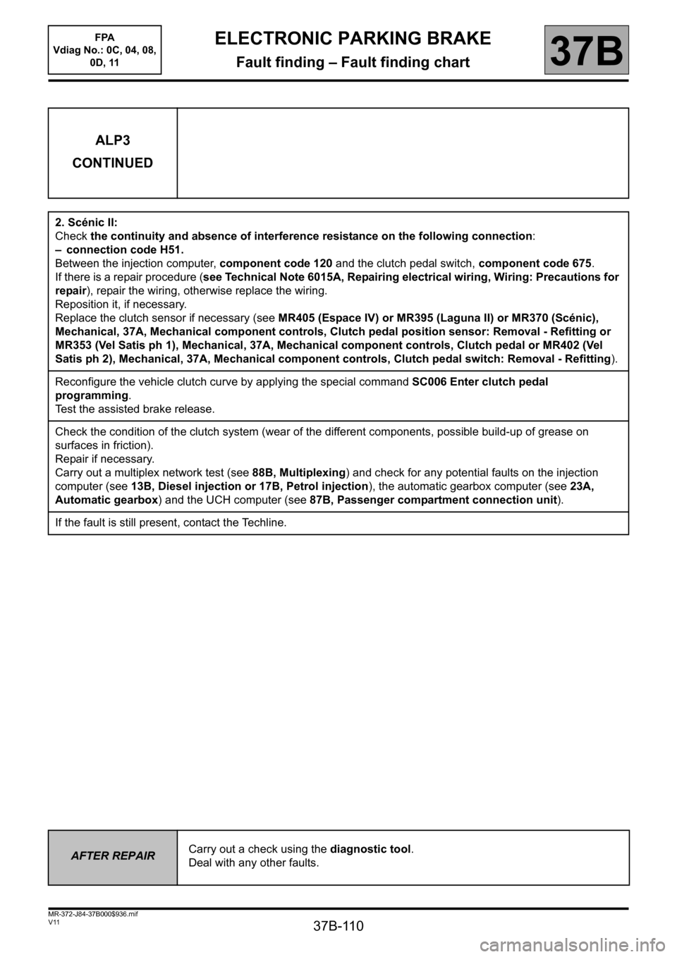
ALP3
CONTINUED
2. Scénic II:
Check the continuity and absence of interference resistance on the following connection:
– connection code H51.
Between the injection computer, component code 120 and the clutch pedal switch, component code 675.
If there is a repair procedure (see Technical Note 6015A, Repairing electrical wiring, Wiring: Precautions for
repair), repair the wiring, otherwise replace the wiring.
Reposition it, if necessary.
Replace the clutch sensor if necessary (see MR405 (Espace IV) or MR395 (Laguna II) or MR370 (Scénic),
Mechanical, 37A, Mechanical component controls, Clutch pedal position sensor: Removal - Refitting or
MR353 (Vel Satis ph 1), Mechanical, 37A, Mechanical component controls, Clutch pedal or MR402 (Vel
Satis ph 2), Mechanical, 37A, Mechanical component controls, Clutch pedal switch: Removal - Refitting).
Reconfigure the vehicle clutch curve by applying the special command SC006 Enter clutch pedal
programming.
Test the assisted brake release.
Check the condition of the clutch system (wear of the different components, possible build-up of grease on
surfaces in friction).
Repair if necessary.
Carry out a multiplex network test (see 88B, Multiplexing) and check for any potential faults on the injection
computer (see 13B, Diesel injection or 17B, Petrol injection), the automatic gearbox computer (see 23A,
Automatic gearbox) and the UCH computer (see 87B, Passenger compartment connection unit).
If the fault is still present, contact the Techline.
AFTER REPAIRCarry out a check using the diagnostic tool.
Deal with any other faults.