Df047 RENAULT SCENIC 2013 J95 / 3.G Electronic Parking Brake Workshop Manual
[x] Cancel search | Manufacturer: RENAULT, Model Year: 2013, Model line: SCENIC, Model: RENAULT SCENIC 2013 J95 / 3.GPages: 115, PDF Size: 0.64 MB
Page 17 of 115
37B-17
MR-372-J84-37B000$432.mif
V11
37B
ELECTRONIC PARKING BRAKE
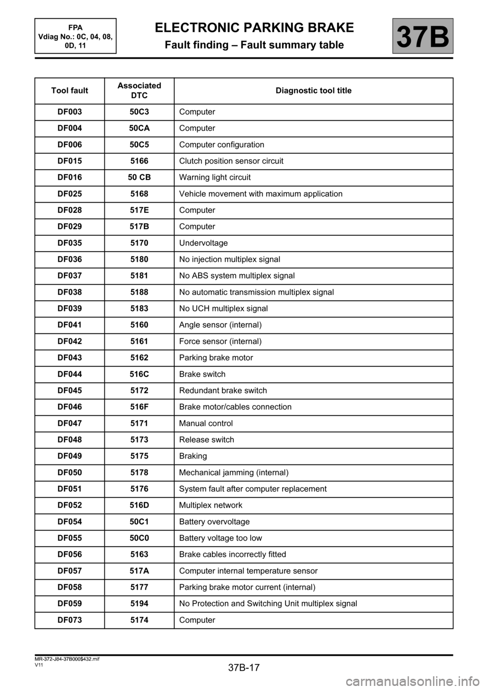
Fault finding – Fault summary table
Tool faultAssociated
DTCDiagnostic tool title
DF003 50C3Computer
DF004 50CAComputer
DF006 50C5Computer configuration
DF015 5166Clutch position sensor circuit
DF016 50 CBWarning light circuit
DF025 5168Vehicle movement with maximum application
DF028 517EComputer
DF029 517BComputer
DF035 5170Undervoltage
DF036 5180No injection multiplex signal
DF037 5181No ABS system multiplex signal
DF038 5188No automatic transmission multiplex signal
DF039 5183No UCH multiplex signal
DF041 5160Angle sensor (internal)
DF042 5161Force sensor (internal)
DF043 5162Parking brake motor
DF044 516CBrake switch
DF045 5172Redundant brake switch
DF046 516FBrake motor/cables connection
DF047 5171Manual control
DF048 5173Release switch
DF049 5175Braking
DF050 5178Mechanical jamming (internal)
DF051 5176System fault after computer replacement
DF052 516DMultiplex network
DF054 50C1Battery overvoltage
DF055 50C0Battery voltage too low
DF056 5163Brake cables incorrectly fitted
DF057 517AComputer internal temperature sensor
DF058 5177Parking brake motor current (internal)
DF059 5194No Protection and Switching Unit multiplex signal
DF073 5174Computer
FPA
Vdiag No.: 0C, 04, 08,
0D, 11
MR-372-J84-37B000$432.mif
Page 44 of 115
37B-44
MR-372-J84-37B000$504.mif
V11
ELECTRONIC PARKING BRAKE
Fault finding – Interpretation of faults
FPA
Vdiag No.: 0C, 04, 08,
0D, 11
37B
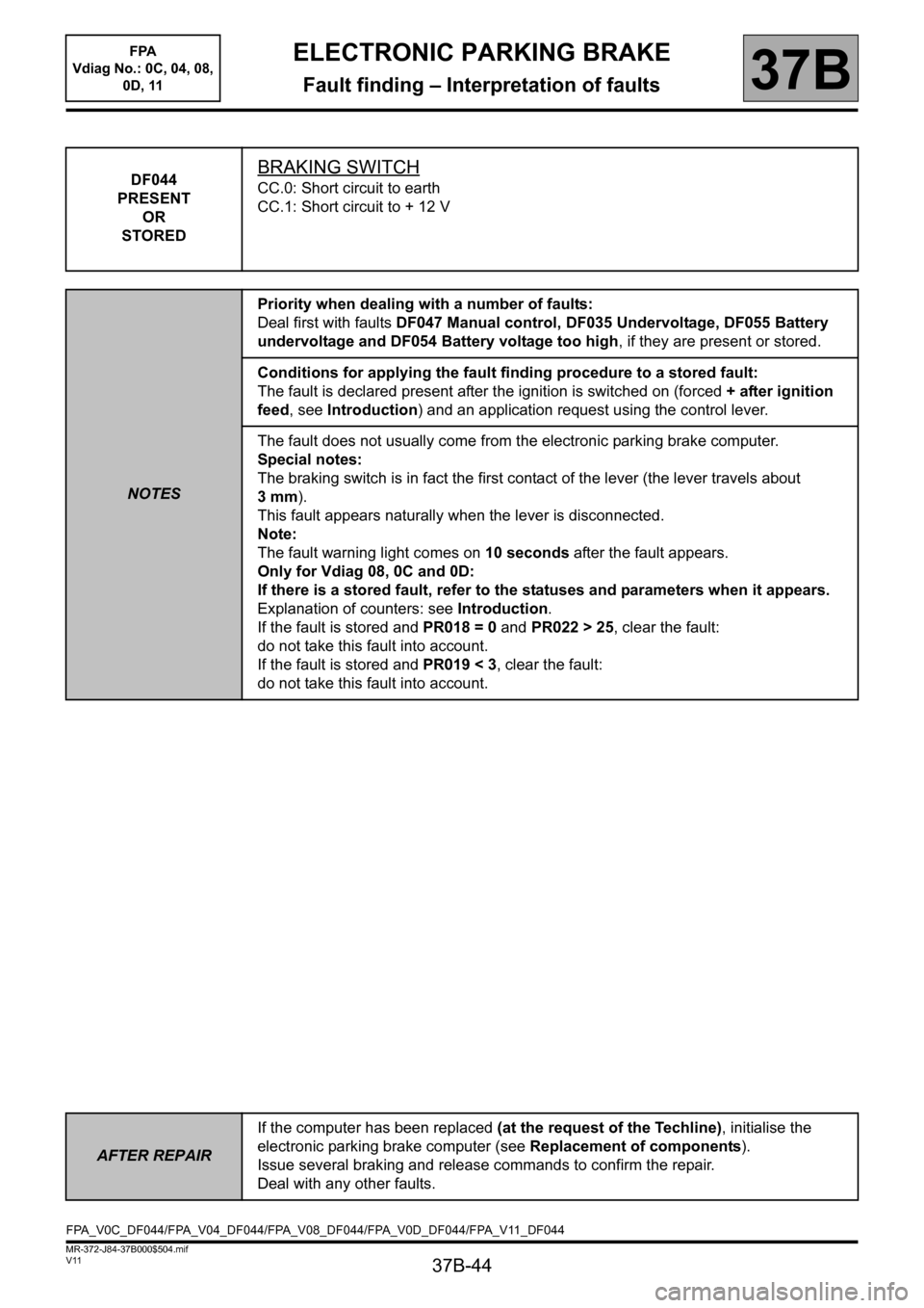
DF044
PRESENT
OR
STOREDBRAKING SWITCH
CC.0: Short circuit to earth
CC.1: Short circuit to + 12 V
NOTESPriority when dealing with a number of faults:
Deal first with faults DF047 Manual control, DF035 Undervoltage, DF055 Battery
undervoltage and DF054 Battery voltage too high, if they are present or stored.
Conditions for applying the fault finding procedure to a stored fault:
The fault is declared present after the ignition is switched on (forced + after ignition
feed, see Introduction) and an application request using the control lever.
The fault does not usually come from the electronic parking brake computer.
Special notes:
The braking switch is in fact the first contact of the lever (the lever travels about
3mm).
This fault appears naturally when the lever is disconnected.
Note:
The fault warning light comes on 10 seconds after the fault appears.
Only for Vdiag 08, 0C and 0D:
If there is a stored fault, refer to the statuses and parameters when it appears.
Explanation of counters: see Introduction.
If the fault is stored and PR018 = 0 and PR022 > 25, clear the fault:
do not take this fault into account.
If the fault is stored and PR019 < 3, clear the fault:
do not take this fault into account.
AFTER REPAIRIf the computer has been replaced (at the request of the Techline), initialise the
electronic parking brake computer (see Replacement of components).
Issue several braking and release commands to confirm the repair.
Deal with any other faults.
FPA_V0C_DF044/FPA_V04_DF044/FPA_V08_DF044/FPA_V0D_DF044/FPA_V11_DF044
Page 47 of 115
37B-47
MR-372-J84-37B000$504.mif
V11
ELECTRONIC PARKING BRAKE
Fault finding – Interpretation of faults
FPA
Vdiag No.: 0C, 04, 08,
0D, 11
37B
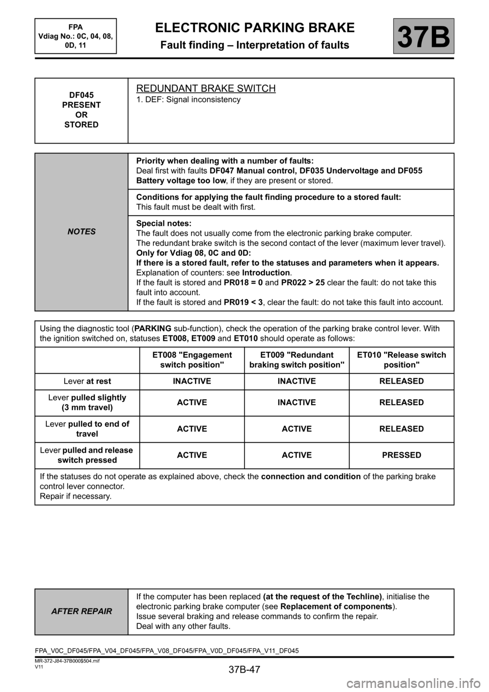
DF045
PRESENT
OR
STOREDREDUNDANT BRAKE SWITCH
1. DEF: Signal inconsistency
NOTESPriority when dealing with a number of faults:
Deal first with faults DF047 Manual control, DF035 Undervoltage and DF055
Battery voltage too low, if they are present or stored.
Conditions for applying the fault finding procedure to a stored fault:
This fault must be dealt with first.
Special notes:
The fault does not usually come from the electronic parking brake computer.
The redundant brake switch is the second contact of the lever (maximum lever travel).
Only for Vdiag 08, 0C and 0D:
If there is a stored fault, refer to the statuses and parameters when it appears.
Explanation of counters: see Introduction.
If the fault is stored and PR018 = 0 and PR022 > 25 clear the fault: do not take this
fault into account.
If the fault is stored and PR019 < 3, clear the fault: do not take this fault into account.
Using the diagnostic tool (PARKING sub-function), check the operation of the parking brake control lever. With
the ignition switched on, statuses ET008, ET009 and ET010 should operate as follows:
ET008 "Engagement
switch position"ET009 "Redundant
braking switch position"ET010 "Release switch
position"
Lever at rest INACTIVE INACTIVE RELEASED
Lever pulled slightly
(3 mm travel)ACTIVE INACTIVE RELEASED
Lever pulled to end of
travelACTIVE ACTIVE RELEASED
Lever pulled and release
switch pressedACTIVE ACTIVE PRESSED
If the statuses do not operate as explained above, check the connection and condition of the parking brake
control lever connector.
Repair if necessary.
AFTER REPAIRIf the computer has been replaced (at the request of the Techline), initialise the
electronic parking brake computer (see Replacement of components).
Issue several braking and release commands to confirm the repair.
Deal with any other faults.
FPA_V0C_DF045/FPA_V04_DF045/FPA_V08_DF045/FPA_V0D_DF045/FPA_V11_DF045
Page 50 of 115
37B-50
MR-372-J84-37B000$504.mif
V11
ELECTRONIC PARKING BRAKE
Fault finding – Interpretation of faults
FPA
Vdiag No.: 0C, 04, 08,
0D, 11
37B
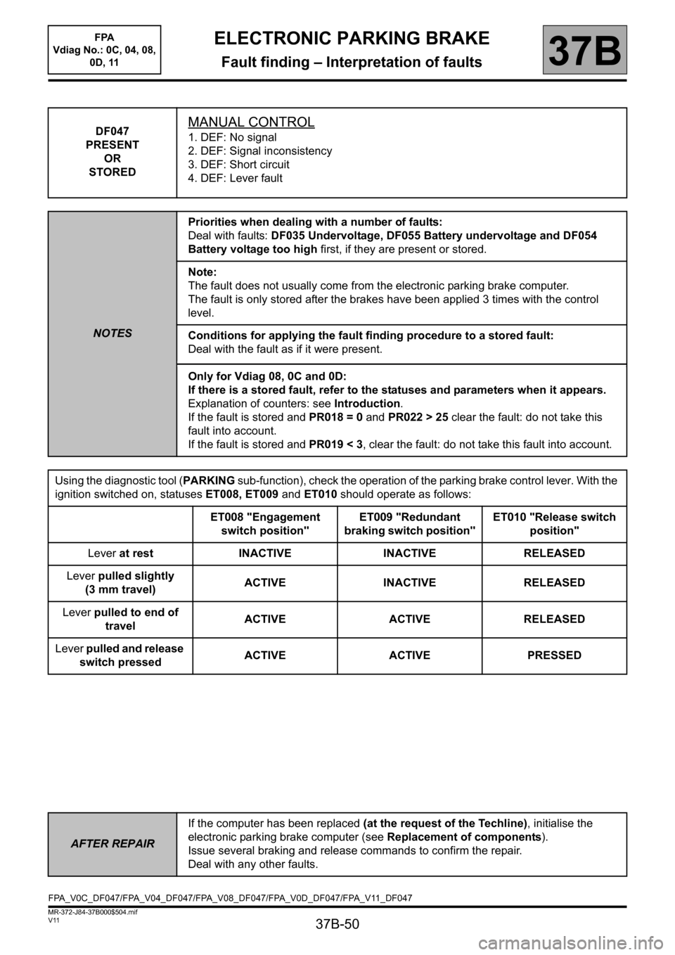
DF047
PRESENT
OR
STOREDMANUAL CONTROL
1. DEF: No signal
2. DEF: Signal inconsistency
3. DEF: Short circuit
4. DEF: Lever fault
NOTESPriorities when dealing with a number of faults:
Deal with faults: DF035 Undervoltage, DF055 Battery undervoltage and DF054
Battery voltage too high first, if they are present or stored.
Note:
The fault does not usually come from the electronic parking brake computer.
The fault is only stored after the brakes have been applied 3 times with the control
level.
Conditions for applying the fault finding procedure to a stored fault:
Deal with the fault as if it were present.
Only for Vdiag 08, 0C and 0D:
If there is a stored fault, refer to the statuses and parameters when it appears.
Explanation of counters: see Introduction.
If the fault is stored and PR018 = 0 and PR022 > 25 clear the fault: do not take this
fault into account.
If the fault is stored and PR019 < 3, clear the fault: do not take this fault into account.
Using the diagnostic tool (PARKING sub-function), check the operation of the parking brake control lever. With the
ignition switched on, statuses ET008, ET009 and ET010 should operate as follows:
ET008 "Engagement
switch position"ET009 "Redundant
braking switch position"ET010 "Release switch
position"
Lever at rest INACTIVE INACTIVE RELEASED
Lever pulled slightly
(3 mm travel)ACTIVE INACTIVE RELEASED
Lever pulled to end of
travelACTIVE ACTIVE RELEASED
Lever pulled and release
switch pressedACTIVE ACTIVE PRESSED
AFTER REPAIRIf the computer has been replaced (at the request of the Techline), initialise the
electronic parking brake computer (see Replacement of components).
Issue several braking and release commands to confirm the repair.
Deal with any other faults.
FPA_V0C_DF047/FPA_V04_DF047/FPA_V08_DF047/FPA_V0D_DF047/FPA_V11_DF047
Page 51 of 115
37B-51
MR-372-J84-37B000$504.mif
V11
ELECTRONIC PARKING BRAKE
Fault finding – Interpretation of faults
FPA
Vdiag No.: 0C, 04, 08,
0D, 11
37B
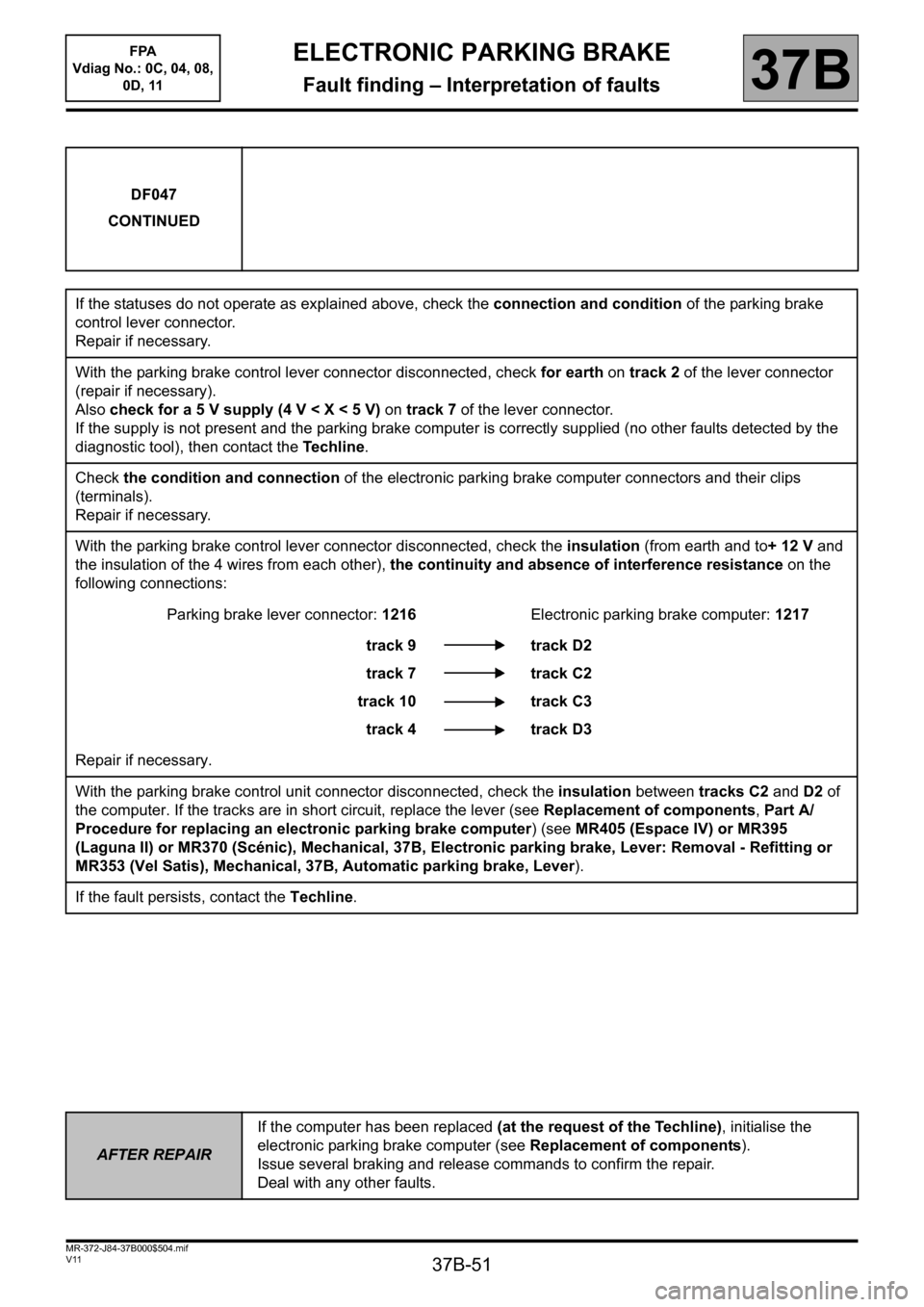
DF047
CONTINUED
If the statuses do not operate as explained above, check the connection and condition of the parking brake
control lever connector.
Repair if necessary.
With the parking brake control lever connector disconnected, check for earth on track 2 of the lever connector
(repair if necessary).
Also check for a 5 V supply (4 V < X < 5 V) on track 7 of the lever connector.
If the supply is not present and the parking brake computer is correctly supplied (no other faults detected by the
diagnostic tool), then contact the Te c h l i n e.
Check the condition and connection of the electronic parking brake computer connectors and their clips
(terminals).
Repair if necessary.
With the parking brake control lever connector disconnected, check the insulation (from earth and to+ 12 V and
the insulation of the 4 wires from each other), the continuity and absence of interference resistance on the
following connections:
Parking brake lever connector: 1216Electronic parking brake computer: 1217
track 9
track 7
track 10
track 4track D2
track C2
track C3
track D3
Repair if necessary.
With the parking brake control unit connector disconnected, check the insulation between tracks C2 and D2 of
the computer. If the tracks are in short circuit, replace the lever (see Replacement of components, Part A/
Procedure for replacing an electronic parking brake computer) (see MR405 (Espace IV) or MR395
(Laguna II) or MR370 (Scénic), Mechanical, 37B, Electronic parking brake, Lever: Removal - Refitting or
MR353 (Vel Satis), Mechanical, 37B, Automatic parking brake, Lever).
If the fault persists, contact the Techline.
AFTER REPAIRIf the computer has been replaced (at the request of the Techline), initialise the
electronic parking brake computer (see Replacement of components).
Issue several braking and release commands to confirm the repair.
Deal with any other faults.
Page 52 of 115
37B-52
MR-372-J84-37B000$504.mif
V11
ELECTRONIC PARKING BRAKE
Fault finding – Interpretation of faults
FPA
Vdiag No.: 0C, 04, 08,
0D, 11
37B
DF048
PRESENT
OR
STOREDRELEASE SWITCH
1. DEF: Signal inconsistency
NOTESPriority when dealing with a number of faults:
Deal first with faults DF003, DF004, DF028, DF029, DF035, DF041, DF042, DF043,
DF047, DF050, DF054, DF055, DF057, DF058 and DF073 if they are present or
stored.
Conditions for applying the fault finding procedure to a stored fault:
The fault is declared present after the ignition is switched on (forced + after ignition
feed, see Introduction) and a brake release request using the control lever.
Special notes:
The fault does not usually come from the electronic parking brake computer.
8 applications (in 2 seconds) using the control lever without pressing the release
switch causes the fault to appear as present.
Only for Vdiag 08, 0C and 0D:
If there is a stored fault, refer to the statuses and parameters when it appears.
Explanation of counters: see Introduction.
If the fault is stored and PR018 = 0 and PR022 > 25 clear the fault: do not take this
fault into account.
If the fault is stored and PR019 < 3, clear the fault: do not take this fault into account.
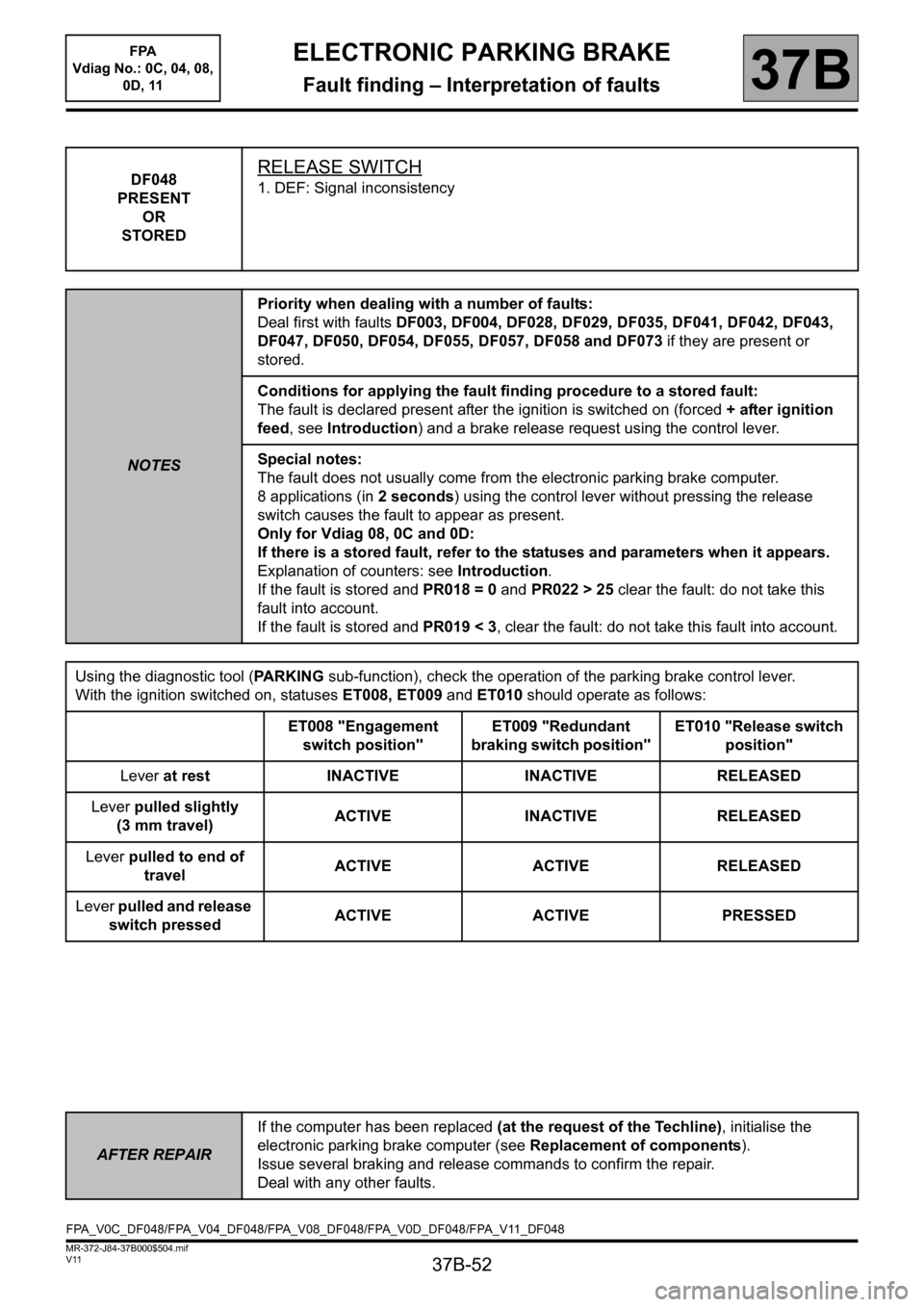
Using the diagnostic tool (PARKING sub-function), check the operation of the parking brake control lever.
With the ignition switched on, statuses ET008, ET009 and ET010 should operate as follows:
ET008 "Engagement
switch position"ET009 "Redundant
braking switch position"ET010 "Release switch
position"
Lever at rest INACTIVE INACTIVE RELEASED
Lever pulled slightly
(3 mm travel)ACTIVE INACTIVE RELEASED
Lever pulled to end of
travelACTIVE ACTIVE RELEASED
Lever pulled and release
switch pressedACTIVE ACTIVE PRESSED
AFTER REPAIRIf the computer has been replaced (at the request of the Techline), initialise the
electronic parking brake computer (see Replacement of components).
Issue several braking and release commands to confirm the repair.
Deal with any other faults.
FPA_V0C_DF048/FPA_V04_DF048/FPA_V08_DF048/FPA_V0D_DF048/FPA_V11_DF048
Page 95 of 115
37B-95
MR-372-J84-37B000$648.mif
V11
ELECTRONIC PARKING BRAKE
Fault finding – Interpretation of statuses
FPA
Vdiag No.: 0C, 04, 08,
0D, 11
37B
ET008
ET009
ET010
MANUAL CONTROL: BRAKE APPLICATION SWITCH
REDUNDANT BRAKE APPLICATION SWITCH POSITION
MANUAL CONTROL: BRAKE RELEASING SWITCH
NOTESNone
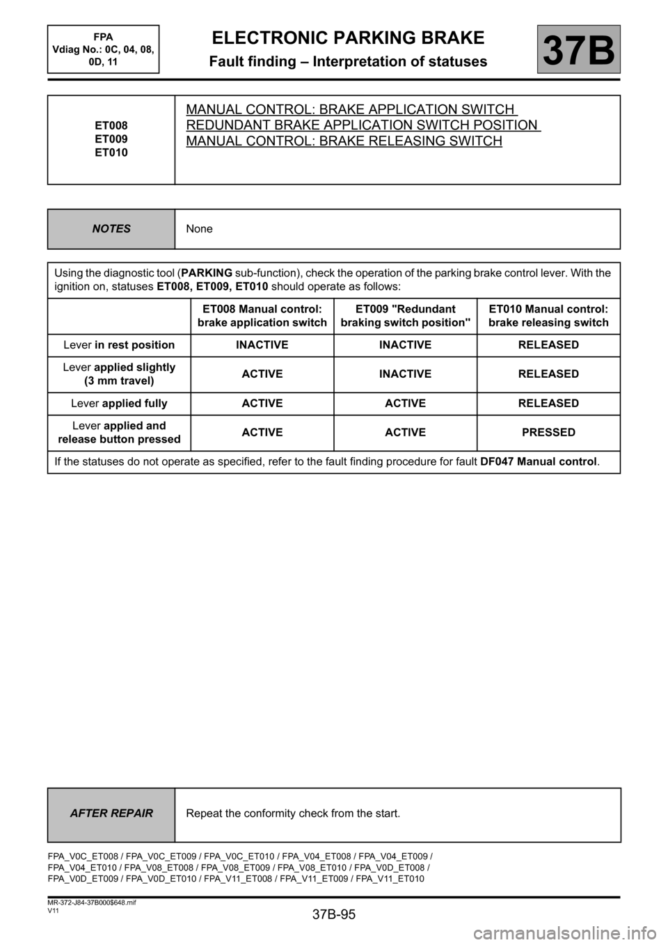
Using the diagnostic tool (PARKING sub-function), check the operation of the parking brake control lever. With the
ignition on, statuses ET008, ET009, ET010 should operate as follows:
ET008 Manual control:
brake application switchET009 "Redundant
braking switch position"ET010 Manual control:
brake releasing switch
Lever in rest position INACTIVE INACTIVE RELEASED
Lever applied slightly
(3 mm travel)ACTIVE INACTIVE RELEASED
Lever applied fully ACTIVE ACTIVE RELEASED
Lever applied and
release button pressedACTIVE ACTIVE PRESSED
If the statuses do not operate as specified, refer to the fault finding procedure for fault DF047 Manual control.
AFTER REPAIRRepeat the conformity check from the start.
FPA_V0C_ET008 / FPA_V0C_ET009 / FPA_V0C_ET010 / FPA_V04_ET008 / FPA_V04_ET009 /
FPA_V04_ET010 / FPA_V08_ET008 / FPA_V08_ET009 / FPA_V08_ET010 / FPA_V0D_ET008 /
FPA_V0D_ET009 / FPA_V0D_ET010 / FPA_V11_ET008 / FPA_V11_ET009 / FPA_V11_ET010