ESP RENAULT SCENIC 2014 J95 / 3.G Petrol Injection - Sagem3000 Repair Manual
[x] Cancel search | Manufacturer: RENAULT, Model Year: 2014, Model line: SCENIC, Model: RENAULT SCENIC 2014 J95 / 3.GPages: 181
Page 86 of 181
PETROL INJECTION
Fault finding – Interpretation of faults17B
17B - 86V12 MR-372-J84-17B000$405.mif
SAGEM 3000
Program No.: A7
Vdiag No.: 44, 48
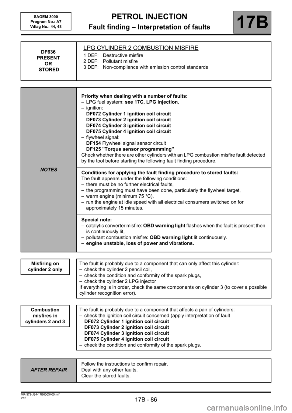
DF636
PRESENT
OR
STOREDLPG CYLINDER 2 COMBUSTION MISFIRE
1 DEF: Destructive misfire
2 DEF: Pollutant misfire
3 DEF: Non-compliance with emission control standards
NOTESPriority when dealing with a number of faults:
– LPG fuel system: see 17C, LPG injection,
– ignition:
DF072 Cylinder 1 ignition coil circuit
DF073 Cylinder 2 ignition coil circuit
DF074 Cylinder 3 ignition coil circuit
DF075 Cylinder 4 ignition coil circuit
– flywheel signal:
DF154 Flywheel signal sensor circuit
DF125 "Torque sensor programming"
Check whether there are other cylinders with an LPG combustion misfire fault detected
by the tool before starting the following fault finding procedure.
Conditions for applying the fault finding procedure to stored faults:
The fault appears under the following conditions:
– there must be no further electrical faults,
– the programming must have been done, particularly the flywheel target,
– warm engine (minimum 75 °C),
– run the engine at idle speed with all electrical consumers switched on for
approximately 15 minutes.
Special note:
– catalytic converter misfire: OBD warning light flashes when the fault is present then
is continuously lit,
– pollutant combustion misfire: OBD warning light lit continuously.
– engine unstable, loss of power and vibrations.
Misfiring on
cylinder 2 only
The fault is probably due to a component that can only affect this cylinder:
– check the cylinder 2 pencil coil,
– check the condition and conformity of the spark plugs,
– check the cylinder 2 LPG injector
If everything is in order, check the same components on cylinder 3 (to cover a possible
cylinder recognition error).
The fault is probably due to a component that affects a pair of cylinders:
– check the ignition coil circuit concerned (apply interpretation of fault
DF072 Cylinder 1 ignition coil circuit
DF073 Cylinder 2 ignition coil circuit
DF074 Cylinder 3 ignition coil circuit
DF075 Cylinder 4 ignition coil circuit
– check the condition and conformity of the spark plugs.
Combustion
misfires in
cylinders 2 and 3
AFTER REPAIRFollow the instructions to confirm repair.
Deal with any other faults.
Clear the stored faults.
Page 87 of 181
PETROL INJECTION
Fault finding – Interpretation of faults17B
17B - 87V12 MR-372-J84-17B000$405.mif
SAGEM 3000
Program No.: A7
Vdiag No.: 44, 48
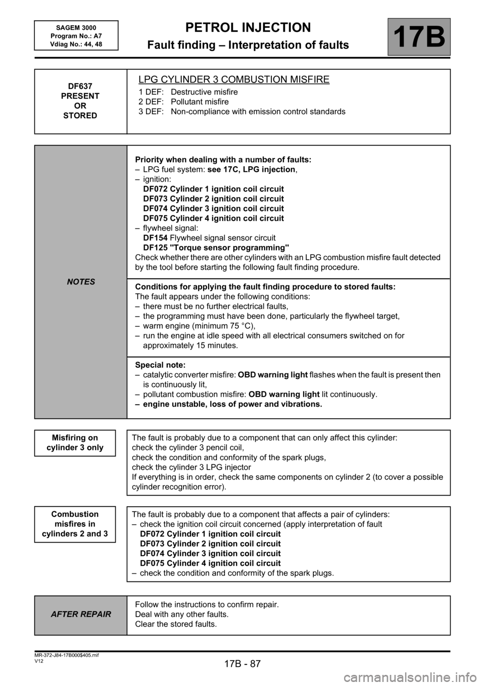
DF637
PRESENT
OR
STOREDLPG CYLINDER 3 COMBUSTION MISFIRE
1 DEF: Destructive misfire
2 DEF: Pollutant misfire
3 DEF: Non-compliance with emission control standards
NOTESPriority when dealing with a number of faults:
– LPG fuel system: see 17C, LPG injection,
– ignition:
DF072 Cylinder 1 ignition coil circuit
DF073 Cylinder 2 ignition coil circuit
DF074 Cylinder 3 ignition coil circuit
DF075 Cylinder 4 ignition coil circuit
– flywheel signal:
DF154 Flywheel signal sensor circuit
DF125 "Torque sensor programming"
Check whether there are other cylinders with an LPG combustion misfire fault detected
by the tool before starting the following fault finding procedure.
Conditions for applying the fault finding procedure to stored faults:
The fault appears under the following conditions:
– there must be no further electrical faults,
– the programming must have been done, particularly the flywheel target,
– warm engine (minimum 75 °C),
– run the engine at idle speed with all electrical consumers switched on for
approximately 15 minutes.
Special note:
– catalytic converter misfire: OBD warning light flashes when the fault is present then
is continuously lit,
– pollutant combustion misfire: OBD warning light lit continuously.
– engine unstable, loss of power and vibrations.
Misfiring on
cylinder 3 only
The fault is probably due to a component that can only affect this cylinder:
check the cylinder 3 pencil coil,
check the condition and conformity of the spark plugs,
check the cylinder 3 LPG injector
If everything is in order, check the same components on cylinder 2 (to cover a possible
cylinder recognition error).
The fault is probably due to a component that affects a pair of cylinders:
– check the ignition coil circuit concerned (apply interpretation of fault
DF072 Cylinder 1 ignition coil circuit
DF073 Cylinder 2 ignition coil circuit
DF074 Cylinder 3 ignition coil circuit
DF075 Cylinder 4 ignition coil circuit
– check the condition and conformity of the spark plugs.
Combustion
misfires in
cylinders 2 and 3
AFTER REPAIRFollow the instructions to confirm repair.
Deal with any other faults.
Clear the stored faults.
Page 88 of 181
PETROL INJECTION
Fault finding – Interpretation of faults17B
17B - 88V12 MR-372-J84-17B000$405.mif
SAGEM 3000
Program No.: A7
Vdiag No.: 44, 48
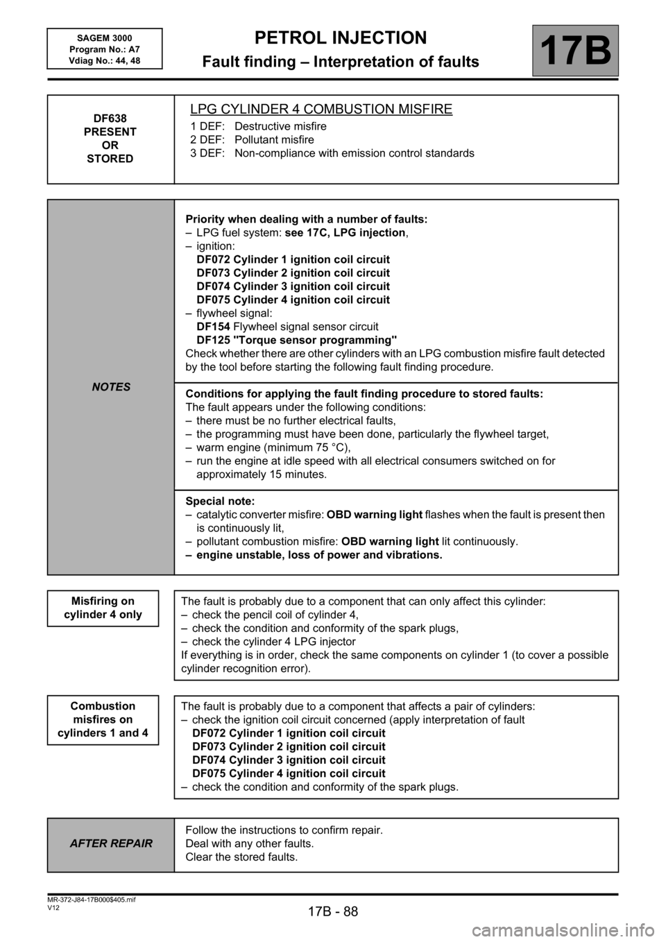
DF638
PRESENT
OR
STOREDLPG CYLINDER 4 COMBUSTION MISFIRE
1 DEF: Destructive misfire
2 DEF: Pollutant misfire
3 DEF: Non-compliance with emission control standards
NOTESPriority when dealing with a number of faults:
– LPG fuel system: see 17C, LPG injection,
– ignition:
DF072 Cylinder 1 ignition coil circuit
DF073 Cylinder 2 ignition coil circuit
DF074 Cylinder 3 ignition coil circuit
DF075 Cylinder 4 ignition coil circuit
– flywheel signal:
DF154 Flywheel signal sensor circuit
DF125 "Torque sensor programming"
Check whether there are other cylinders with an LPG combustion misfire fault detected
by the tool before starting the following fault finding procedure.
Conditions for applying the fault finding procedure to stored faults:
The fault appears under the following conditions:
– there must be no further electrical faults,
– the programming must have been done, particularly the flywheel target,
– warm engine (minimum 75 °C),
– run the engine at idle speed with all electrical consumers switched on for
approximately 15 minutes.
Special note:
– catalytic converter misfire: OBD warning light flashes when the fault is present then
is continuously lit,
– pollutant combustion misfire: OBD warning light lit continuously.
– engine unstable, loss of power and vibrations.
Misfiring on
cylinder 4 only
The fault is probably due to a component that can only affect this cylinder:
– check the pencil coil of cylinder 4,
– check the condition and conformity of the spark plugs,
– check the cylinder 4 LPG injector
If everything is in order, check the same components on cylinder 1 (to cover a possible
cylinder recognition error).
The fault is probably due to a component that affects a pair of cylinders:
– check the ignition coil circuit concerned (apply interpretation of fault
DF072 Cylinder 1 ignition coil circuit
DF073 Cylinder 2 ignition coil circuit
DF074 Cylinder 3 ignition coil circuit
DF075 Cylinder 4 ignition coil circuit
– check the condition and conformity of the spark plugs.
Combustion
misfires on
cylinders 1 and 4
AFTER REPAIRFollow the instructions to confirm repair.
Deal with any other faults.
Clear the stored faults.
Page 89 of 181
PETROL INJECTION
Fault finding – Interpretation of faults17B
17B - 89V12 MR-372-J84-17B000$405.mif
SAGEM 3000
Program No.: A7
Vdiag No.: 44, 48
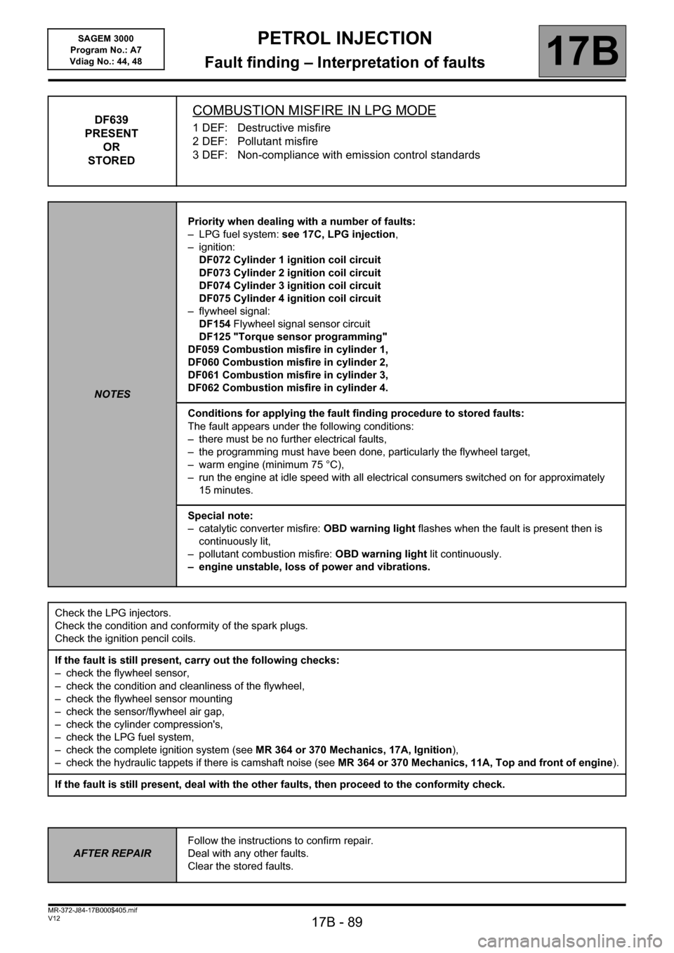
DF639
PRESENT
OR
STOREDCOMBUSTION MISFIRE IN LPG MODE
1 DEF: Destructive misfire
2 DEF: Pollutant misfire
3 DEF: Non-compliance with emission control standards
NOTESPriority when dealing with a number of faults:
– LPG fuel system: see 17C, LPG injection,
– ignition:
DF072 Cylinder 1 ignition coil circuit
DF073 Cylinder 2 ignition coil circuit
DF074 Cylinder 3 ignition coil circuit
DF075 Cylinder 4 ignition coil circuit
– flywheel signal:
DF154 Flywheel signal sensor circuit
DF125 "Torque sensor programming"
DF059 Combustion misfire in cylinder 1,
DF060 Combustion misfire in cylinder 2,
DF061 Combustion misfire in cylinder 3,
DF062 Combustion misfire in cylinder 4.
Conditions for applying the fault finding procedure to stored faults:
The fault appears under the following conditions:
– there must be no further electrical faults,
– the programming must have been done, particularly the flywheel target,
– warm engine (minimum 75 °C),
– run the engine at idle speed with all electrical consumers switched on for approximately
15 minutes.
Special note:
– catalytic converter misfire: OBD warning light flashes when the fault is present then is
continuously lit,
– pollutant combustion misfire: OBD warning light lit continuously.
– engine unstable, loss of power and vibrations.
Check the LPG injectors.
Check the condition and conformity of the spark plugs.
Check the ignition pencil coils.
If the fault is still present, carry out the following checks:
– check the flywheel sensor,
– check the condition and cleanliness of the flywheel,
– check the flywheel sensor mounting
– check the sensor/flywheel air gap,
– check the cylinder compression's,
– check the LPG fuel system,
– check the complete ignition system (see MR 364 or 370 Mechanics, 17A, Ignition),
– check the hydraulic tappets if there is camshaft noise (see MR 364 or 370 Mechanics, 11A, Top and front of engine).
If the fault is still present, deal with the other faults, then proceed to the conformity check.
AFTER REPAIRFollow the instructions to confirm repair.
Deal with any other faults.
Clear the stored faults.
Page 104 of 181

PETROL INJECTION
Fault finding – Conformity check17B
17B-104V12 MR-372-J84-17B000$450.mif
SAGEM 3000
Program No.: A7
Vdiag No.: 44, 48
HEATING SUB-FUNCTION
NOTESOnly check conformity after a thorough check with the diagnostic tool.
The values shown in this conformity check are given as a guide.
Application condition: engine off, ignition on.
Order FunctionParameter or Status
Checked or ActionDisplay and notes Fault finding
1Coolant
temperaturePR064: Coolant
temperature- 40°C < PR064 < 120°CIn the event of a fault,
apply the
interpretation of
DF001 Coolant
temperature sensor
circuit.
2
Passenger
compartment
heating
resistorET111: Number of
fixed heating
resistorsThis status indicates that the
injection computer is
preventing any change to the
number of passenger
compartment heating
resistors (RCH) activated
(RCH already activated are
not shut down, but no more
can be added). This limit in
the number of RCH is in
response to the vehicle's
requirements (power
availability, torque
requirement, etc.).WITHOUT
3ET112: Passenger
compartmen
t heating
resistor cut-
offThis status indicates that the
injection computer is
inhibiting all the passenger
compartment heating
resistors (RCH) in response
to the vehicle's requirements
(power availability,
torque requirement,
injection or air conditioning
defect mode, etc.).
JSAA741.0
Page 125 of 181

PETROL INJECTION
Fault finding – Conformity check17B
17B - 125V12 MR-372-J84-17B000$495.mif
SAGEM 3000
Program No.: A7
Vdiag No.: 44, 48
HEATING SUB-FUNCTION:
NOTESOnly check conformity after a full check with the diagnostic tool.
The values shown in this conformity check are given as a guide.
Application conditions: Engine warm, idling.
Order FunctionParameter or Status
checked or ActionDisplay and Notes Fault finding
1Coolant
temperaturePR064: Coolant
temperature75 °C < PR064 < 120 °CIf there is a fault use
the interpretation of
DF001 Coolant
temperature sensor
circuit.
2
RCHET111: RCH number
setThis status indicates that the
injection computer is
preventing any change to the
number of passenger
compartment heating resistors
(RCH) activated (RCH already
activated are not shut down,
but no more can be added).
This limit in the number of RCH
is in response to the vehicle's
requirements (power
availability, torque
requirement, etc.).NONE
3 ET112: RCH cut-offThis status indicates that the
injection computer is inhibiting
all the passenger compartment
heating resistors (RCH) in
response to the vehicle's
requirements (power
availability, torque
requirement, injection or air
conditioning defect mode,
etc.).
JSAA741.0
Page 135 of 181

PETROL INJECTION
Fault finding – Interpretation of statuses17B
17B - 135V12 MR-372-J84-17B000$540.mif
SAGEM 3000
Program No.: A7
Vdiag No.: 44, 48PETROL INJECTION
Fault finding – Interpretation of statuses
ET042
CONTINUED 1
INACTIVEWhen the main switch is in rest position (or neutral), status ET042 is INACTIVE.
If CRUISE CONTROL or SPEED LIMITER appears despite the main button being in the
rest (or neutral) position, carry out the following operations:
Check the connections on the steering column top control module.
Check for +12 V APC on track 9 of the steering column top control module
connector.
Disconnect the top steering column control module connector and with the switch in
the rest position, check the insulation between tracks 9 and 6 and between tracks 9
and 12.
Check the continuity of the top steering column control module connector between
tracks 9 and 6, with the switch in the speed limiter position.
Check the continuity of the steering column top control module connector on
tracks 9 and 12, with the control in the cruise control position.
If the these checks do not produce the correct results, replace the steering column top
control module.
AFTER REPAIRDeal with any other faults. Clear the fault memory.
Switch off the ignition and carry out a road test followed by a test with the diagnostic
tool.
JSAA741.0
Page 148 of 181

PETROL INJECTION
Fault finding – Interpretation of statuses17B
17B - 148V12 MR-372-J84-17B000$540.mif
SAGEM 3000
Program No.: A7
Vdiag No.: 44, 48
ET415
1(CONTINUED)
STATUS 2Brake pedal depressed
The cruise control function is deactivated when the brake pedal is depressed.
Status ET415 becomes STATUS 2 when driving with cruise control active (ET042
Cruise control/Speed limiter: CRUISE CONTROL) and the brake pedal is depressed.
This deactivates cruise control.
Reinitialise status ET415 on the injection computer by running command RZ007
“Fault memory”.
If status ET415 becomes STATUS 2 without depressing the brake pedal, consult the
interpretation of statuses ET704 Brake switch no. 1 and ET705 Brake switch no. 2.
STATUS 3Clutch pedal depressed
Manual gearbox ONLY
The cruise control function is deactivated when the gearbox is not coupled to the engine
(clutch pedal depressed).
Status ET415 becomes STATUS 3 when driving with cruise control active (ET042
Cruise control/speed limiter: CRUISE CONTROL) and the clutch pedal is depressed.
This deactivates cruise control.
Reinitialise status ET415 on the injection computer by running command RZ007
“Fault memory”.
If status ET415 becomes STATUS 3 without the clutch pedal being depressed, consult
the interpretation of status ET405: Clutch pedal.
If the vehicle is fitted with an automatic transmission:
Test the multiplex network: check the configuration of the multiplex network in relation to
the vehicle's technical specification, especially the configuration of the automatic
transmission computer (see 88B, Multiplexing)
STATUS 4Cancel button pressed
The cruise control/speed limiter function is deactivated whenever the suspend button is
pressed.
Status ET415 becomes STATUS 4 while driving when:
- the cruise control is active, or
- The speed limiter is active,
- and the driver presses the 0 button.
This action deactivates the Cruise control/Speed limiter.
Reinitialise status ET415 on the injection computer by running command RZ007
“Fault memory”.
If status ET415 becomes STATUS 4 without pressing the 0 button, consult the
interpretation of status ET703 Cruise control/speed limiter buttons and run fault
finding on the R/0 control button located on the right-hand side of the steering wheel.
AFTER REPAIRDeal with any other faults. Clear the fault memory.
Switch off the ignition and carry out a road test followed by a test with the diagnostic
tool
JSAA741.0
Page 152 of 181
PETROL INJECTION
Fault finding – Interpretation of statuses17B
17B - 152V12 MR-372-J84-17B000$540.mif
SAGEM 3000
Program No.: A7
Vdiag No.: 44, 48
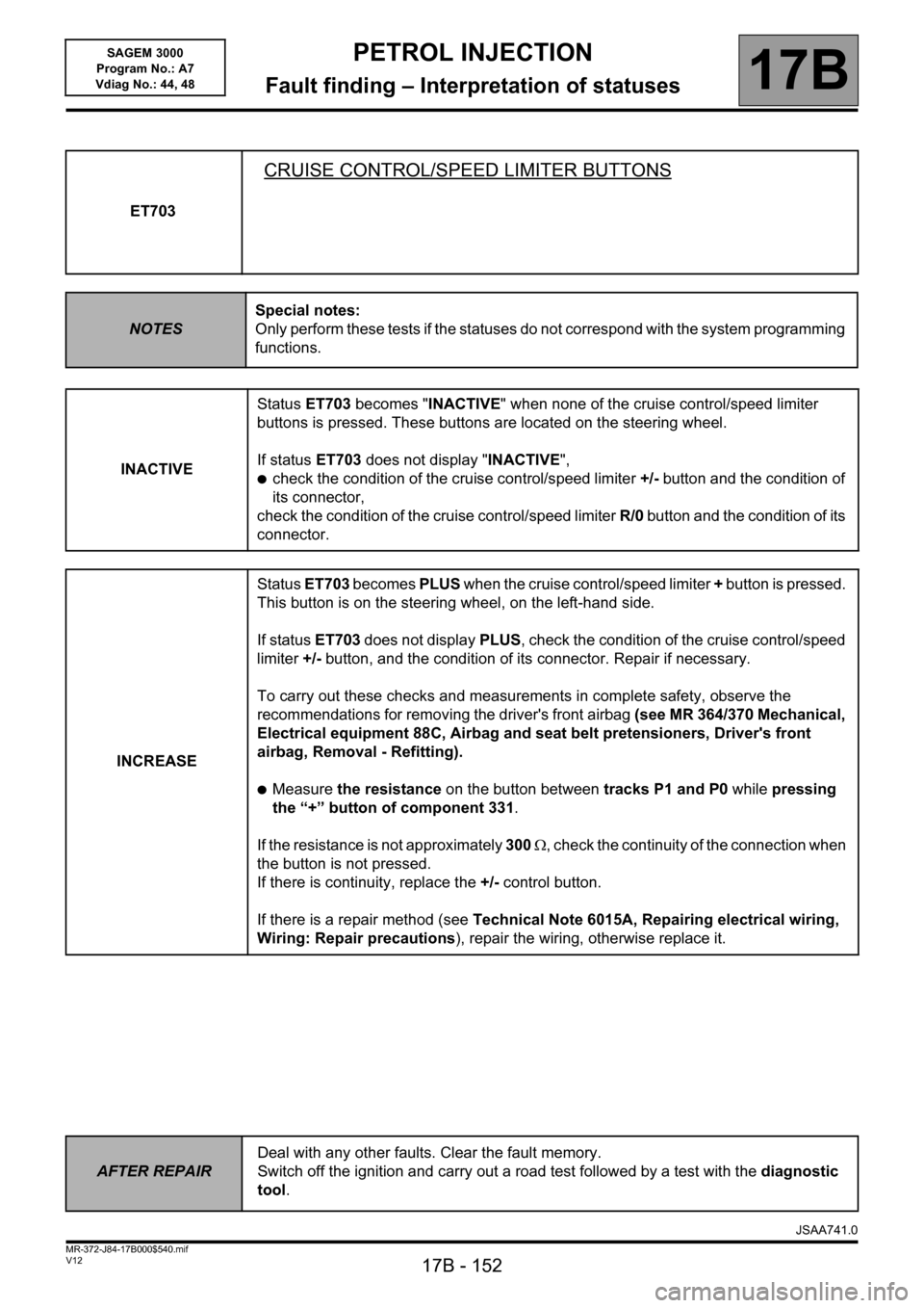
ET703
CRUISE CONTROL/SPEED LIMITER BUTTONS
NOTESSpecial notes:
Only perform these tests if the statuses do not correspond with the system programming
functions.
INACTIVEStatus ET703 becomes "INACTIVE" when none of the cruise control/speed limiter
buttons is pressed. These buttons are located on the steering wheel.
If status ET703 does not display "INACTIVE",
●check the condition of the cruise control/speed limiter +/- button and the condition of
its connector,
check the condition of the cruise control/speed limiter R/0 button and the condition of its
connector.
INCREASEStatus ET703 becomes PLUS when the cruise control/speed limiter + button is pressed.
This button is on the steering wheel, on the left-hand side.
If status ET703 does not display PLUS, check the condition of the cruise control/speed
limiter +/- button, and the condition of its connector. Repair if necessary.
To carry out these checks and measurements in complete safety, observe the
recommendations for removing the driver's front airbag (see MR 364/370 Mechanical,
Electrical equipment 88C, Airbag and seat belt pretensioners, Driver's front
airbag, Removal - Refitting).
●Measure the resistance on the button between tracks P1 and P0 while pressing
the “+” button of component 331.
If the resistance is not approximately 300 , check the continuity of the connection when
the button is not pressed.
If there is continuity, replace the +/- control button.
If there is a repair method (see Technical Note 6015A, Repairing electrical wiring,
Wiring: Repair precautions), repair the wiring, otherwise replace it.
AFTER REPAIRDeal with any other faults. Clear the fault memory.
Switch off the ignition and carry out a road test followed by a test with the diagnostic
tool.
JSAA741.0
Page 155 of 181
PETROL INJECTION
Fault finding – Interpretation of statuses17B
17B - 155V12 MR-372-J84-17B000$540.mif
SAGEM 3000
Program No.: A7
Vdiag No.: 44, 48
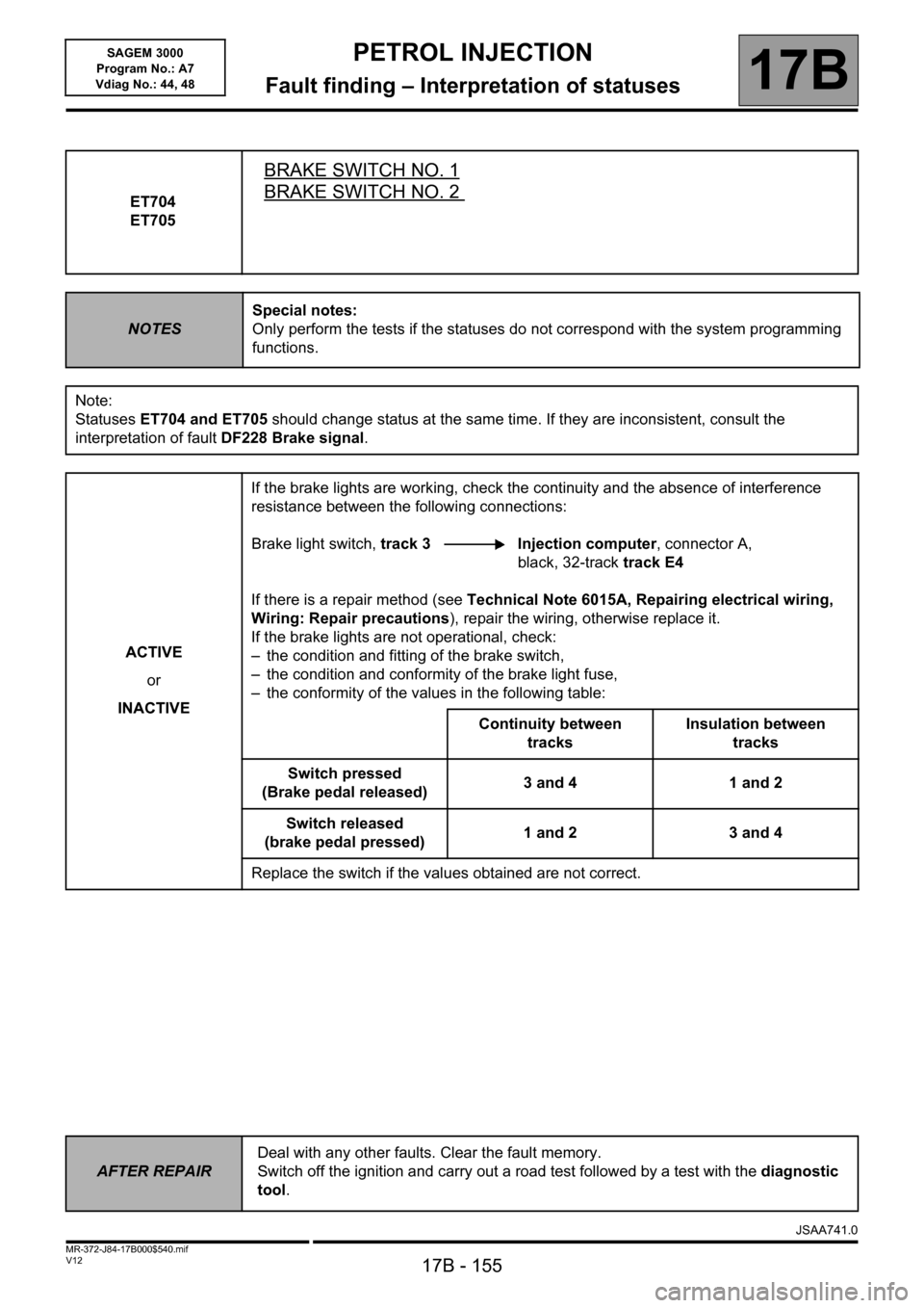
ET704
ET705
BRAKE SWITCH NO. 1
BRAKE SWITCH NO. 2
NOTESSpecial notes:
Only perform the tests if the statuses do not correspond with the system programming
functions.
Note:
Statuses ET704 and ET705 should change status at the same time. If they are inconsistent, consult the
interpretation of fault DF228 Brake signal.
ACTIVE
or
INACTIVEIf the brake lights are working, check the continuity and the absence of interference
resistance between the following connections:
Brake light switch, track 3 Injection computer, connector A,
black, 32-track track E4
If there is a repair method (see Technical Note 6015A, Repairing electrical wiring,
Wiring: Repair precautions), repair the wiring, otherwise replace it.
If the brake lights are not operational, check:
– the condition and fitting of the brake switch,
– the condition and conformity of the brake light fuse,
– the conformity of the values in the following table:
Continuity between
tracksInsulation between
tracks
Switch pressed
(Brake pedal released)3 and 4 1 and 2
Switch released
(brake pedal pressed)1 and 2 3 and 4
Replace the switch if the values obtained are not correct.
AFTER REPAIRDeal with any other faults. Clear the fault memory.
Switch off the ignition and carry out a road test followed by a test with the diagnostic
tool.
1JSAA741.0