RENAULT SCENIC 2014 J95 / 3.G Petrol Injection - Sagem3000 Workshop Manual
Manufacturer: RENAULT, Model Year: 2014, Model line: SCENIC, Model: RENAULT SCENIC 2014 J95 / 3.GPages: 181
Page 1 of 181

1Engine and peripherals
V12 MR-372-J84-17B000$TOC.mif
V12
17B
"The repair procedures given by the manufacturer in this document are based on the
technical specifications current when it was prepared.
The procedures may be modified as a result of changes introduced by the
manufacturer in the production of the various component units and accessories from
which his vehicles are constructed."
V12
All rights reserved by Renault s.a.s.
Edition Anglaise
Copying or translating, in part or in full, of this document or use of the service part
reference numbering system is forbidden without the prior written authority of
Renault s.a.s.
© Renault s.a.s. 2014
PETROL INJECTION
SAGEM 3000
Program No.: A7
Vdiag No.: 44, 48
Fault finding – Introduction 17B - 2
Fault finding – System operation 17B - 7
Fault finding – Allocation of computer tracks 17B - 12
Fault finding – Replacement of components 17B - 15
Fault finding – Configurations and programming 17B - 16
Fault finding – Fault summary table 17B - 17
Fault finding – Interpretation of faults 17B - 21
Fault finding – Conformity check 17B - 90
Fault finding – Status summary table 17B - 132
Fault finding – Interpretation of statuses 17B - 134
Fault finding – Parameter summary table 17B - 156
Fault finding – Interpretation of parameters 17B - 158
Fault finding – Command summary table 17B - 166
Fault finding – Interpretation of commands 17B - 167
Fault finding – Help 17B - 173
Fault finding – Customer complaints 17B - 175
Fault finding – Fault Finding Chart 17B - 176
Page 2 of 181

PETROL INJECTION
Fault finding – Introduction17B
17B-2V12 MR-372-J84-17B000$045.mif
117B
SAGEM 3000
Program No.: A7
Vdiag No.: 44, 48PETROL INJECTION
Fault finding – Introduction
1. SCOPE OF THIS DOCUMENT
This document presents the fault finding method applicable to all computers with the following specifications:
2. PREREQUISITES FOR FAULT FINDING
Documentation type
Fault finding procedures (this document):
– Assisted fault finding (integrated into the diagnostic tool), Dialogys.
Wiring Diagrams:
– Visu-Schéma (CD-ROM), paper.
Type of diagnostic tools
–CLIP
Special tooling required
3. REMINDERS
Procedure
To run fault finding on the vehicle's computers, switch on the ignition in fault finding mode (forced + after ignition
feed).
Proceed as follows:
– with the vehicle card in the card reader,
– press and hold Start button (longer than 5 seconds) with start-up conditions not fulfilled,
– connect the diagnostic tool and perform the required operations.
To cut off the + after ignition feed, proceed as follows:
– disconnect the diagnostic tool,
– press the Start button twice briefly (less than 3 seconds),
– Check that the + after ignition feed has been cut off by checking that the computer warning lights on the instrument
panel have gone out. Vehicle(s): Mégane II / Mégane Sport / Scénic II
Function concerned: Petrol injectionName of computer: Sagem S3000
Program no.: A7
Vdiag No.: 44, 48
Special tooling required
Multimeter
Elé. 1497Bornier
Elé. 1681Universal bornier
Note:
The left-hand and right-hand xenon bulb computers are powered when the dipped headlights are lit.
Fault finding procedures can only be carried out on them after the ignition has been switched on in fault finding
mode (+ after ignition imposed) and the dipped headlights are on.
S3000_V44_PRELI/S3000_V48_PRELI
MR-372-J84-17B000$045.mif
Page 3 of 181

PETROL INJECTION
Fault finding – Introduction17B
17B-3V12 MR-372-J84-17B000$045.mif
SAGEM 3000
Program No.: A7
Vdiag No.: 44, 48
Faults
Faults are declared present or stored (depending on whether they appeared in a certain context and have
disappeared since, or whether they remain present but are not diagnosed within the current context).
The present or stored status of faults should be taken into consideration when the diagnostic tool is switched on
following + after ignition feed being activated (without any system components being active).
For a present fault, apply the procedure described in the Interpretation of faults section.
For a stored fault, note the faults displayed and apply the Notes section.
If the fault is confirmed when the instructions in the Notes section are applied, the fault is present. Deal with the
fault.
If the fault is not confirmed, check:
– the electrical lines which correspond to the fault,
– the connectors for these lines (for oxidation, bent pins, etc.),
– the resistance of the component detected as faulty,
– the condition of the wires (melted or split insulation, wear).
Conformity check
The aim of the conformity check is to check the statuses and parameters that do not produce a fault display on the
diagnostic tool when they are inconsistent. Therefore, this stage is used to:
– carry out fault finding on faults that do not have a fault display, and which may correspond to a customer complaint.
– check that the system is operating correctly and that there is no risk of a fault recurring after repairs.
This section gives the fault finding procedures for statuses and parameters and the conditions for checking them.
If a status is not behaving normally or a parameter is outside the permitted tolerance values, consult the
corresponding fault finding page.
Customer complaints - Fault finding chart
If the test with the diagnostic tool is OK but the customer complaint is still present, the fault should be treated by
customer complaints.
A summary of the overall procedure to follow is provided on the following
page in the form of a flow chart.
JSAA741.0
Page 4 of 181

PETROL INJECTION
Fault finding – Introduction17B
17B-4V12 MR-372-J84-17B000$045.mif
SAGEM 3000
Program No.: A7
Vdiag No.: 44, 48
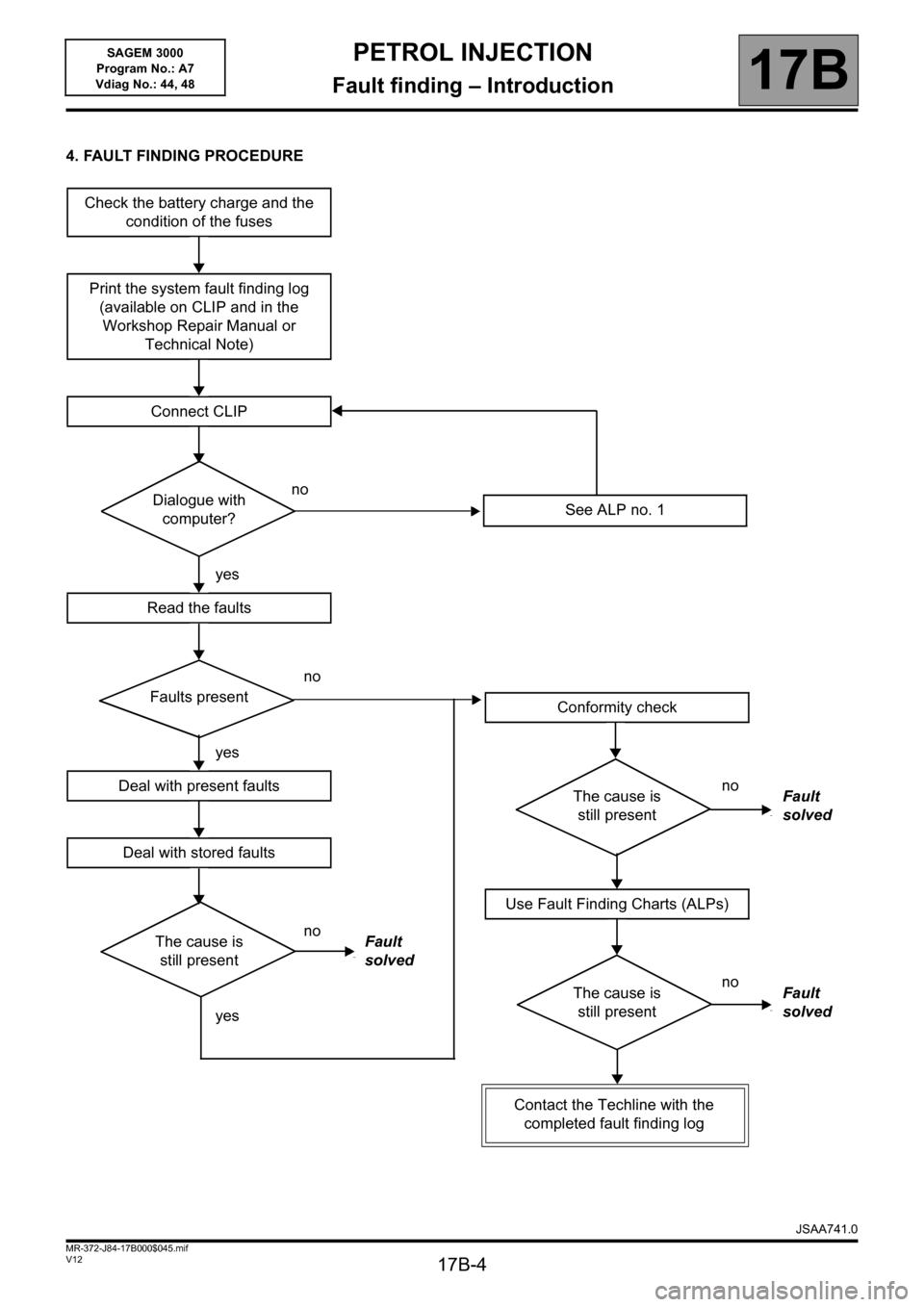
4. FAULT FINDING PROCEDURE
Check the battery charge and the
condition of the fuses
Print the system fault finding log
(available on CLIP and in the
Workshop Repair Manual or
Technical Note)
Connect CLIP
no
Dialogue with
computer?
yes
Read the faults
no
Faults present
yes
Deal with present faults
Deal with stored faults
no
The cause is
still presentFault
solved
yes
See ALP no. 1
Conformity check
no
The cause is
still presentFault
solved
Use Fault Finding Charts (ALPs)
no
The cause is
still presentFault
solved
Contact the Techline with the
completed fault finding log
JSAA741.0
Page 5 of 181

PETROL INJECTION
Fault finding – Introduction17B
17B-5V12 MR-372-J84-17B000$045.mif
SAGEM 3000
Program No.: A7
Vdiag No.: 44, 48
4. FAULT FINDING PROCEDURE (continued)
Wiring check
Fault finding problems
Disconnecting the connectors and/or manipulating the wiring may temporarily remove the cause of a fault.
Electrical measurements of the voltage, resistance and insulation are generally correct, especially if the fault is not
present when analysing (stored fault).
Visual inspection
Look for damage under the bonnet and in the passenger compartment.
Carefully check the fuses, insulators and wiring harness routing.
Look for signs of oxidation.
Physical inspection
While manipulating the wiring, use the diagnostic tool to note any change in fault status from stored to present.
Make sure that the connectors are properly locked.
Apply light pressure to the connectors.
Twist the wiring harness.
If there is a change in status, try to locate the source of the fault.
Inspection of each component
Disconnect the connectors and check the appearance of the clips and tabs, as well as their crimping (no crimping on
the insulating section).
Make sure that the clips and tabs are properly locked in the sockets.
Check that no clips or tabs have been dislodged during connection.
Check the clip contact pressure using an appropriate model of tab.
Resistance check
Check the continuity of entire lines, then section by section.
Look for a short circuit to earth, to + 12 V or with another wire.
If a fault is detected, repair or replace the wiring harness.
JSAA741.0
Page 6 of 181

PETROL INJECTION
Fault finding – Introduction17B
17B-6V12 MR-372-J84-17B000$045.mif
SAGEM 3000
Program No.: A7
Vdiag No.: 44, 48
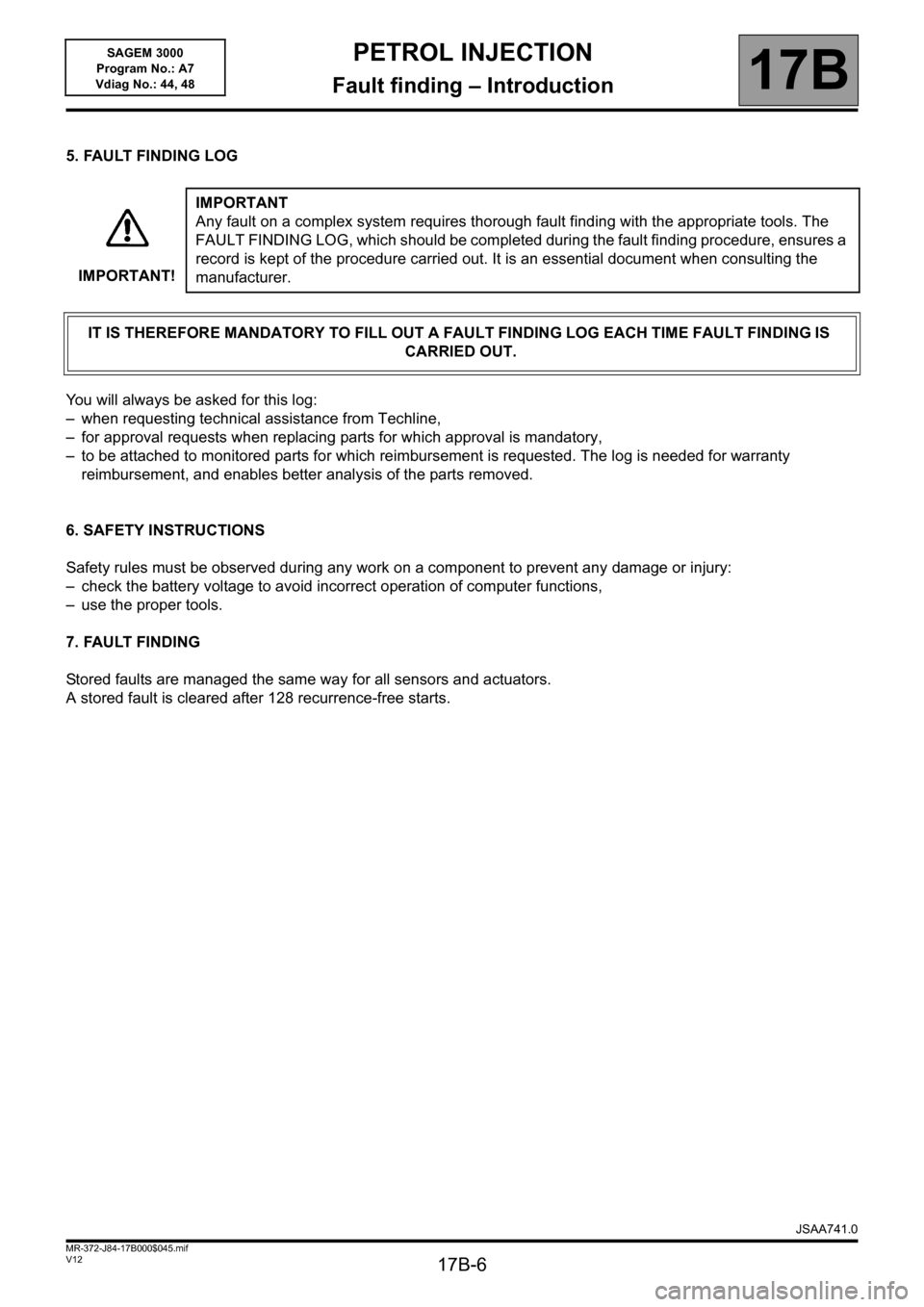
5. FAULT FINDING LOG
You will always be asked for this log:
– when requesting technical assistance from Techline,
– for approval requests when replacing parts for which approval is mandatory,
– to be attached to monitored parts for which reimbursement is requested. The log is needed for warranty
reimbursement, and enables better analysis of the parts removed.
6. SAFETY INSTRUCTIONS
Safety rules must be observed during any work on a component to prevent any damage or injury:
– check the battery voltage to avoid incorrect operation of computer functions,
– use the proper tools.
7. FAULT FINDING
Stored faults are managed the same way for all sensors and actuators.
A stored fault is cleared after 128 recurrence-free starts.IMPORTANT!IMPORTANT
Any fault on a complex system requires thorough fault finding with the appropriate tools. The
FAULT FINDING LOG, which should be completed during the fault finding procedure, ensures a
record is kept of the procedure carried out. It is an essential document when consulting the
manufacturer.
IT IS THEREFORE MANDATORY TO FILL OUT A FAULT FINDING LOG EACH TIME FAULT FINDING IS
CARRIED OUT.
JSAA741.0
Page 7 of 181

PETROL INJECTION
Fault finding – System operation17B
17B - 7V12 MR-372-J84-17B000$090.mif
SAGEM 3000
Program No.: A7
Vdiag No.: 44, 48PETROL INJECTION
Fault finding – System operation
1. SYSTEM OPERATION
Composition
The injection system consists of the:
– accelerator potentiometer,
– accelerator pedal switch,
– TDC sensor,
– atmospheric pressure sensor,
– air temperature sensor,
– coolant temperature sensor,
– freon pressure sensor,
– upstream oxygen sensor,
– downstream oxygen sensor,
– cruise control switch,
– steering column switch,
– cruise control on/off switch,
– brake lights switch,
– fuel vapour absorber,
– injection computer,
– motorised throttle valve,
– four injectors,
– four pencil coils,
– + turbocharging pressure sensor,
– coolant pump
– turbocharging solenoid valve.
Computer
SAGEM S3000 flash EEPROM 128-track computer controlling the injection and the ignition.
Multipoint injection in sequential mode.
Connections to the other computers:
– Protection and Switching Unit (UPC)
– Passenger Compartment Control Unit (UCH),
– Automatic Transmission Electronic Control Unit (AUTO ECU).
JSAA741.0
MR-372-J84-17B000$090.mif
Page 8 of 181

PETROL INJECTION
Fault finding – System operation17B
17B - 8V12 MR-372-J84-17B000$090.mif
SAGEM 3000
Program No.: A7
Vdiag No.: 44, 48
Engine immobiliser
The immobiliser function is managed by the UCH and engine management computers.
Before any driver request (card + button press), the engine management and UCH computers exchange
authentication CAN frames to determine whether or not to start the engine.
After more than five consecutive failed authentication attempts, the engine management computer goes into
protection (anti-scanning) mode and no longer tries to authenticate the UCH computer. It only leaves this mode when
the following sequence of operations is carried out:
– the ignition is left on for at least 60 seconds,
– ignition is switched off,
– the injection computer self-supply cuts out when it should (the time varies according to engine temperature).
After this, only one authentication attempt is allowed. If it too fails, the sequence of operations described above must
be repeated.
If the engine management computer still fails to unlock, contact the Techline.
Impact detected
If an impact has been registered by the injection computer (Impact detected), switch off the ignition for 10 seconds
then switch it back on to start the engine. Then clear any faults.
WARNING
Disconnect the injection computer when carrying out any welding work on the vehicle.
JSAA741.0
Page 9 of 181

PETROL INJECTION
Fault finding – System operation17B
17B - 9V12 MR-372-J84-17B000$090.mif
SAGEM 3000
Program No.: A7
Vdiag No.: 44, 48
2. OPERATIONAL SAFETY
Warning lights illumination
The S3000 injection system manages the illumination of three warning lights and the issuing of warning messages
according to the severity of the faults detected, to inform the customer and to direct fault finding.
The injection computer manages the illumination of warning lights and warning messages displayed on the instrument
panel. These warning lights illuminate during the starting phase and in the event of an injection fault or engine
overheating.
The warning light illumination signals reach the instrument panel via the multiplex network.
Warning light illumination principle
During the starting phase (START button pressed) the OBD (On Board Diagnostic) warning light comes on for
approximately 3 seconds then goes out.
If there is an injection fault (severity 1), the INJECTION FAULT written message lights up followed by the SERVICE
warning light. It indicates a reduced level of operation and a limited safety level.
The driver should carry out repairs as soon as possible.
Components involved:
– motorised throttle valve,
– accelerator pedal potentiometer,
– inlet manifold pressure sensor,
–computer,
– actuator feed,
– computer feed.
If there is a serious injection fault (severity 2), the red engine symbol and the word STOP appear (display with
information display only), with the ENGINE OVERHEATING written message followed by the STOP warning light
and a buzzer. If this happens, the vehicle must be stopped immediately.
When a fault causing excessive pollution in the exhaust fumes is detected, the orange OBD warning light, an engine
symbol, will be lit:
–flashing in the event of a fault which might irreparably damaged the catalytic converter (destructive misfire). If this
happens you must stop the vehicle immediately,
–constantly in the case of non-compliance with the anti-pollution standards (pollutant misfire, catalytic converter
fault, oxygen sensor faults, inconsistency between the oxygen sensors and canister fault).
Mileage travelled with fault
This parameter serves to measure the distance travelled with one of the injection fault warning lights on: level 1 fault
warning light (amber), coolant temperature overheating warning light, or OBD warning light.
The counter can be reset to 0 using the diagnostic tool.
JSAA741.0
Page 10 of 181

PETROL INJECTION
Fault finding – System operation17B
17B - 10V12 MR-372-J84-17B000$090.mif
SAGEM 3000
Program No.: A7
Vdiag No.: 44, 48
Defect modes
Motorised throttle valve
In defect mode, the motorised throttle valve can have 6 different statuses.
Type 1
The throttle opening is less than the Safe mode position. The throttle is no longer activated and is
automatically in Safe mode. The ESP, distance control and cruise control/speed limiter systems are
disabled. The automatic transmission is in "Safe mode".
Type 2
The throttle opening is no longer actuated. The engine speed is limited by injection cut-off.
Type 3
Defect mode is associated with restructuring of the pedal setpoints (constant pedal setpoint for each gear).
Type 4
The associated defect mode restricts the throttle opening. The maximum throttle valve opening threshold
results in a speed below 54 mph (90 km/h).
Type 5
The computer no longer processes torque changes requested by the ESP, distance control, cruise control/
speed limiter and automatic gearbox systems.
This defect mode results from a computer malfunction, or a fault with the manifold or turbocharging
pressure sensor.
The system then only uses the accelerator pedal signal.
The ESP, distance control and cruise control/speed limiter systems are disabled. The automatic
transmission system is in Safe mode.
Type 6
The turbocharging valve no longer works.
JSAA741.0