air filter RENAULT TWINGO 2009 2.G Air Conditioning User Guide
[x] Cancel search | Manufacturer: RENAULT, Model Year: 2009, Model line: TWINGO, Model: RENAULT TWINGO 2009 2.GPages: 122
Page 45 of 122
61A-42
HEATING
Distribution unit: Removal - Refitting
CLIMATE CONTROL
61A
aRefit the storage compartment.
aRefit the radio (see Radio: Removal - Refitting)
(86A, Radio).
aRefit the tweeters (see Tweeter: Removal - Refit-
ting) (86A, Radio).
aRefit:
-the control panel (see 61A, Heating, Control pan-
el: Removal - Refitting, page 61A-65) ,
-the instrument panel (see Instrument panel: Re-
moval - Refitting) (83A, Instrument panel),
-the passenger front airbag (see Passenger's fron-
tal airbag: Removal - Refitting) (88C, Airbags
and pretensioners),
-the steering column switch assembly (see Steer-
ing column switch assembly: Removal - Refit-
ting) (84A, Control - Signals),
-the steering wheel (see Steering wheel: Removal
- Refitting) (36A, Steering assembly),
-the driver's front airbag (see Driver's frontal air-
bag: Removal - Refitting) (88C, Airbags and seat
belt pretensioners).
aRefit the rev counter (see Rev counter: Removal -
Refitting) (83A, Instrument panel).
aConnect:
-the air filter unit air inlet pipe onto the air filter unit,
-the heater matrix inlet and outlet hoses.aFit the heater matrix inlet and outlet hose clips using
the (Mot. 1448) or (Mot. 1202-01) or (Mot. 1202-
02).
aRemove the (Ms. 583) on the heater matrix inlet and
outlet hoses.
aRefit the air outlet pipe onto the air filter unit.
aFit the air filter unit air inlet pipe.
aRemove the plugs from the openings.
aFit the connecting pipes.
aRefit:
-the bolt to the expansion valve - compressor con-
necting pipe,
-the bolt to the condenser - expansion valve con-
necting pipe.
aRefit:
-the scoop under the scuttle panel grille (see Scoop
under the scuttle panel grille: Removal - Refit-
ting) (56A, Exterior equipment),
-the scuttle panel grille (see Scuttle panel grille:
Removal - Refitting) (56A, Exterior equipment),
-the windscreen wiper arms (see Windscreen wip-
er arm: Removal - Refitting) (85A, Wiping -
Washing).
aConnect the battery (see Battery: Removal - Refit-
ting) (80A, Battery).
aUnlock the airbag computer using the Diagnostic
tool (see Fault finding - Replacement of compo-
nents) (88C, Airbags and pretensioners).
aFill up and bleed the cooling system (see Cooling
system: Draining - Refilling) (19A, Cooling).
aCheck the cooling circuit (see Engine cooling sys-
tem: Check) (19A, Cooling).
aConsult the refrigerant and oil quantity values before
filling the circuit (see 62A, Air conditioning, Air
conditioning: Parts and consumables for the re-
pair, page 62A-2) .
aFill the refrigerant circuit using the refrigerant
charging station (see 62A, Air conditioning, Re-
frigerant circuit: Draining - Filling, page 62A-8) .
aCheck that the air conditioning system is operating
correctly (see 62A, Air conditioning, Air condi-
tioning: Check, page 62A-4) . WITH 2 SPEAKERS, WITHOUT RADIO or VEHI-
CLE WITHOUT RADIO
RADIO NO. 01 or RADIO NO. 03
WITH 2 SPEAKERS, WITHOUT RADIO or RADIO
NO. 01 or RADIO NO. 03
ENGINE REV COUNTER
D7F
Page 47 of 122
61A-44
HEATING
Heater matrix: Removal - Refitting
LEFT-HAND DRIVE
61A
REMOVAL
I - REMOVAL PREPARATION OPERATION
aLock the airbag computer using the Diagnostic tool
(see Fault finding - Replacement of components)
(88C, Airbags and pretensioners).
aDisconnect the battery (see Battery: Removal - Re-
fitting) (80A, Battery).
aRemove:
-the windscreen wiper arms (see Windscreen wip-
er arm: Removal - Refitting) (85A, Wiping -
Washing),
-the scuttle panel grille (see Scuttle panel grille:
Removal - Refitting) (56A, Exterior equipment),
-the scoop under the scuttle panel grille (see Scoop
under the scuttle panel grille: Removal - Refit-
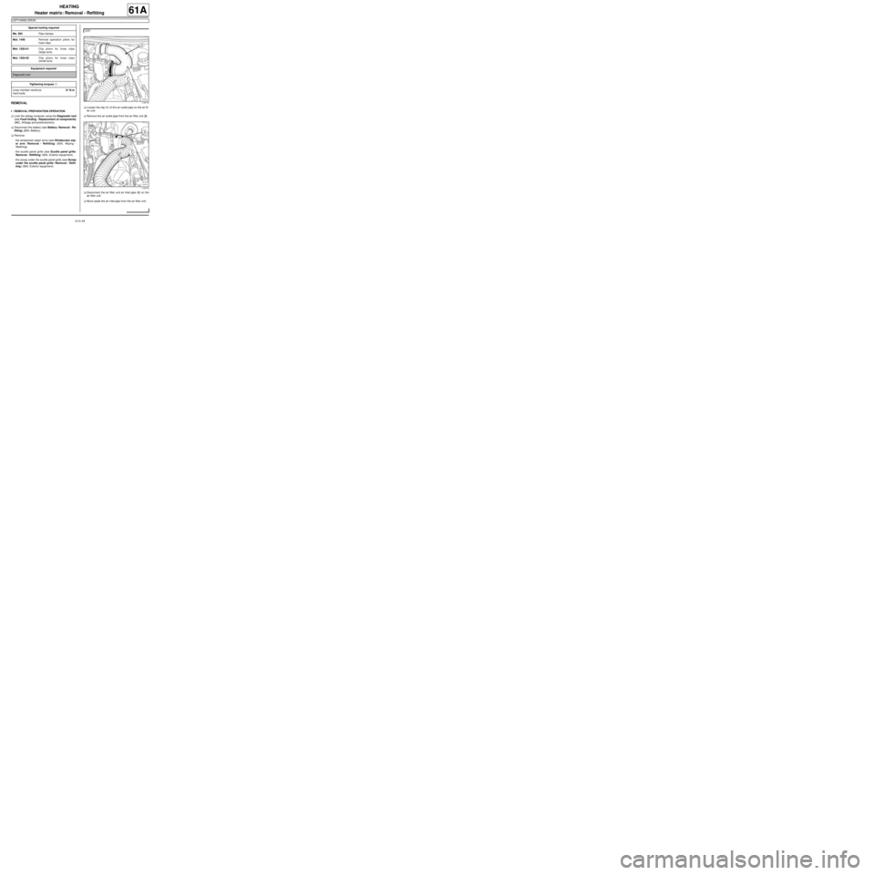
ting) (56A, Exterior equipment).aLoosen the clip (1) of the air outlet pipe on the air fil-
ter unit.
aRemove the air outlet pipe from the air filter unit (2) .
aDisconnect the air filter unit air inlet pipe (3) on the
air filter unit.
aMove aside the air inlet pipe from the air filter unit. Special tooling required
Ms. 583Pipe clamps .
Mot. 1448Remote operation pliers for
hose clips .
Mot. 1202-01Clip pliers for hose clips
(large size).
Mot. 1202-02Clip pliers for hose clips
(small size)
Equipment required
Diagnostic tool
Tightening torquesm
cross member reinforce-
ment bolts21 N.m
D7F
119715
119716
Page 50 of 122
61A-47
HEATING
Heater matrix: Removal - Refitting
LEFT-HAND DRIVE
61A
II - REFITTING OPERATION FOR PART
CONCERNED
aFit the pipes on the heater matrix with new seals.
aClip on the pipe bracket.
aRefit the heater matrix and its pipes.
aRefit:
-the heater matrix bolts.
-the heater matrix pipe bracket,
-the bolt on the heater matrix pipe bracket,
-the heater matrix pipe bracket on the distribution
unit,
-the heater matrix pipe bracket bolt on the distribu-
tion unit,
III - FINAL OPERATION
aRemove the protective cover on the floor carpet.
aRefit:
-the cross member reinforcement,
-the cross member reinforcement bolts,
aTorque tighten the cross member reinforcement
bolts (21 N.m).
aRefit:
-the dashboard (see Dashboard: Removal - Refit-
ting) (57A, Interior equipment),
-the centre console (see Centre console: Removal
- Refitting) (57A, Interior equipment).
aRefit the storage compartment.
aRefit the radio (see Radio: Removal - Refitting)
(86A, Radio).aRefit the tweeters (see Tweeter: Removal - Refit-
ting) (86A, Radio).
aRefit:
-the control panel (see 61A, Heating, Control pan-
el: Removal - Refitting, page 61A-65) ,
-the instrument panel (see Instrument panel: Re-
moval - Refitting) (83A, Instrument panel),
-the passenger front airbag (see Passenger's fron-
tal airbag: Removal - Refitting) (88C, Airbags
and pretensioners),
-the steering column switch assembly (see Steer-
ing column switch assembly: Removal - Refit-
ting) (84A, Control - Signals),
-the steering wheel (see Centre console: Removal
- Refitting) (36A, Steering assembly),
-the driver's front airbag (see Driver's frontal air-
bag: Removal - Refitting) (88C, Airbags and seat
belt pretensioners).
aRefit the rev counter (see Rev counter: Removal -
Refitting) (83A, Instrument panel).
aRefit the air outlet pipe onto the air filter unit.
aFit the air filter unit air inlet pipe.
aRefit the air filter unit air inlet pipe on the air filter unit
aRefit the heater matrix inlet and outlet hoses.
aFit the heater matrix inlet and outlet hose clips using
the (Mot. 1448) or (Mot. 1202-01) or (Mot. 1202-
02).
aRemove the (Ms. 583) on the heater matrix inlet and
outlet hoses. WITH 2 SPEAKERS, WITHOUT RADIO or VEHI-
CLE WITHOUT RADIO
RADIO NO. 01 or RADIO NO. 03
WITH 2 SPEAKERS, WITHOUT RADIO or RADIO
NO. 01 or RADIO NO. 03
ENGINE REV COUNTER
D7F
Page 52 of 122
61A-49
HEATING
Heater matrix: Removal - Refitting
RIGHT-HAND DRIVE
61A
REMOVAL
I - REMOVAL PREPARATION OPERATION
aLock the airbag computer using the Diagnostic tool
(see Fault finding - Replacement of components)
(88C, Airbags and pretensioners).
aDisconnect the battery (see Battery: Removal - Re-
fitting) (80A, Battery).
aRemove:
-the windscreen wiper arms (see Windscreen wip-
er arm: Removal - Refitting) (85A, Wiping -
Washing),
-the scuttle panel grille (see Scuttle panel grille:
Removal - Refitting) (56A, Exterior equipment),
-the scoop under the scuttle panel grille (see Scoop
under the scuttle panel grille: Removal - Refit-
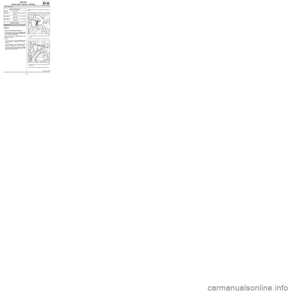
ting) (56A, Exterior equipment).aLoosen the clip (1) of the air outlet pipe on the air fil-
ter unit.
aRemove the air outlet pipe from the air filter unit (2) .
aDisconnect the air filter unit air inlet pipe (3) on the
air filter unit.
aMove aside the air inlet pipe from the air filter unit. Special tooling required
Ms. 583Pipe clamps .
Mot. 1448Remote operation pliers for
hose clips .
Mot. 1202-01Clip pliers for hose clips
(large size).
Mot. 1202-02Clip pliers for hose clips
(small size)
Equipment required
Diagnostic tool
D7F
119715
119716
Page 55 of 122
61A-52
HEATING
Heater matrix: Removal - Refitting
RIGHT-HAND DRIVE
61A
-the instrument panel (see Instrument panel: Re-
moval - Refitting) (83A, Instrument panel),
-the passenger front airbag (see Passenger's fron-
tal airbag: Removal - Refitting) (88C, Airbags
and pretensioners),
-the steering column switch assembly (see Steer-
ing column switch assembly: Removal - Refit-
ting) (84A, Control - Signals),
-the steering wheel (see Centre console: Removal
- Refitting) (36A, Steering assembly),
-the driver's front airbag (see Driver's frontal air-
bag: Removal - Refitting) (88C, Airbags and seat
belt pretensioners).
aRefit the rev counter (see Rev counter: Removal -
Refitting) (83A, Instrument panel).
aRefit the air outlet pipe onto the air filter unit.
aFit the air filter unit air inlet pipe.
aConnect the air filter unit air inlet pipe on the air filter
unit.
aConnect the heater matrix inlet and outlet hoses.
aFit the heater matrix inlet and outlet hose clips using
the (Mot. 1448) or (Mot. 1202-01) or (Mot. 1202-
02).
aRemove the (Ms. 583) from the heater matrix inlet
and outlet hoses.
aRefit:
-the scoop under the scuttle panel grille (see Scoop
under the scuttle panel grille: Removal - Refit-
ting) (56A, Exterior equipment),
-the scuttle panel grille (see Scuttle panel grille:
Removal - Refitting) (56A, Exterior equipment),
-the windscreen wiper arms (see Windscreen wip-
er arm: Removal - Refitting) (85A, Wiping -
Washing).
aConnect the battery (see Battery: Removal - Refit-
ting) (80A, Battery).aUnlock the airbag computer using the Diagnostic
tool (see Fault finding - Replacement of compo-
nents) (88C, Airbags and pretensioners).
aFill up and bleed the cooling system (see Cooling
system: Draining - Refilling) (19A, Cooling).
aCheck the cooling circuit (see Engine cooling sys-
tem: Check) (19A, Cooling).
ENGINE REV COUNTER
D7F
Page 102 of 122
62A-21
AIR CONDITIONING
Expansion valve: Removal - Refitting
AIR CONDITIONING or CLIMATE CONTROL
62A
REMOVAL
I - REMOVAL PREPARATION OPERATION
a
aDrain the refrigerant circuit using a refrigerant
charging station (see 62A, Air conditioning, Re-
frigerant circuit: Draining - Filling, page 62A-8) .
aDisconnect the battery (see ) (80A, Battery).
aRemove:
-the wiper arms (see Windscreen wiper arm: Re-
moval - Refitting) (85A, Wiping - Washing),
-the scuttle panel grille (see Scuttle panel grille:
Removal - Refitting) (56A, Exterior equipment),
-the scoop under the scuttle panel grille (see Scoop
under the scuttle panel grille: Removal - Refit-
ting) (56A, Exterior equipment).
aRemove:
-the air filter unit (see Air filter unit: Removal - Re-
fitting) (12A, Fuel mixture),
-the upstream oxygen sensor (see Oxygen sen-
sors: Removal - Refitting) (17B, Petrol injection). Equipment requiredrefrigerant charging station
compressed air nozzle
IMPORTANT
To avoid all risk of damage to the systems, apply
the safety and cleanliness instructions and opera-
tion recommendations before carrying out any
repair:
- (see 62A, Air conditioning, Air conditioning:
Precautions for the repair, page 62A-1) ,
- (see Vehicle: Precautions for the repair) (01D,
Mechanical introduction).
Note:
Use blanking plugs for the fuel circuits with part
numbers 77 01 208 229 or 77 01 476 857 to plug
any openings exposed to the open air. They must
be clean. Do not use any which have already been
used to plug a fuel circuit.
WARNING
To prevent moisture from entering the system,
place plugs on the cold loop components which are
open to the air.
WARNING
In order to avoid any refrigerant leaks, do not dam-
age (deform, twist, etc.) the pipe.
WARNING
To prevent the surrounding components from over-
heating, do not damage (tear, pierce, bend, etc.) a
heat shield.
Any damaged heat shields must be replaced.WARNING
Consult the device's operating manual to avoid
incorrect use.
D4F, and 780 – K4M, and 854
Page 105 of 122
62A-24
AIR CONDITIONING
Expansion valve: Removal - Refitting
AIR CONDITIONING or CLIMATE CONTROL
62A
-the air filter box (see Air filter unit: Removal - Re-
fitting) (12A, Fuel mixture).
aRefit:
-the scoop under the scuttle panel grille (see Scoop
under the scuttle panel grille: Removal - Refit-
ting) (56A, Exterior equipment),
-the scuttle panel grille (see Scuttle panel grille:
Removal - Refitting) (56A, Exterior equipment),
-the wiper arms (see Windscreen wiper arm: Re-
moval - Refitting) (85A, Wiping - Washing).
aConnect the battery (see ) (80A, Battery).
aConsult the amount of refrigerant and oil required
before filling the air conditioning circuit (see 62A, Air
conditioning, Air conditioning: Parts and con-
sumables for the repair, page 62A-2) .
aFill the refrigerant circuit using a refrigerant charg-
ing station (see 62A, Air conditioning, Refriger-
ant circuit: Draining - Filling, page 62A-8) .
aCheck for leaks (see 62A, Air conditioning, Refrig-
erant circuit: Check, page 62A-7) .
aCheck that the air conditioning system is operating
correctly (see 62A, Air conditioning, Air condi-
tioning: Check, page 62A-4) .
Page 107 of 122

62A-26
AIR CONDITIONING
Evaporator: Cleaning
AIR CONDITIONING or CLIMATE CONTROL
62A
CLEANING
I - CLEANING PREPARATION OPERATION
aRemove the cabin filter (see 61A, Heating, Cabin
filter: Removal - Refitting, page 61A-6) .
II - OPERATION FOR CLEANING PART
CONCERNED
aRemove any foreign matter (leaves, insects, etc.)
from the cabin filter housing.
a
Apply AIR CONDITIONING CLEANER using an ex-
tension piece. The end of the extension piece must
be positioned at the base of the evaporator.
aSpray the entire contents of the can.
aLeave the product to work for 15 minutes.
aRun the fan assembly very slowly for 5 minutes.
III - FINAL OPERATION.
aRefit the cabin filter (see 61A, Heating, Cabin filter:
Removal - Refitting, page 61A-6) . Note:
For the part number for the air conditioning
cleaner (see Vehicle: Parts and consumables
for the repair) (MR 411, 04B, Consumables -
Products).
WARNING
Do not spray the cleaner via the air inlet, as this
could damage the fan assembly.
Page 110 of 122
62A-29
AIR CONDITIONING
Dehydrator reservoir - expansion valve connecting pipe: Removal - Refitting
AIR CONDITIONING or CLIMATE CONTROL
62A
II - OPERATION FOR REMOVAL OF PART
CONCERNED
aRemove the nuts (1) from the connecting pipe brack-
et.
aMove aside the connecting pipes on the body.
aUncouple the « expansion valve - intermediate
pipe » connecting pipe from the « compressor - in-
termediate pipe » connecting pipe using tool (Mot.
1410) at (2) .aRemove the bolts (3) from the expansion valve con-
necting pipes.
aRemove the connecting pipes from the expansion
valve.
aInsert the blanking plugs.
aRemove:
-the air filter unit (see Air filter unit: Removal - Re-
fitting) (12A, Fuel mixture),
-the upstream oxygen sensor (see Oxygen sen-
sors: Removal - Refitting) (17B, Petrol injection).
aDisconnect the air temperature sensor.
121180
121178
D4F, and 780
K4M
Page 112 of 122
62A-31
AIR CONDITIONING
Dehydrator reservoir - expansion valve connecting pipe: Removal - Refitting
AIR CONDITIONING or CLIMATE CONTROL
62A
aClean the surface and seal of the pipe using EN-
GINE CLEANER (see Vehicle: Parts and con-
sumables for the repair) (04B, Consumables -
Products).
aUse a compressed air nozzle to blow on the sur-
face and the seal of the connecting pipe.
aLubricate the surface of the connecting pipe and the
seal with air conditioning oil (see 62A, Air condi-
tioning, Air conditioning: Parts and consum-
ables for the repair, page 62A-2) .
aRemove the blanking plugs.II - REFITTING OPERATION FOR PART
CONCERNED
aRefit the assembly of the « dehydrator reservoir - ex-
pansion valve » and « expansion valve - intermedi-
ate pipe » connecting pipes.
aFit:
-the « dehydrator reservoir - expansion valve » con-
necting pipe on the dehydrator reservoir,
-the connecting pipes on the expansion valve.
aCouple the « expansion valve - intermediate pipe »
connecting pipe to the « compressor - intermediate
pipe » connecting pipe.
aRefit:
-the bolts of the connecting pipes on the expansion
valve,
-the bolt of the « dehydrator reservoir - expansion
valve » connecting pipe on the dehydrator reser-
voir.
aFit the connecting pipes on the body.
aRefit the connecting pipe bracket nuts on the body.
III - FINAL OPERATION
aRefit the bulkhead heat-resistant protectors.
aRefit:
-the upstream oxygen sensor (see Oxygen sen-
sors: Removal - Refitting) (17B, Petrol injection),
-the air filter box (see Air filter unit: Removal - Re-
fitting) (12A, Fuel mixture).
aConnect the air temperature sensor.
aRefit:
-the scoop under the scuttle panel grille (see Scoop
under the scuttle panel grille: Removal - Refit-
ting) (56A, Exterior equipment),
143880
143882
D4F, and 780 – K4M
D4F, and 780
K4M