sensor RENAULT TWINGO 2009 2.G Air Conditioning Workshop Manual
[x] Cancel search | Manufacturer: RENAULT, Model Year: 2009, Model line: TWINGO, Model: RENAULT TWINGO 2009 2.GPages: 122
Page 2 of 122
TWINGO - Chapitre 6
Contents
Pages
TWINGO - Chapitre 6ContentsPages
61A HEATING
Heating: List and location of
components 61A-1
Cabin filter: Removal -
Refitting 61A-6
Front side air distribution
duct: Removal - Refitting 61A-7
Front centre air distribution
duct: Removal - Refitting 61A-9
Front footwell air distribution
duct: Removal - Refitting 61A-11
Recirculation control cable:
Removal - Refitting 61A-14
Air distribution cable:
Removal - Refitting 61A-19
Air mixing cable: Removal -
Refitting 61A-23
Distribution unit: Removal -
Refitting 61A-27
Heater matrix: Removal -
Refitting 61A-44
Fan assembly: Removal -
Refitting 61A-53
Heating resistors: Removal -
Refitting 61A-57
Passenger compartment fan
assembly control unit:
Removal - Refitting 61A-58
Control panel: Removal -
Refitting 61A-65
Recirculation motor:
Removal - Refitting 61A-68
Mixing motor : Removal -
Refitting 61A-71
Distribution motor: Removal -
Refitting 61A-75
Passenger compartment
temperature sensor:
Removal - Refitting 61A-78
62A AIR CONDITIONING
Air conditioning: Precautions
for the repair 62A-1
Air conditioning: Parts and
consumables for the repair 62A-2
Air conditioning: List and
location of components 62A-3
Air conditioning: Check 62A-4
Refrigerant circuit: Check 62A-7
Refrigerant circuit: Draining -
Filling 62A-8
Condenser: Removal -
Refitting 62A-11
Dehydrator reservoir:
Removal - Refitting 62A-15
Compressor : Removal -
Refitting 62A-18 61A HEATING
Page 3 of 122

Contents
Expansion valve: Removal -
Refitting 62A-21
Evaporator: Removal -
Refitting 62A-25
Evaporator: Cleaning 62A-26
Expansion valve -
inter mediate pipe connecting
pipe at the expansion valve
outlet: Removal - Refitting 62A-27
Dehydrator reservoir -
expansion valve connecting
pipe: Removal - Refitting 62A-28
Compressor - condenser
connecting pipe: Removal -
Refitting 62A-33
Compressor - intermediate
pipe connecting pipe:
Removal - Refitting 62A-37
Pressure sensor: Removal -
Refitting 62A-40
Exter ior air temperature
sensor: Removal - Refitting 62A-41 62A AIR CONDITIONING
Page 81 of 122
61A-78
HEATING
Passenger compartment temperature sensor: Removal - Refitting
CLIMATE CONTROL
61A
REMOVAL
I - REMOVAL PREPARATION OPERATION
aRemove the covers from the interior rear-view mirror
(see Interior rear-view mirror: Removal - Refit-
ting) (MR 412, 57A, Interior equipment).
II - OPERATION FOR REMOVAL OF PART
CONCERNED
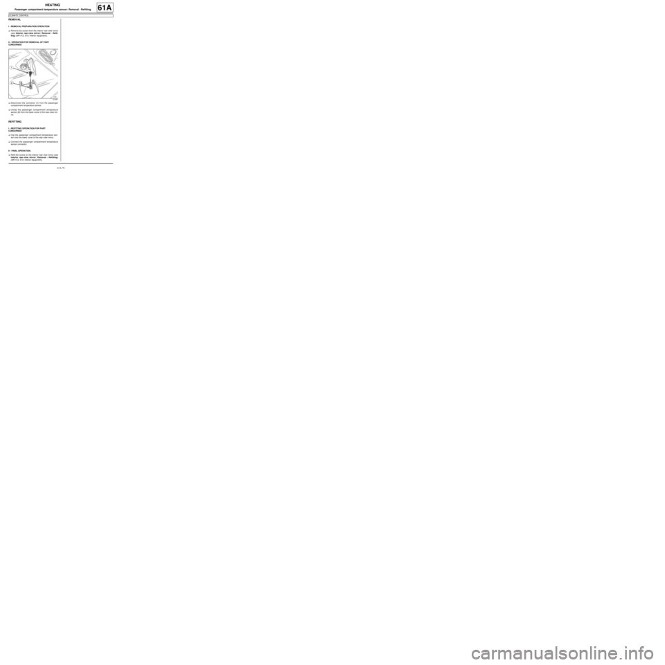
aDisconnect the connector (1) from the passenger
compartment temperature sensor.
aUnclip the passenger compartment temperature
sensor (2) from the lower cover of the rear-view mir-
ror.
REFITTING
I - REFITTING OPERATION FOR PART
CONCERNED
aClip the passenger compartment temperature sen-
sor onto the lower cover of the rear-view mirror.
aConnect the passenger compartment temperature
sensor connector.
II - FINAL OPERATION.
aRefit the covers on the interior rear-view mirror (see
Interior rear-view mirror: Removal - Refitting)
(MR 412, 57A, Interior equipment).
121467
Page 84 of 122
62A-3
AIR CONDITIONING
Air conditioning: List and location of components
AIR CONDITIONING or CLIMATE CONTROL
62A
121397
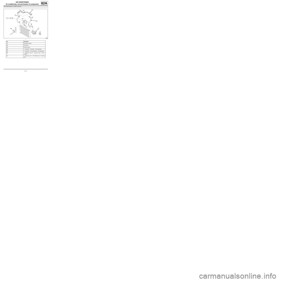
No. Description
(1)Dehydrator reservoir
2()Compressor
(3)Pressure sensor
(4) « Compressor - condenser » connecting pipe
(5) « Compressor - intermediate pipe » connecting pipe
(6) « Dehydrator reservoir - expansion valve » connect-
ing pipe
(7) « Expansion valve - intermediate pipe » connecting
pipe
Page 85 of 122
62A-4
AIR CONDITIONING
Air conditioning: Check
AIR CONDITIONING or CLIMATE CONTROL
62A
I - PREPARATION OPERATION FOR THE
MEASUREMENT DEVICE
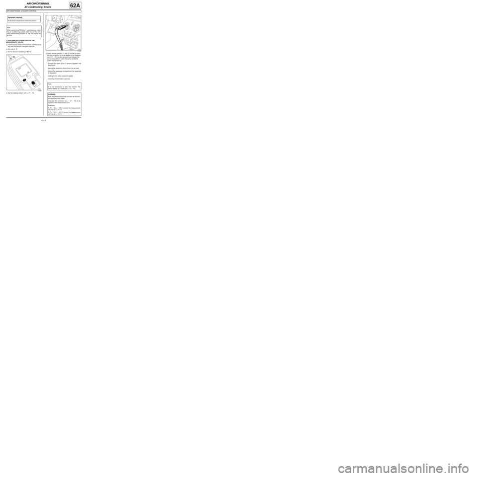
aCheck that the measurement device functions prop-
erly (see the device's instruction manual).
aSet units to ˚C.
aSet the device's sensitivity to 0.1˚C.
aSet the reading mode to (∆T) = (T1 - T2)aCheck the two sensors T1 and T2 in order to calcu-
late the correction (∆) to be applied to the measure-
ment (T1 - T2). the two sensors must indicate the
same measurement under the same conditions.
Check the sensors by:
-bringing the ends of the 2 sensors together until
they touch,
-placing the sensors in the air flow of an air vent,
-setting the passenger compartment fan assembly
to top speed.
-waiting for the value to become stable.
-recording the correction value (∆). Equipment required
Dual-sensor temperature measuring device
Note:
When performing RENAULT maintenance, check
the air conditioning system at the end of the vehi-
cle's maintenance program so that the engine will
be cold.
119360
119358
Note:
It is not necessary to start the vehicle. The
device display is in mode (∆T) = (T1 - T2).
WARNING
Note the diff erence and sign as soon as the tem-
per ature becomes stable.
Calculate the correction (∆) = - (T1 - T2) to be
applied to the measurement (∆T).
Examples:
If (T1 - T2) = - 0.3˚C, correct the measurement
(∆T) by (∆) = + 0.3˚C
If (T1 - T2) = + 0.3˚C, correct the measurement
(∆T) by (∆) = - 0.3˚C
Page 86 of 122
62A-5
AIR CONDITIONING
Air conditioning: Check
AIR CONDITIONING or CLIMATE CONTROL
62A
II - VEHICLE PREPARATION OPERATION
aPut the vehicle in the shade, where the temperature
is greater than or equal to 15˚C minimum.
aClose the bonnet.
aOpen the front windows.
aStart the engine and let it idle.
aSet the air conditioning controls with:
-recirculation mode in the external position,
-the ventilation distribution in "face" mode,
-the temperature control to coldest temperature set-
ting in front (and at the back, if it exists),
-the speed of the passenger compartment fan as-
sembly set to maximum (switch off the rear control
if it exists),
-the front side and centre air vents open with the
vanes in a neutral position,
-the air conditioning system must be turned on (indi-
cator light illuminated).
aWait 5 minutes with the engine idling before tak-
ing any measurements.
III - MEASUREMENTS
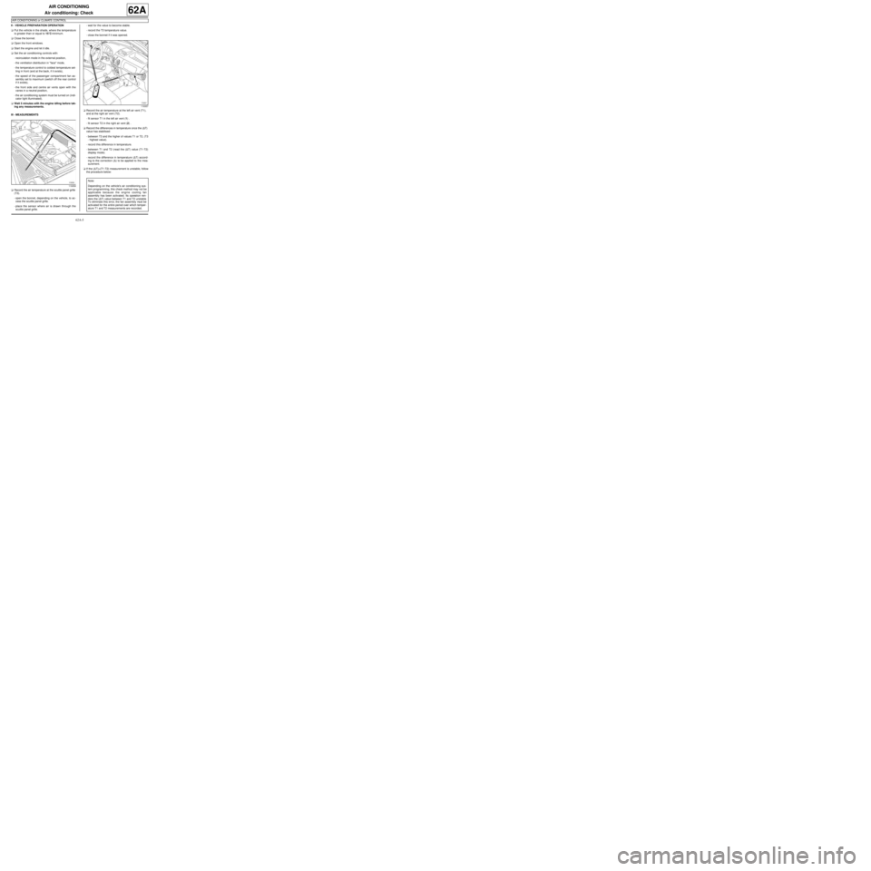
aRecord the air temperature at the scuttle panel grille
(T3).
-open the bonnet, depending on the vehicle, to ac-
cess the scuttle panel grille.
-place the sensor where air is drawn through the
scuttle panel grille.-wait for the value to become stable.
-record the T3 temperature value.
-close the bonnet if it was opened.
aRecord the air temperature at the left air vent (T1),
and at the right air vent (T2).
-fit sensor T1 in the left air vent (1) .
-fit sensor T2 in the right air vent (2) .
aRecord the differences in temperature once the (∆T)
value has stabilised:
-between T3 and the higher of values T1 or T2, (T3
- highest value).
-record this difference in temperature.
-between T1 and T2 (read the (∆T) value (T1-T2)
display mode).
-record the difference in temperature (∆T) accord-
ing to the correction (∆) to be applied to the mea-
surement.
aIf the (∆T)=(T1-T2) measurement is unstable, follow
the procedure below:
119359
119357
Note:
Depending on the vehicle's air conditioning sys-
tem programming, this check method may not be
applicable because the engine cooling fan
assembly has been activated. Its operation ren-
ders the (∆Τ) value between T1 and T2 unstable.
To eliminate this error, the fan assembly must be
activated for the entire period over which temper-
ature T1 and T2 measurements are recorded.
Page 102 of 122
62A-21
AIR CONDITIONING
Expansion valve: Removal - Refitting
AIR CONDITIONING or CLIMATE CONTROL
62A
REMOVAL
I - REMOVAL PREPARATION OPERATION
a
aDrain the refrigerant circuit using a refrigerant
charging station (see 62A, Air conditioning, Re-
frigerant circuit: Draining - Filling, page 62A-8) .
aDisconnect the battery (see ) (80A, Battery).
aRemove:
-the wiper arms (see Windscreen wiper arm: Re-
moval - Refitting) (85A, Wiping - Washing),
-the scuttle panel grille (see Scuttle panel grille:
Removal - Refitting) (56A, Exterior equipment),
-the scoop under the scuttle panel grille (see Scoop
under the scuttle panel grille: Removal - Refit-
ting) (56A, Exterior equipment).
aRemove:
-the air filter unit (see Air filter unit: Removal - Re-
fitting) (12A, Fuel mixture),
-the upstream oxygen sensor (see Oxygen sen-
sors: Removal - Refitting) (17B, Petrol injection). Equipment requiredrefrigerant charging station
compressed air nozzle
IMPORTANT
To avoid all risk of damage to the systems, apply
the safety and cleanliness instructions and opera-
tion recommendations before carrying out any
repair:
- (see 62A, Air conditioning, Air conditioning:
Precautions for the repair, page 62A-1) ,
- (see Vehicle: Precautions for the repair) (01D,
Mechanical introduction).
Note:
Use blanking plugs for the fuel circuits with part
numbers 77 01 208 229 or 77 01 476 857 to plug
any openings exposed to the open air. They must
be clean. Do not use any which have already been
used to plug a fuel circuit.
WARNING
To prevent moisture from entering the system,
place plugs on the cold loop components which are
open to the air.
WARNING
In order to avoid any refrigerant leaks, do not dam-
age (deform, twist, etc.) the pipe.
WARNING
To prevent the surrounding components from over-
heating, do not damage (tear, pierce, bend, etc.) a
heat shield.
Any damaged heat shields must be replaced.WARNING
Consult the device's operating manual to avoid
incorrect use.
D4F, and 780 – K4M, and 854
Page 104 of 122
62A-23
AIR CONDITIONING
Expansion valve: Removal - Refitting
AIR CONDITIONING or CLIMATE CONTROL
62A
REFITTING
I - REFITTING PREPARATION OPERATION
a
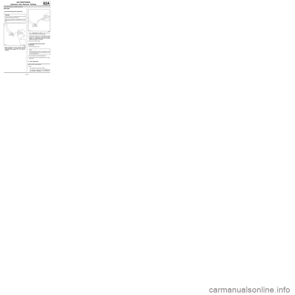
aClean the surface and seal of the pipe using EN-
GINE CLEANER (see Vehicle: Parts and con-
sumables for the repair) (04B, Consumables -
Products).aUse a compressed air nozzle to blow on the sur-
face and the seal of the connecting pipe.
aLubricate the surface of the connecting pipe and the
seal with air conditioning oil (see 62A, Air condi-
tioning, Air conditioning: Parts and consum-
ables for the repair, page 62A-2) .
aRemove the blanking plugs.
II - REFITTING OPERATION FOR PART
CONCERNED
aRefit the expansion valve.
aFit the expansion valve connecting pipes.
aRefit the bolts of the connecting pipes on the expan-
sion valve.
III - FINAL OPERATION
aRefit:
-the bulkhead heat-resistant protectors,
-the upstream oxygen sensor (see Oxygen sen-
sors: Removal - Refitting) (17B, Petrol injection), WARNING
Do not remove the blanking plugs from each
component until the last moment.
Also, do not remove the components from their
packaging until they are to be fitted to the vehi-
cle.
143880
143882
Note:
Gradually tighten the bolts of the expansion valve
so that the expansion valve is positioned evenly
on the distr ibution unit.
D4F, and 780 – K4M, and 854
Page 110 of 122
62A-29
AIR CONDITIONING
Dehydrator reservoir - expansion valve connecting pipe: Removal - Refitting
AIR CONDITIONING or CLIMATE CONTROL
62A
II - OPERATION FOR REMOVAL OF PART
CONCERNED
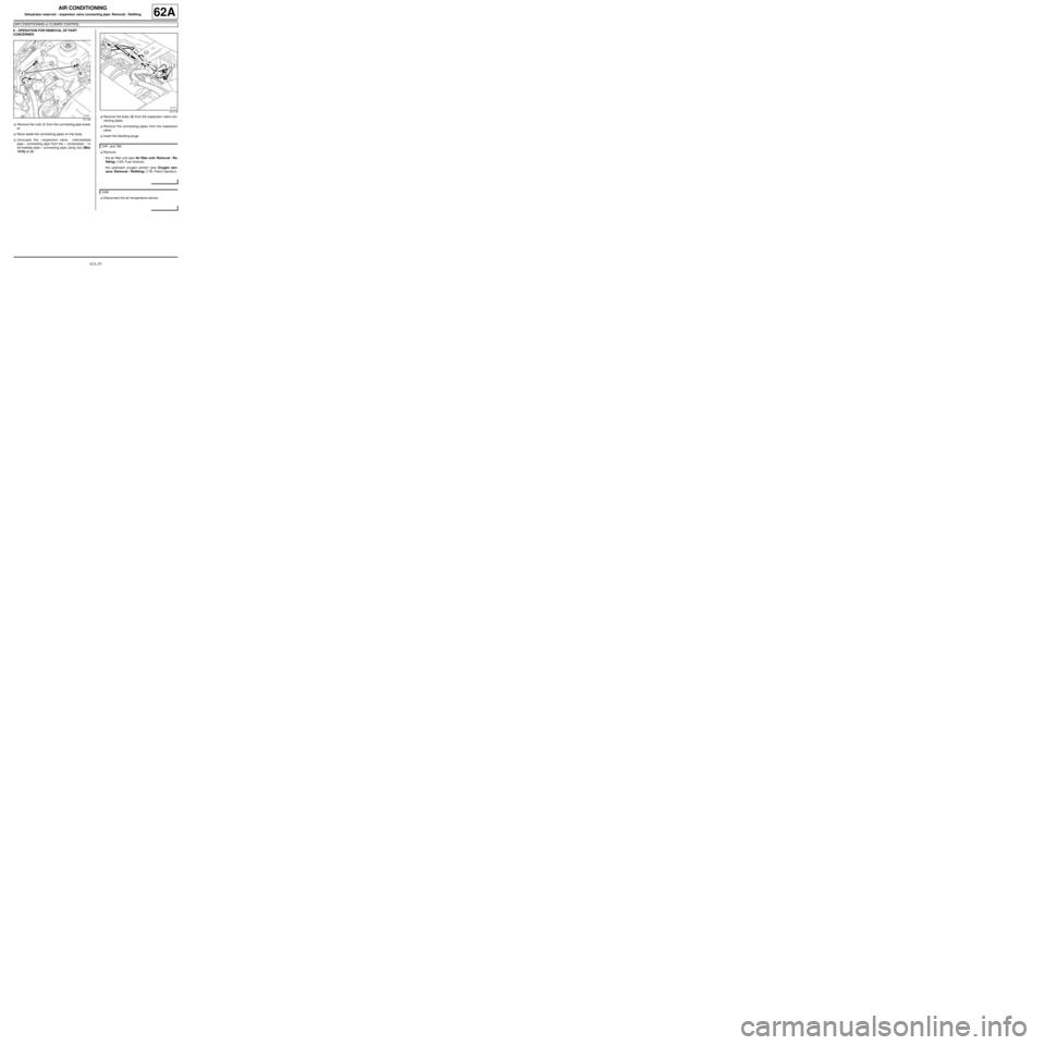
aRemove the nuts (1) from the connecting pipe brack-
et.
aMove aside the connecting pipes on the body.
aUncouple the « expansion valve - intermediate
pipe » connecting pipe from the « compressor - in-
termediate pipe » connecting pipe using tool (Mot.
1410) at (2) .aRemove the bolts (3) from the expansion valve con-
necting pipes.
aRemove the connecting pipes from the expansion
valve.
aInsert the blanking plugs.
aRemove:
-the air filter unit (see Air filter unit: Removal - Re-
fitting) (12A, Fuel mixture),
-the upstream oxygen sensor (see Oxygen sen-
sors: Removal - Refitting) (17B, Petrol injection).
aDisconnect the air temperature sensor.
121180
121178
D4F, and 780
K4M
Page 112 of 122
62A-31
AIR CONDITIONING
Dehydrator reservoir - expansion valve connecting pipe: Removal - Refitting
AIR CONDITIONING or CLIMATE CONTROL
62A
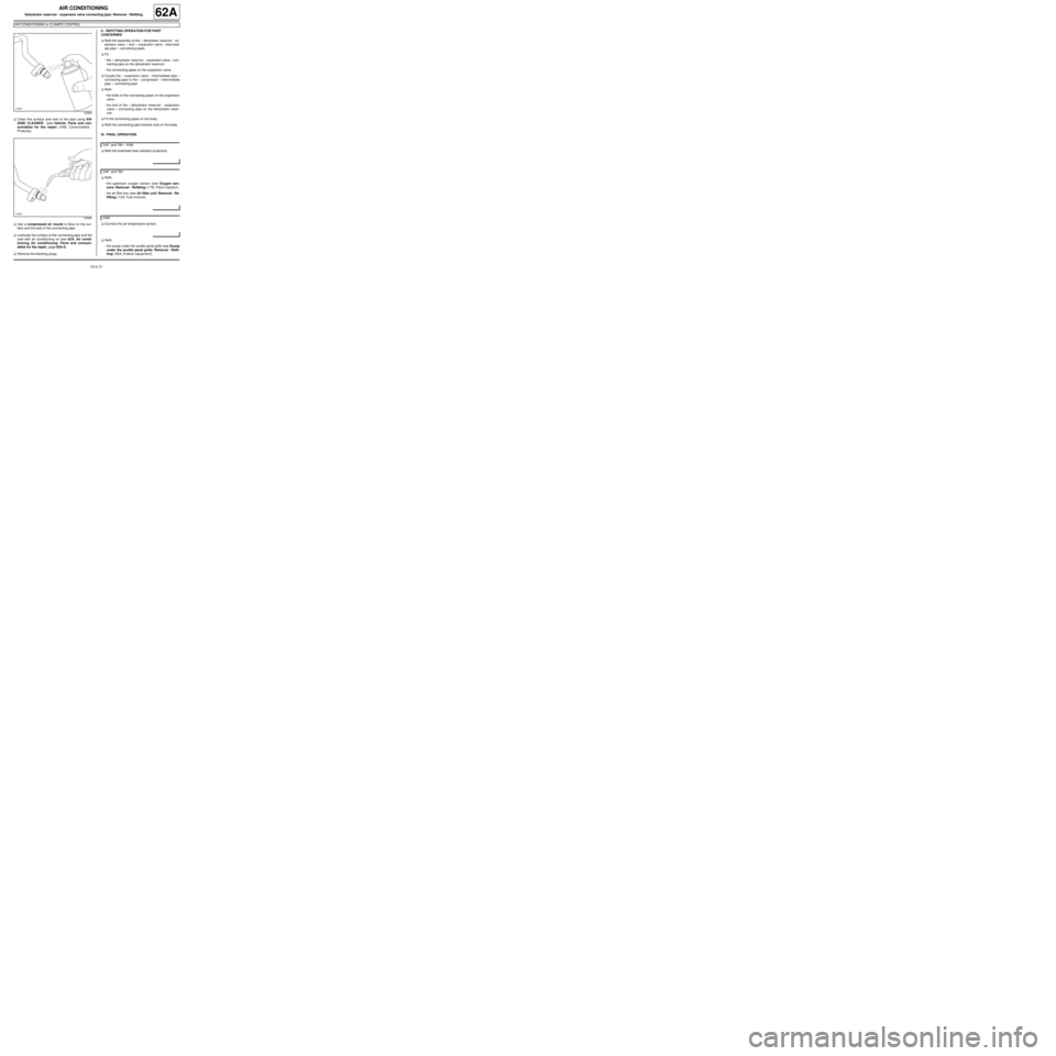
aClean the surface and seal of the pipe using EN-
GINE CLEANER (see Vehicle: Parts and con-
sumables for the repair) (04B, Consumables -
Products).
aUse a compressed air nozzle to blow on the sur-
face and the seal of the connecting pipe.
aLubricate the surface of the connecting pipe and the
seal with air conditioning oil (see 62A, Air condi-
tioning, Air conditioning: Parts and consum-
ables for the repair, page 62A-2) .
aRemove the blanking plugs.II - REFITTING OPERATION FOR PART
CONCERNED
aRefit the assembly of the « dehydrator reservoir - ex-
pansion valve » and « expansion valve - intermedi-
ate pipe » connecting pipes.
aFit:
-the « dehydrator reservoir - expansion valve » con-
necting pipe on the dehydrator reservoir,
-the connecting pipes on the expansion valve.
aCouple the « expansion valve - intermediate pipe »
connecting pipe to the « compressor - intermediate
pipe » connecting pipe.
aRefit:
-the bolts of the connecting pipes on the expansion
valve,
-the bolt of the « dehydrator reservoir - expansion
valve » connecting pipe on the dehydrator reser-
voir.
aFit the connecting pipes on the body.
aRefit the connecting pipe bracket nuts on the body.
III - FINAL OPERATION
aRefit the bulkhead heat-resistant protectors.
aRefit:
-the upstream oxygen sensor (see Oxygen sen-
sors: Removal - Refitting) (17B, Petrol injection),
-the air filter box (see Air filter unit: Removal - Re-
fitting) (12A, Fuel mixture).
aConnect the air temperature sensor.
aRefit:
-the scoop under the scuttle panel grille (see Scoop
under the scuttle panel grille: Removal - Refit-
ting) (56A, Exterior equipment),
143880
143882
D4F, and 780 – K4M
D4F, and 780
K4M